
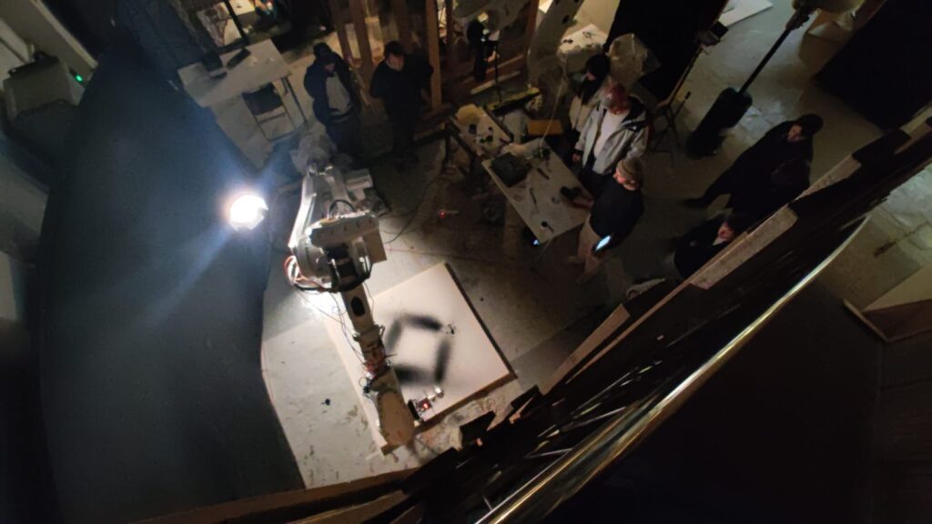
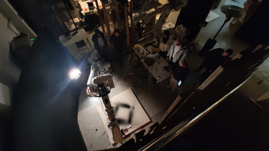
For our second studio task the aim was to further experiment painting with robots; this time extending what paintings could be achieved when a standard brush was replaced by a custom made ‘spilling’ end effector controlled by an Arduino Uno.
This was set through the brief as:
To explore and consider, how a tool might interact with a robot and what movements can be enhanced through robotic intervention. It should also reflect on the unique opportunities and possible limitations that arise when working with robotic arms at this scale.
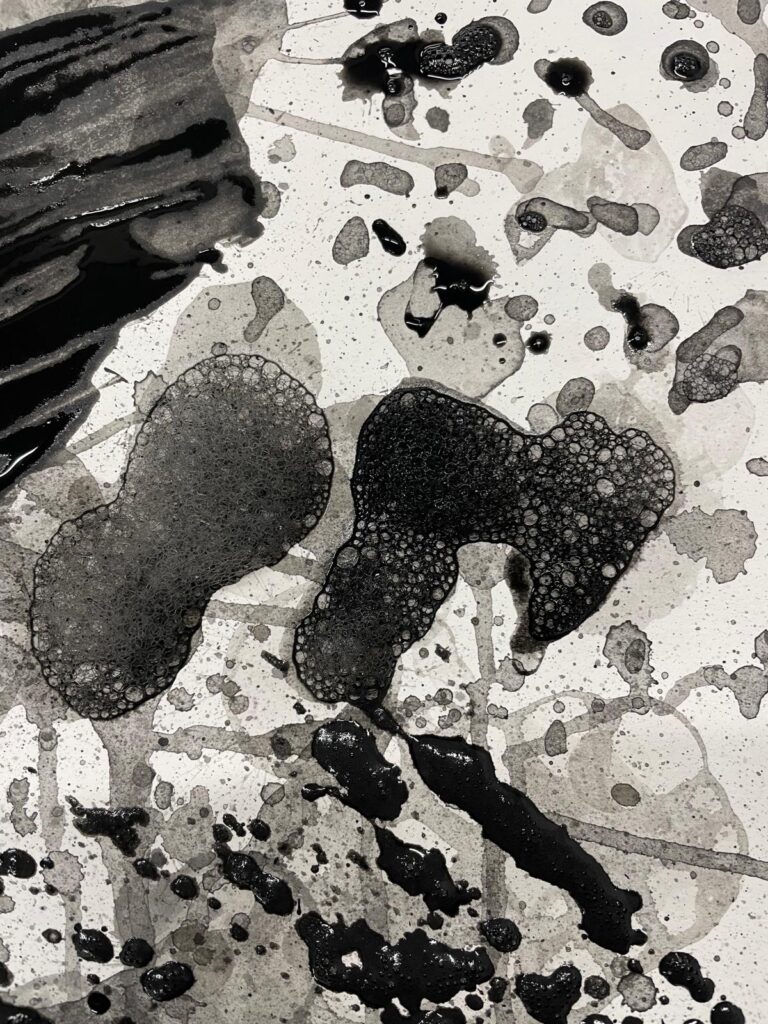
Conceptually, we also wished to challenge the material we were using. Not just asking what the anatomy of the robot was but extending this as question of thinking to the paint material itself. Initially we tried to achieve this mean via mixes. At first this meant mixing soap water and air with the paint to create different bubble patterns.
Although this produced very interesting outcomes, this also began a follow up conversation about precision and control. We thought about how with just air and paint we could also ‘spill’ the material.
Initial Explorations
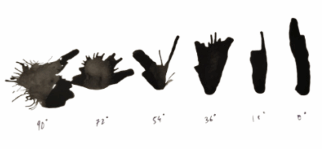
With just air and paint we could begin to play with a grid and angular changes which reflect a great advantage of using the robot over a person producing the art. Here you can see the difference between angular steps and number of air pumps applied.
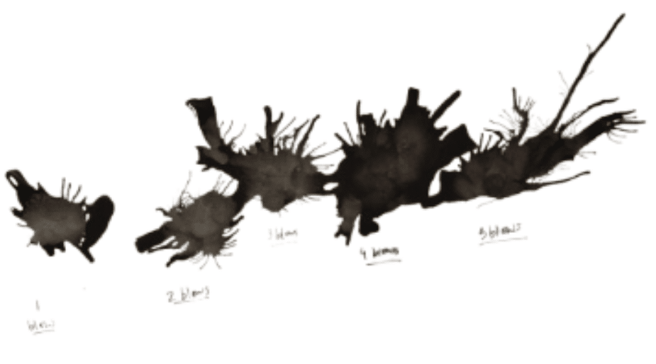
Concept at manual stage
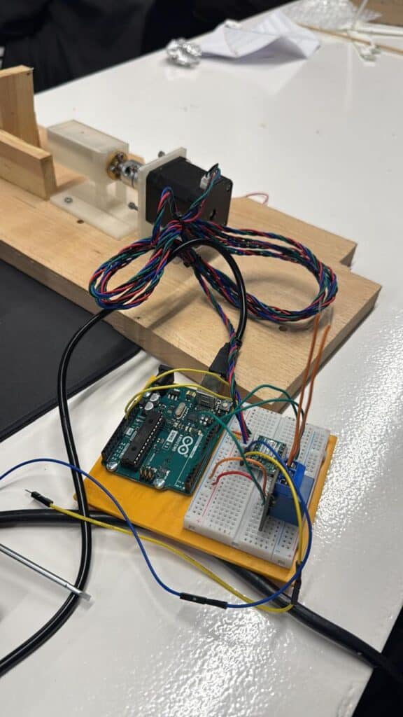
Although we now had a concept, we had to transform the manual into the electronic using an Arduino set up to produce the same outcomes. As a breakdown these are three of the design issues we faced with with producing the final outcome, although the actual process involved a lot more tinkering!
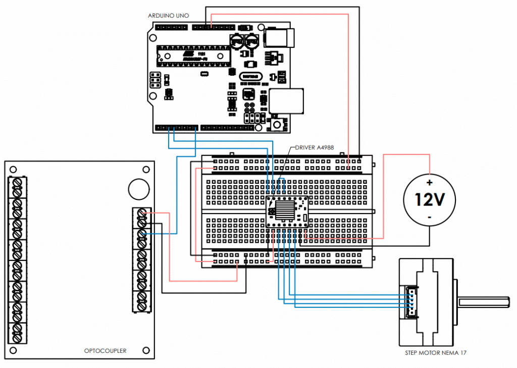
- Initially we tried a 28BY-J stepper motor with a ULN2003 driver. This worked but did not provide enough power to squeeze the paint
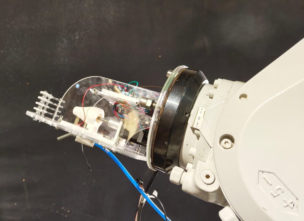
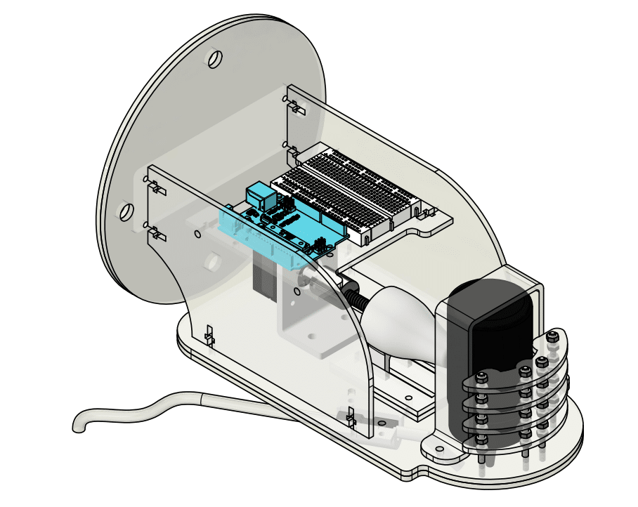
- We then moved up to a NEMA-17 Stepper with an A498 driver (with attached heat sink). We noticed that squeezing with our fingers still produced a much more controlled spilling pattern. As a result the flat squeezing tool shown on the left was changed out for a convex pusher and wall as shown on the right.
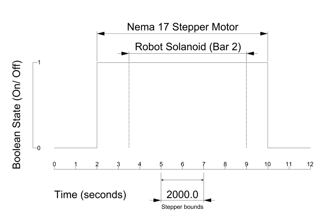
- Syncing the Arduino with the air. In our final trial we realised that even being a tiny step out between the Arduino stepper bounds and solanoid timing meant that over the course of the robot’s movements would no longer work together. Our final challenge was timing the stepper bounds with a delay so that the solanoid would precisely turn on and off before and after the squeezing to ensure we were spilling the paint each time.
Prototyping to Final
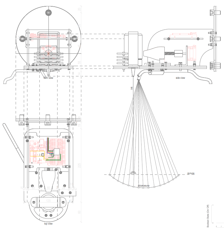
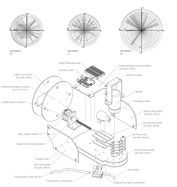
Final drawings
The final path followed a grid logic where the robot changed along a 0 degree to 45 degree rotation along the Y axis and a height change along the X- axis. The canvas made of a 1500mm x 1500mm linen surface was rotated manually to change the height variation along the X-axis hence you can you see the greater spray along the different rotations.
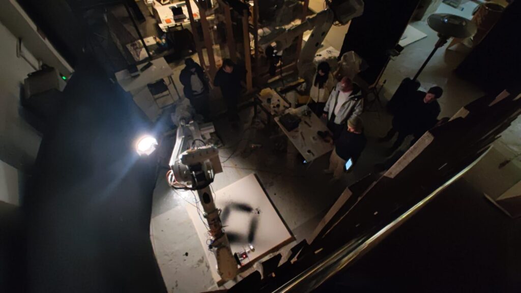
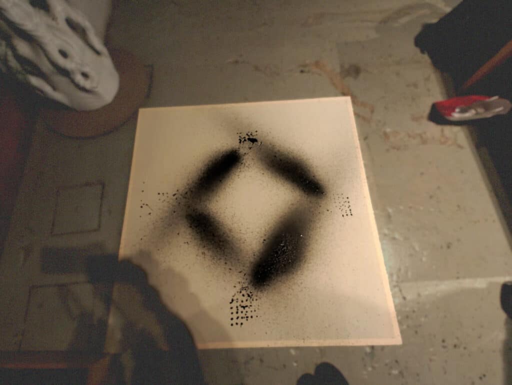
Final Painting
