Our concept
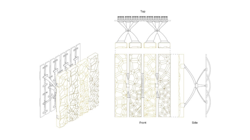
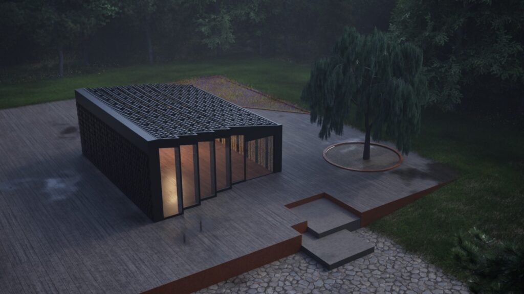
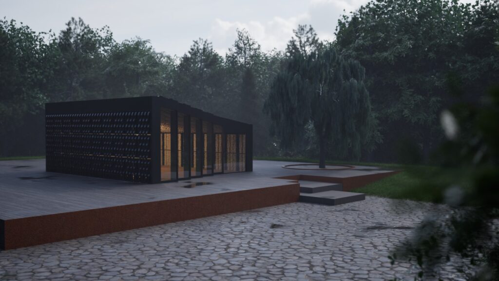
Kit of Parts is inspired by homes that can be easily assembled and disassembled and adapt in size. We are living in an ever changing world that is under a lot of stress caused by climate change. We thought that a cabin that could move easily and become smaller or larger was a potential solution in moments of environmental emergency.
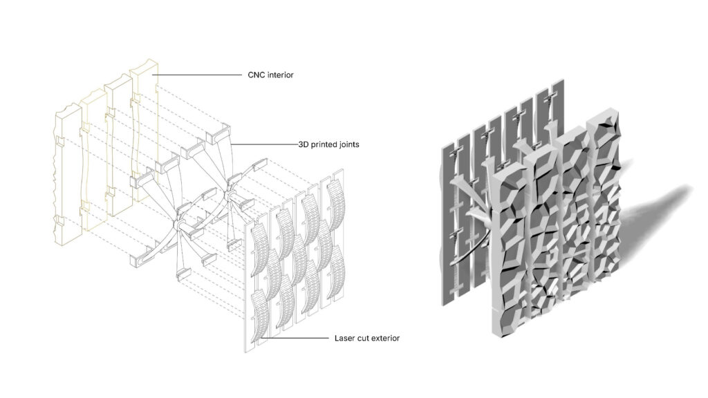
In terms of the assignment, we were interested in creating a kit of parts that could be easily replicated in a real life scenario. We wanted a system that was efficient to build, scalable and that didn’t require glue. We decided to design a facade system that incorporates all three technologies in a smart and seamless way.
Laser cutting
References
Our Design
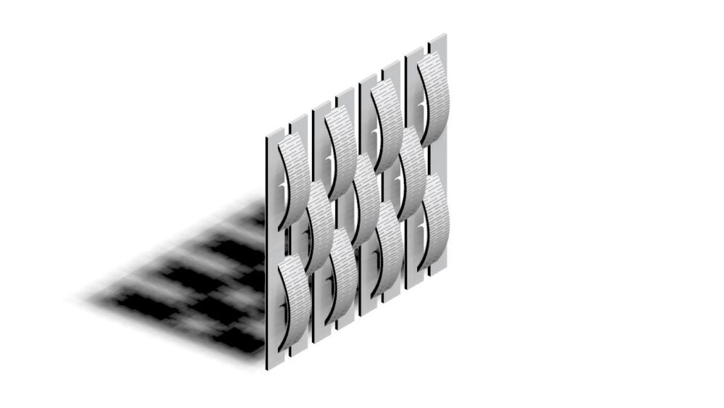
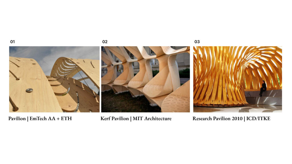
We are inspired by the bending technique shown with other timber structures, but in order to achieve this without the use of steam bending, we formulated another way to approach this. We decided to go for a design that combined curved and straight elements through interlocking. We were also interested in our facade having some porosity to allow air flow as well as interesting shadows.
Technical Drawings
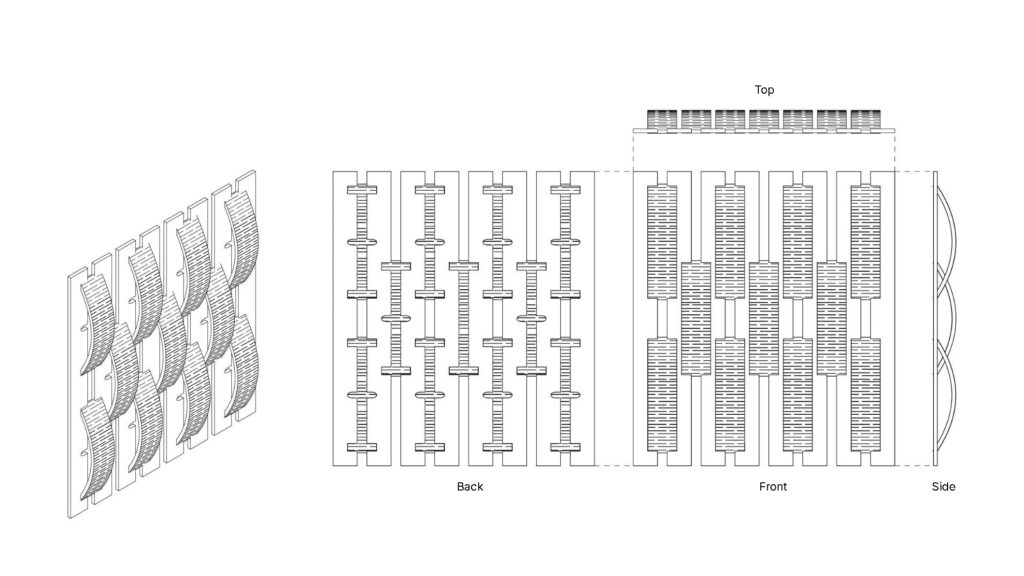
For the production of the final geometry, we worked with 4mm plywood. We used a total of 441 x 383 mm of material to complete it. The time to cut the design was 33 minutes. The production file includes red as well as blue lines for the laser to differentiate between interior and exterior cuts. The cutting parameters were 42.00 power and 1.80 speed for both. We made the interlocking tolerances twice as wide as the material thickness to allow for the material to bend at a specific curvature.
Prototyping & Fabrication
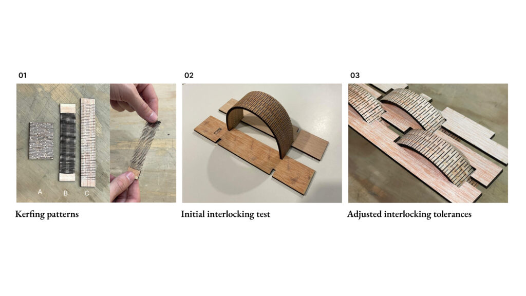
We tested various kerfing patterns to find one that could bend without breaking. Pattern A allowed multidirectional bending, but intersecting lines created weak points. Pattern B was very flexible due to zigzag cuts, but it was overly pliable for our needs. Pattern C struck a balance, bending well without creating weak spots or losing shape. Adjusting the cutting width improved bendability, though it reduced structural rigidity. Our final design featured single-line cuts at the endpoints for strength, with a slightly wider cut in the middle to enhance connection tolerance and maintain an optimal form. After testing different widths for the best interlocking tolerance, we found that an 8mm width paired best with our desired bend in the kerfing elements, optimizing structural rigidity.
Final Geometry
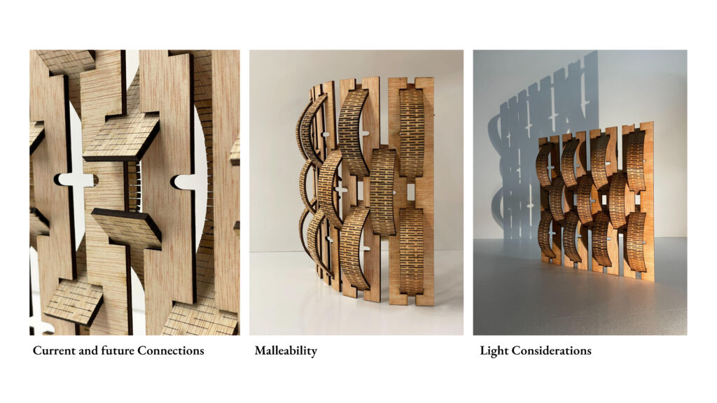
We have incorporated biscuit joints within our laser cut facade in order to refine the connection between technological fabrications. Our interlocking system allows for flexible and adaptable design considerations, becoming sturdy when paired to our 3D- printed structural elements. Having a Porous facade allows for ample light to penetrate into the cabin to create unique shadows dependent on time of day.
3D printing
References

Our Design
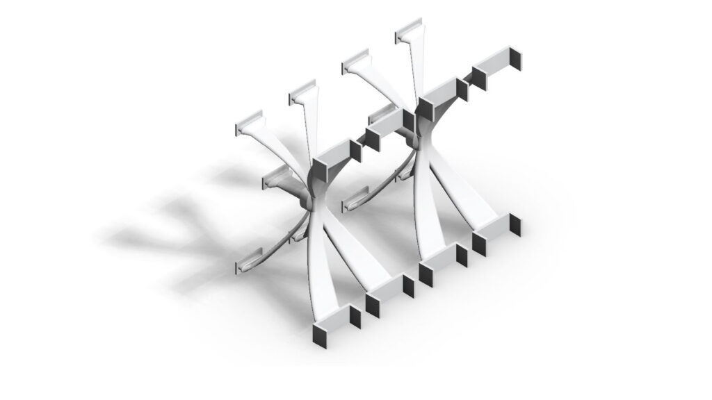
When thinking about the 3D printed portion for our cabin, we didn’t want it to be completely isolated element from the laser cut and CNC pieces. We wanted to create a joinery system using 3D printing because, through its additive nature, it allows for more complex and curved shapes compared to the other technologies. We decided to design a piece with legs that could extend to different directions from a strong middle point in order to allow connections to the laser cut and CNC elements on opposite sides. It was really important for us to minimize the amount of supports in our prints because we wanted to replicate the real-life scenario of 3D printing our design at 1:1 scale.
Technical Drawings
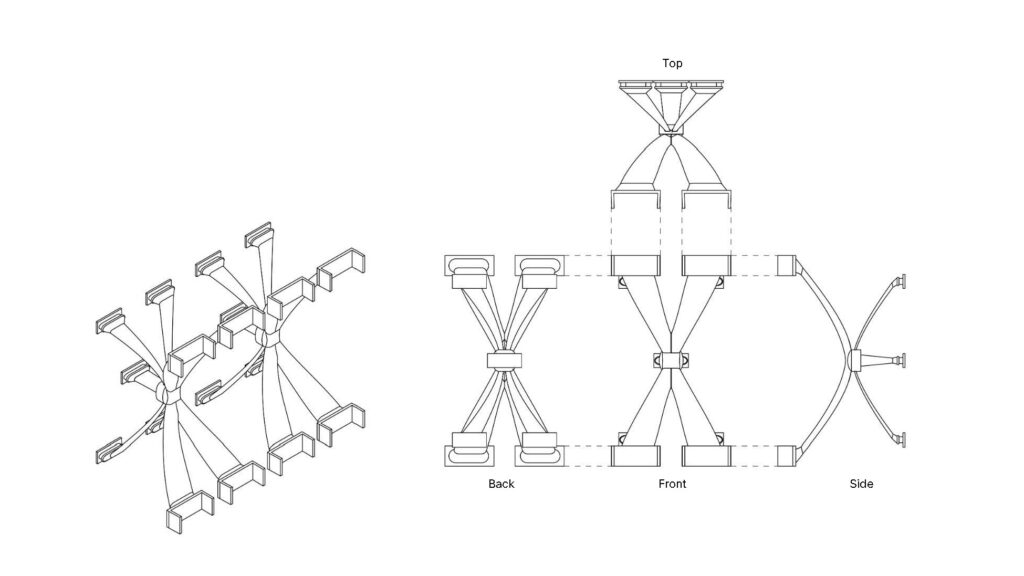

Prototyping & Fabrication
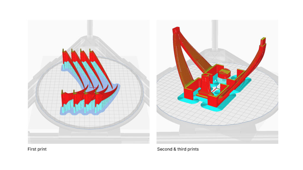
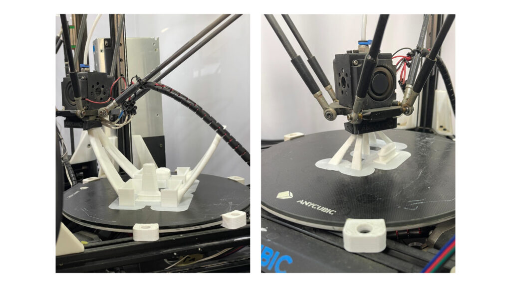
For our final design, we had to run three separate prints in the Anycubic printer. We had many elements that interlock with each other. We placed them in such a way that we had minimal supports, which optimized the printing process.
For all prints: Filament: White PLA, Temperature: 210°C, Layer height & line width: 0.3, Infill percentage: 40%, Walls: 1
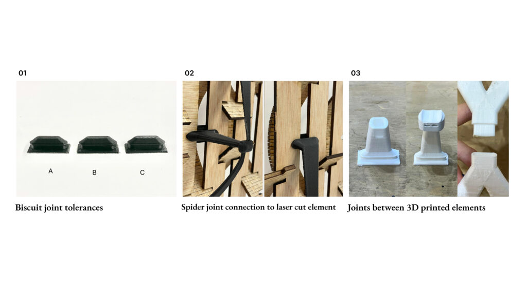
Our first prototyping step was to test tolerances between laser-cut holes and 3D-printed joints. Joint A matched the hole size exactly, Joint B was offset by 0.5 mm, and Joint C by 0.75 mm. After finding the ideal fit for the biscuit joint, we explored connecting them to a central point using curved “legs.” To reduce print time and avoid supports, we decided to print the piece in parts that slot together instead of as a single piece. This led us to test various tolerances and slotting systems to ensure a good fit and stable assembly.
Final Geometry
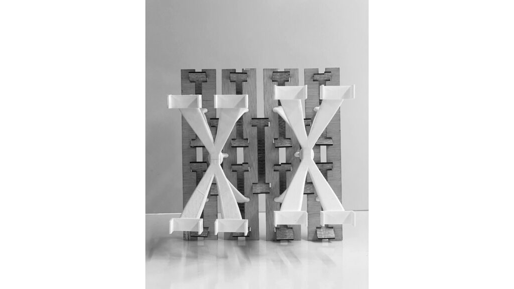
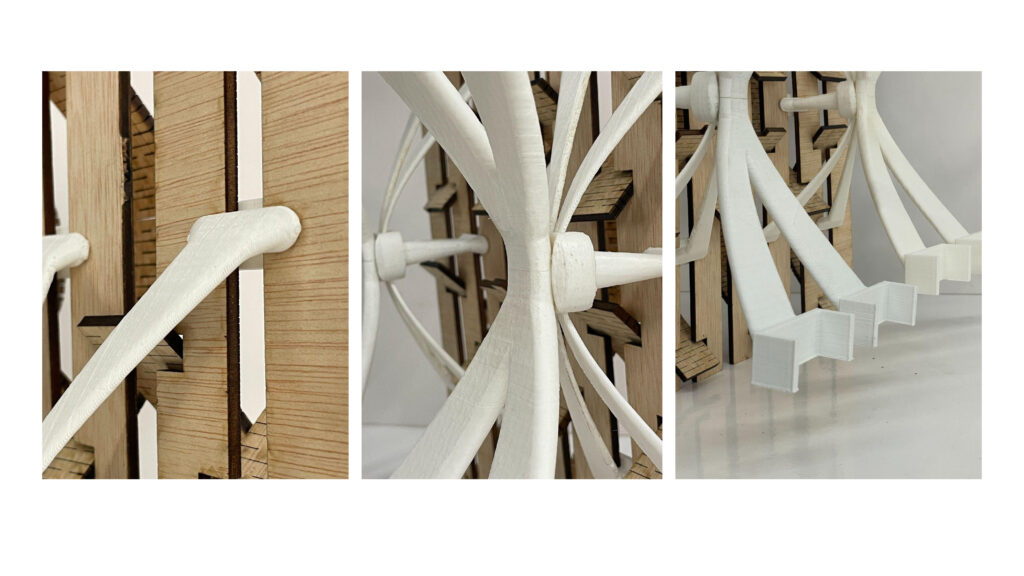
Everything in our design was designed to interlock without the necessity for glue. We opted for a curved design that was possible through additive manufacturing. We couldn’t have achieved the same result otherwise. We have designed clamps that will allow us to attach our CNC design later on.
CNC Milling
References
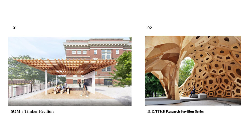
Our design
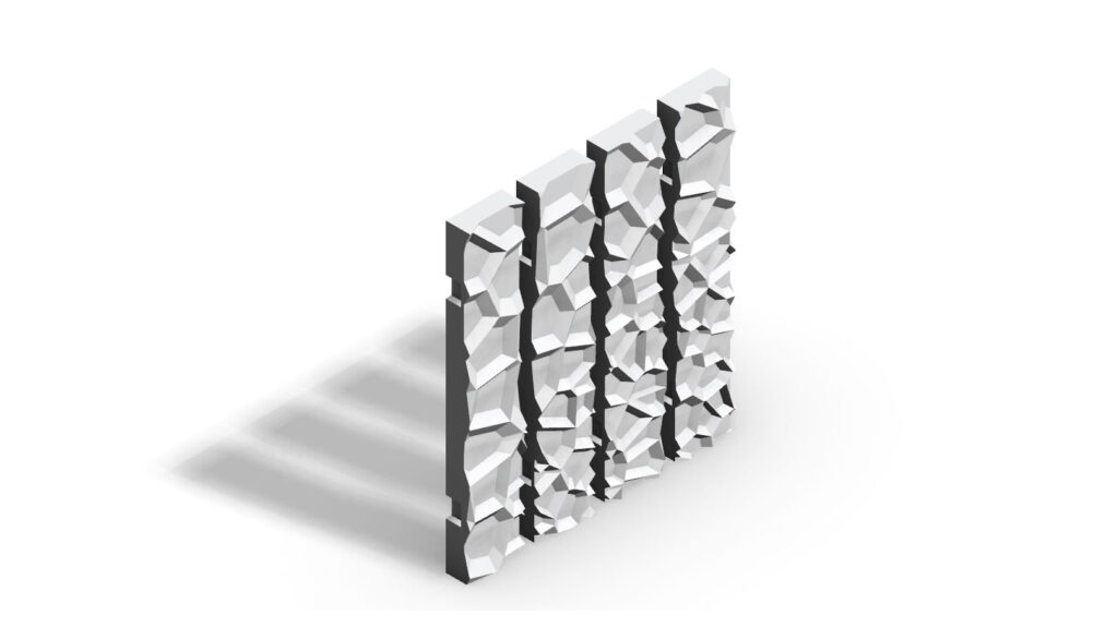
Our CNC approach focuses on creating a visually seamless facade by integrating CNC milled and 3D-printed components in a way that hides the joints. The goal is to allow these parts to connect smoothly, without visible interruptions, so that the facade maintains a clean, cohesive look. This concept combines precise milling and innovative joining techniques, achieving both structural integrity and aesthetic flow. By concealing the joints, we emphasize the elegance of the overall design, enhancing both its functionality and visual appeal.
Technical Drawings
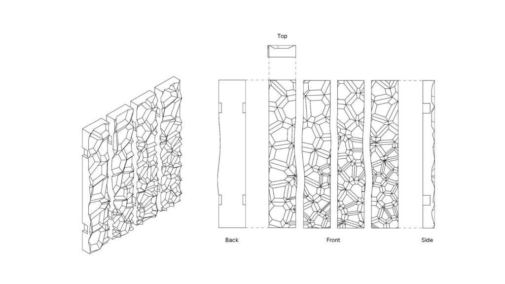
Prototyping & Fabrication
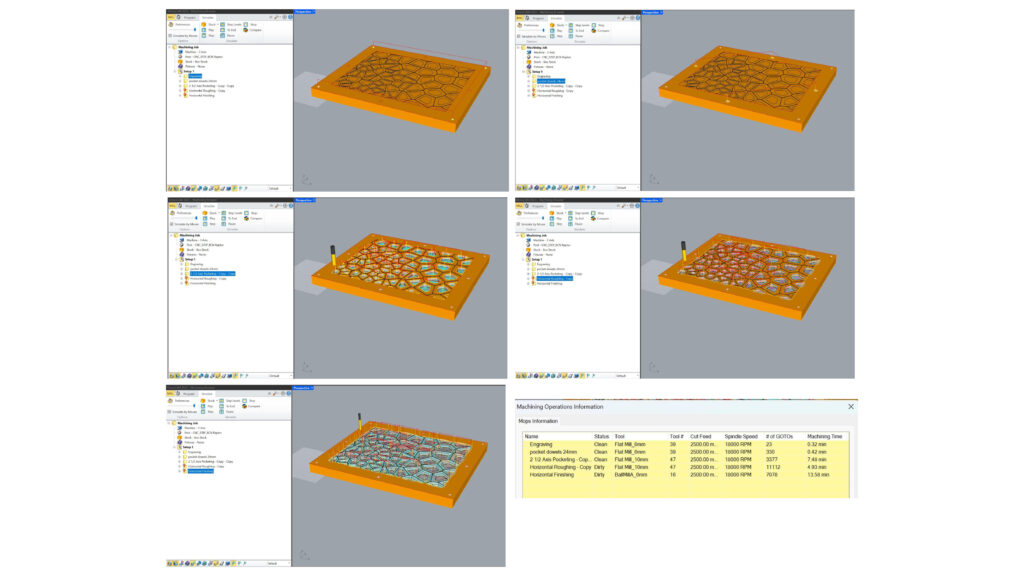
Front side machine operations:
- Engraving for screws with a Flat 6 mm and took 0.32 mins
- Pocketing for dowels with a Flat 6 mm and took 0.42 mins
- 2 ½ Axis Pocketing with a Flat 10 mm and took 7.48 mins
- Horizontal Roughing with a Flat 10 mm and took 4.93 mins
- Horizontal Finishing with a Ball 6 mm and took 13.58 mins
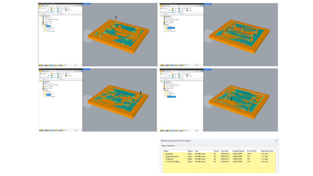
Back side machine operations:
- Pocketing with a Flat 6 mm and took 3.61 mins
- Engraving for screws with a Flat 6 mm and took 1.37 mins
- Engraving for corner points with a Flat 6 mm and took 3.12 mins
- 2 ½ Axis Pocketing with a Flat 6 mm and took 3.61 mins
All operations were done at a 2500 cut feed and 18000 RPM spindle speed.
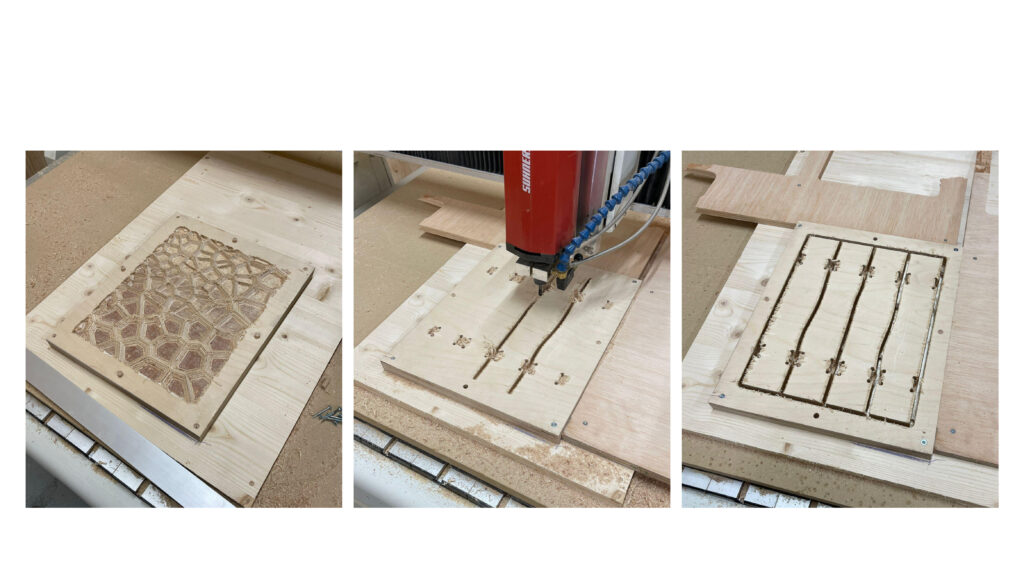
We started by creating holes for screws and dowels to secure the material, then we milled the voronoi design, and when done, we flipped the plywood using the dowels as positioning guides and milled the backside into four separate pieces with slots for inserting into the 3D printed joints.
Assembled System
