
Hypothesis
Abstract
Seen by some as a novel construction technique, earth 3D printing is a promising digital fabrication method trying to eliminate the transport of building materials as much as possible. The main biomaterial lies just beneath our feet: earth. Although large creative freedom comes with digital fabrication, many challenges that are specific to 3D printing still need plenty of research and experimentation to advance this upcoming field.
One of these difficulties is dealing with the high risk of failure (compared to traditional construction methods like brick-laying). Especially when tackling the closing of spaces and the roof. The behaviour of a wet print is unpredictable and stability is what needs to be achieved.
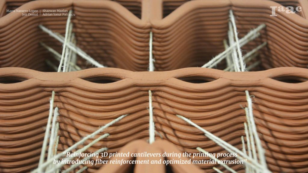
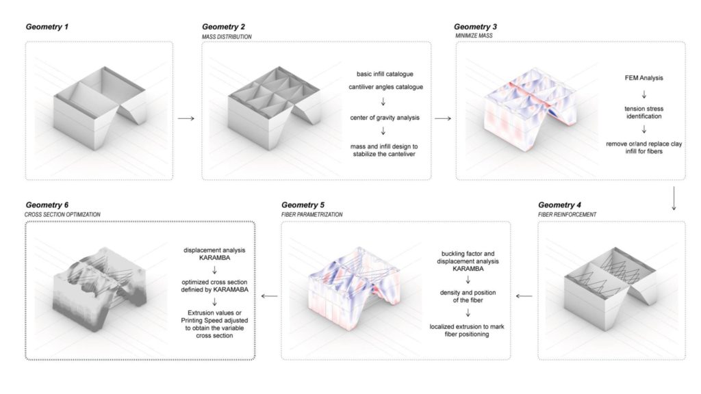
This research looks into the possibility of integrating and combining two reinforcement strategies during printing. First, the introduction of continuous fibres as ties between cantilevering surfaces and second a structural cross-section optimisation of the models through the variation of the extrusion rate.
Geometrical and fabrication parameters are researched alongside the material properties of various natural fibres. Through architectural drawing, computational analyses, physical computing, data recording and small-scale clay printing these topics are all tested to eventually discuss the future potential of the proposed methods.
Introduction
Digital fabrication is currently breaking out of the research labs and maker spaces and is more and more prominent within the construction industry. As a consequence, additive manufacturing techniques such as concrete 3D Printing are rapidly progressing and are of interest to construction companies.
Although it is already very difficult to break tradition within the sector as it is, many aspects of 3D printing should still be an improvement for it to become a viable construction option. One of these aspects is the high risk of failure during construction. Due to the wet and plastic state the material needs for extrusion, its structural behaviour before consolidation is very difficult to deal with. Especially for earth printing compared to concrete due to the omission of stabilizers in the mixture.
A major hurdle in 3D Printing is the cantilever. Fully closing up a structure is a challenge that pushes the limits of the existing knowledge of earth extrusion and is the broader context for this research.
Research Hypothesis
To tackle this problem, this research is centred around the following topic:
Reinforcing 3D printed cantilevers during the printing process by introducing fibre reinforcement and optimized material extrusion
A topic that brings forth questions such as
- Which fibre system allows to reach steeper cantilever during printing?
- Can we optimize fibre-reinforced infills to achieve a more stable cantilever during printing?
Methodology
The first stages of the work are characterized by rigorous testing to gain a deeper understanding of the fibre and the basic printing capabilities of the tools at hand. After a solid understanding was gathered, a gradual introduction of reinforcement strategies is initiated in the middle stages of the research. Finally, the last two weeks were for validation of the proposed methods and scaling up.
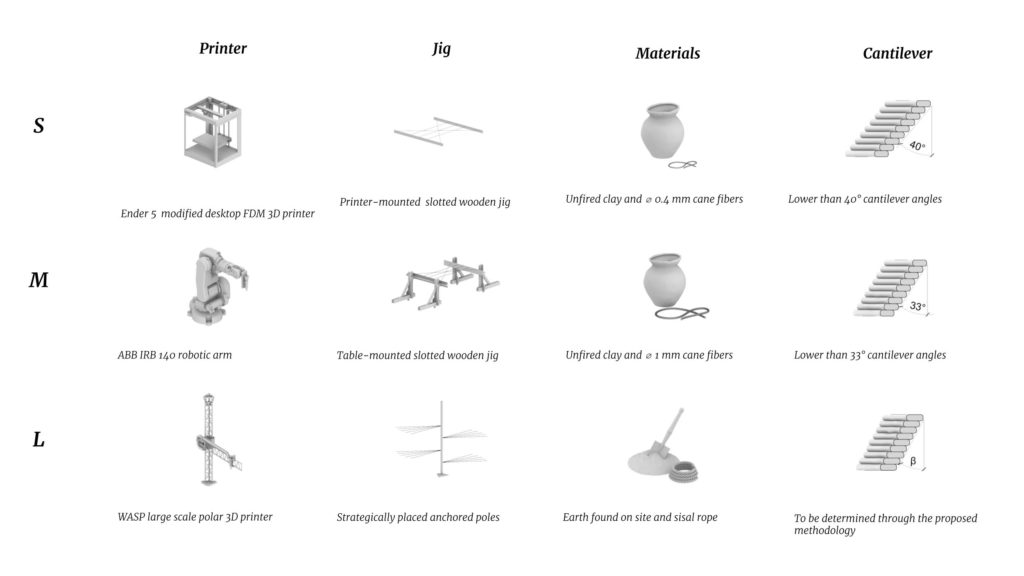
The main research tools used throughout the 7-week duration of the study were:
- Architectural Drawing: plans and sections allow a deeper understanding of the basic geometrical properties and dimensions of each model before printing.
- Digital Analysis: complementing the previous drawings, grasshopper-based workflows allow us to fully model, adapt and tune the three-dimensional properties of each model. Complementary FEM tools (Karamba3D) inform us about the stability and likelihood of a successful print for any given geometry and are key in the final optimisation processes. Evolutionary solvers, such as Galapagos and Wallacei create thousands of different models during the optimisation process, looking for the best performance of the defined goals.
- Fabrication / Printing: Using an Ender 5 3D printer, adapted for clay extrusion with compressed air and an Auger screw setup, most of the prints are fabricated. These prints are regarded as 1:10 scale of reality. A final 1:5 scale print was done with an ABB IRB 140 robotic arm. Printing material was kept constant, a classic red earthenware clay (PF from Sio-2).
- Physical computing: Arduino Uno boards and various sensors were used to log climatic data during the drying of models.
- Photogrammetry and point clouds: using photogrammetry scans and point cloud comparing, detailed shrinkage behaviour can be observed. (Many scans and point clouds were made during the research, but unfortunately, most were left unused due to the learning curve of working with them within the short timeframe of the research.)
- Documentation: picture and video are of critical importance when understanding the behaviour of wet clay. Countless pictures, time-lapses and videos are needed for a proper understanding of earthen 3D Printing.
State-of-the-art
Fifth façade
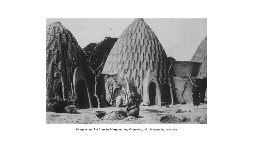
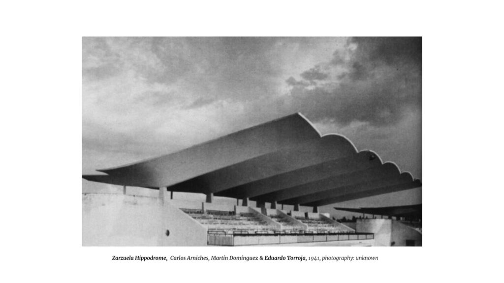
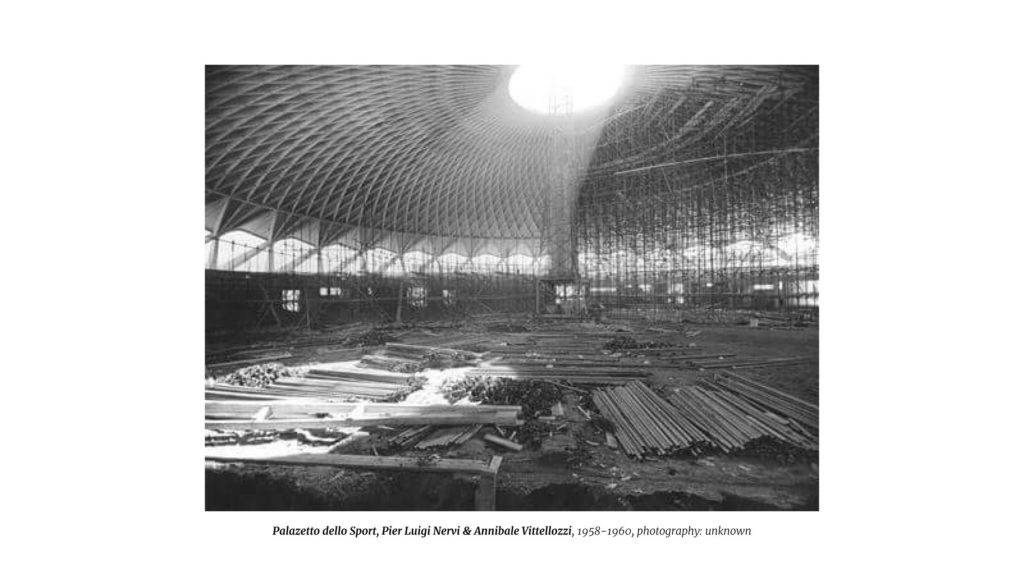
Within the main topic of the research studio Fifth Façade, inspiration can be drawn from historical references. From the vernacular, such as the traditional earthen architecture from the Musgum Tribe in Cameroon to the innovative construction methods developed during the 20th century by the likes of Antoni Gaudi, Edouardo Torroja, Heinz Isler & Pier-Luigi Nervi (to only name a few). Plenty of groundbreaking and beautiful precedents pave the path towards 3D printing an earthen fifth façade.
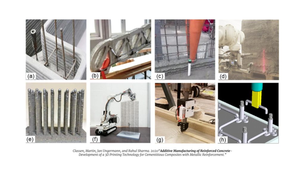
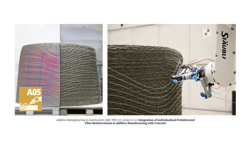
Reinforcements in constructive 3D Printing
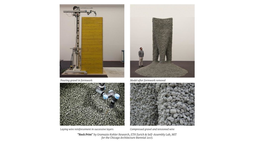
Looking for reinforcement methods in 3D printing, on a constructive scale, quickly leads to articles in concrete reinforcements. (Bos et al. 2017; Classen, Ungermann, and Sharma 2020; Wu, Memari, and Duarte 2022; Gantner et al. 2022; ‘Project A 05 – Additive Manufacturing in Construction (AMC) TRR277’ n.d.; ‘Rock Print’ 2015).
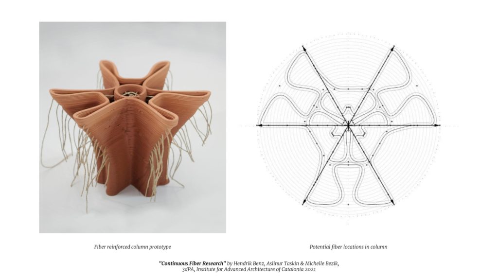
But when one looks for reinforced earth 3D printing, current literature is minimal to non-existent. The main source seems to be the previous 3dPA research, such as the Continuous Fiber research (Benz, Taskin, and Bezik 2021) that showed great potential in the improvement of the printability of unstable models through the addition of continuous fibre.
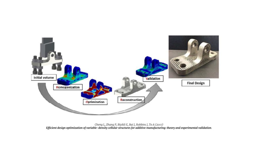
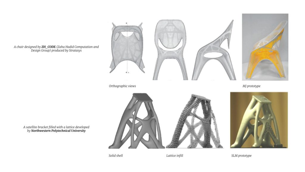
Structural optimisation in additive manufacturing
Following are a few projects in addictive manufacturing showcasing the potential and results of the use of topology-logical optimisation in fabrication.
Geometry Design
To start the research, a general understanding of the cantilevering capabilities of the material/scale/printer is needed. A small base geometry is chosen to start experimenting with. This single geometry will prove to be the starting point of the entire geometrical exploration during the research. (continued below in Reinforcement Strategies and Architectural Approach)
Inclination
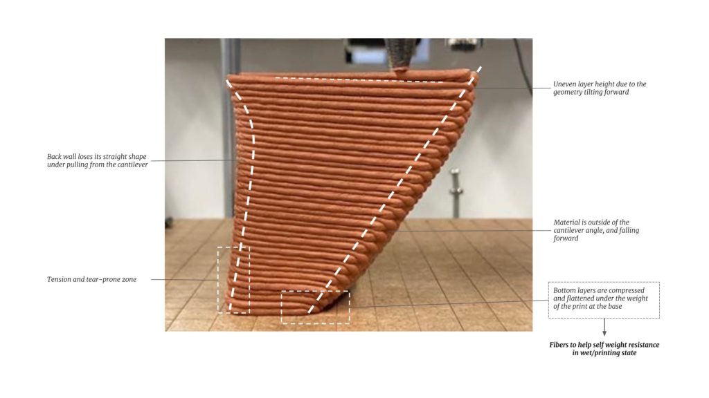
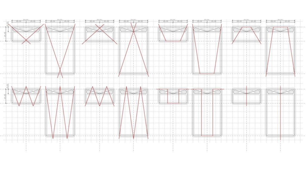
The base geometry is a generic 20x50mm base with a height of 100mm and cantilevers on one side. The infill is a simple triangle: to have a minimal infill without keeping the geometry empty & the cantilevering edge is not touched by the infill to better see its behaviour with the increasing cantilever angles.
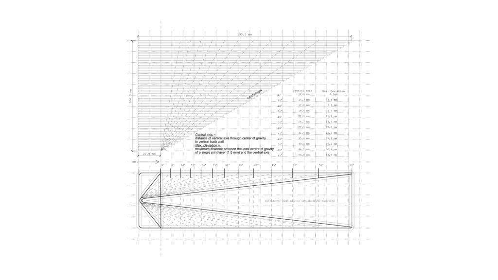
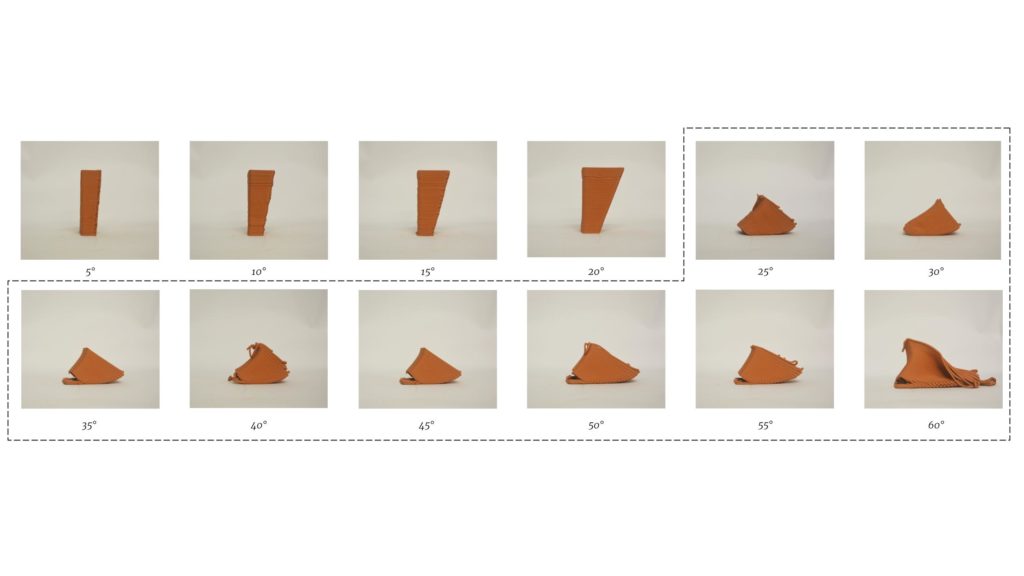
The print starts failing at the angle of 25°, as this is the first angle where the central axis lies outside of the base geometry.
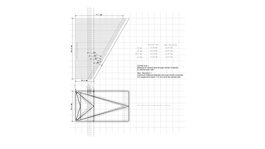
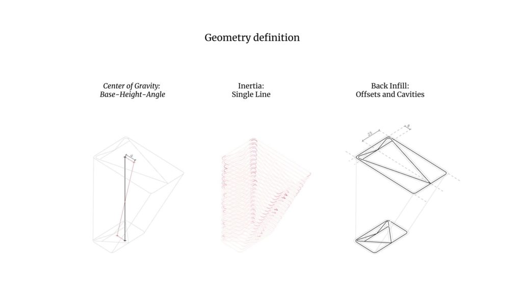
Central Axis
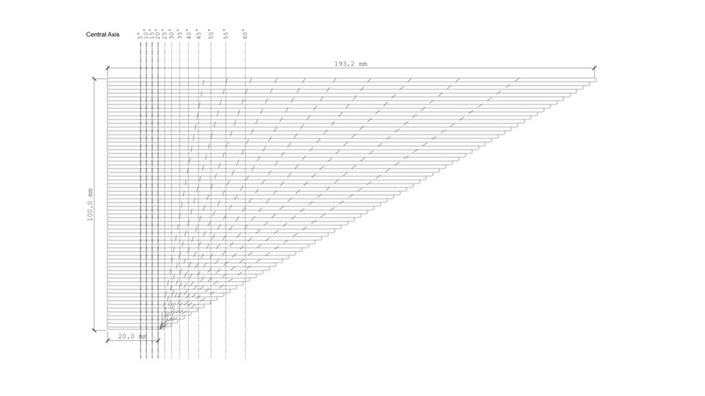
Definition Central axis: vertical axis through the average centre of gravity of each printing layer. This geometrical parameter informs about the global centre of gravity location.
As the Center of Gravity becomes the main obstacle of the leaning geometry, different infills are researched to place more mass at the vertical face of the model. The following design catalogue is drawn and multiple options are printed. The red cross on each print shows the centre of gravity projected onto the plan.
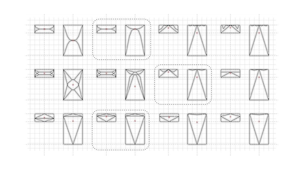
Geometrical limits
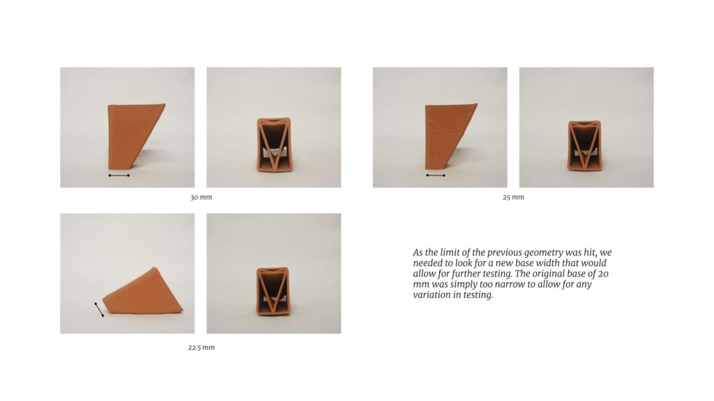
Although the geometrical central axis has become a key focus, the prints are still failing. Of course, the chosen base geometry is quite a counterintuitive approach as the single cantilevering geometry will always want to fall over. But the challenge of pushing the angle on a straight cantilevering surface is the main goal here. To overcome the failure of the prints, a decision is made to widen the base. The base was always kept to a slender 20mm, the idea is to create a cantilever with a small base. From previous printing, during the academic program, we know a larger base will allow for greater angles due to the surplus of material. Before enlarging the base, a few infills are tested again to move back the centre of gravity. Moreover, the toolpath length is one of the main parameters to choose the next infill with. Minimising the toolpath translates into using less material, which is in line with the idea to also minimize the base width.
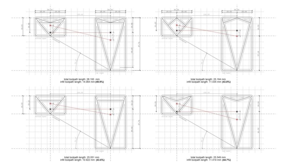
After testing and choosing a new infill, the base is slowly widened until a new width is found that allows for a stable 30° print. This ended up being 25mm
Conclusion
Some conclusions are made after the initial geometry testing, these are to be applied in the following chapters.
- The centre of gravity and its displacement are key factors to design a successful cantilever, as well as the mass of its infill.
- The local inertia, created by the contour lines of the geometry, is key for the deformation in both the wet and dry states.
- The large mass has to ensure minimal offsets between the different tangents in the infill. This has to be balanced with an appropriate distance for the designed cavities not to be filled up.
Fibre Material Properties
Natural Fibers
In line with the biomaterial approach of earth 3D Printing, the materials chosen to explore reinforcement are all natural fibres. Apart from the obvious environmental benefits (if fibres are sourced as locally as possible), logistical benefits could potentially arise. For the TOVA prototype (‘Prototype TOVA / Posgrado 3D Printing Architecture IAAC | ArchDaily’ n.d.), Sisal fibres are already integrated within the material system. It is easy to see how the same supplier could then be used for the different Sisal products. Or the opportunity to use Spanish cane for the rope (Couvreur and Buzo 2019), plays into the use of traditional building materials within an innovative additive manufacturing setting.
Fibre Strength
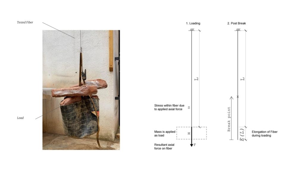
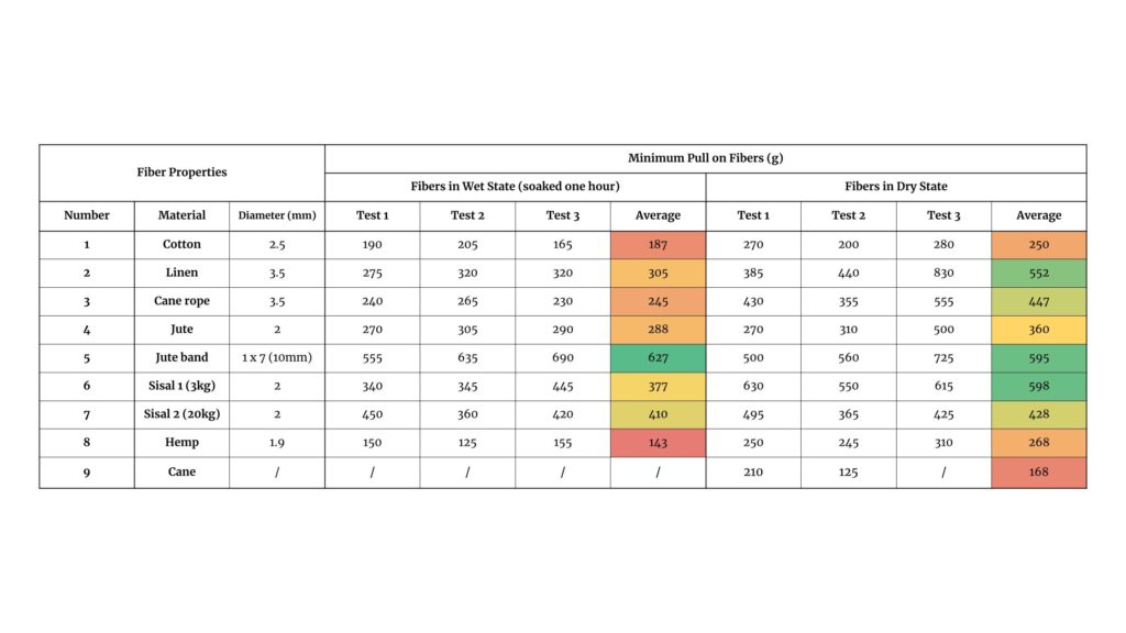
As a base material property, the axial strength of the fibre is tested. Although the research is not t a stage where the structural requirements on the fibres are defined, being able to classify the strengths and especially the elongation during loading are valuable base parameters. The tested fibres were selected on their natural materiality and on the availability and the time of sourcing during the test preparations.
Test Setup
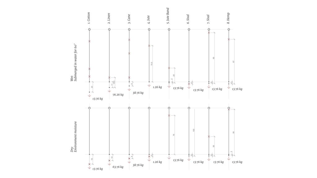
A 1 m long section of the fibre is tied up at a height of 2.3m. On the other end, two carabiners and a ratchet strap hook a 40L bucket onto the fibres, serving as a loading bay for the clay weight. Clay is loaded, in 12.5 kg increments and suspended for a set time in between load cases. Time, load and elongation at break are measured.
Results
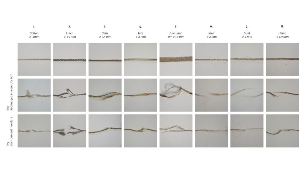
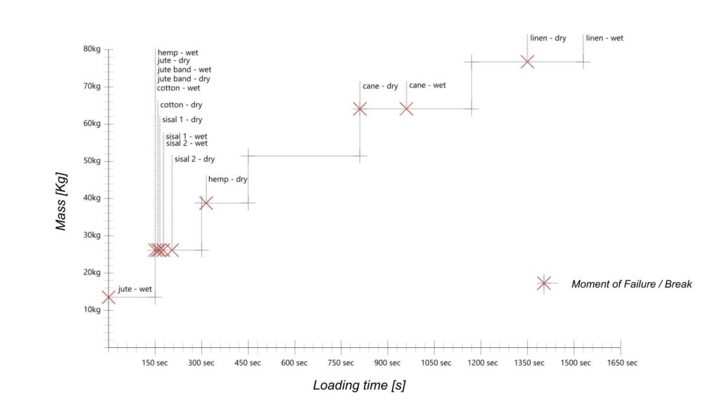
Each fibre (both in the wet and dry state) was only tested once, therefore the results are not as precise as intended. Linen was the strongest fibre both in the wet and dry state. While Jute was the weakest in both states.
The fibres were subjected to different load cases for specific time periods. The stepped loading (12.5kg increments) results in a different behaviour than a more gradual increase (> 1 kg-2 kg increments). The fibres have no time to adjust and stretch for the load increase. This loading method was the only possible with the setup but also relates to a sudden change of balance in a print.
All the fibres were tested in a dry state (outdoor conditions during testing) and a wet state (submerged for 60 seconds before loading). The wetting simulates a humid environment, such as the clay during printing. From our testing, there was no conclusive evidence that either state performed better.
But this is an interesting area (the change in material properties between wet and dry fibres) that deserves some further exploration
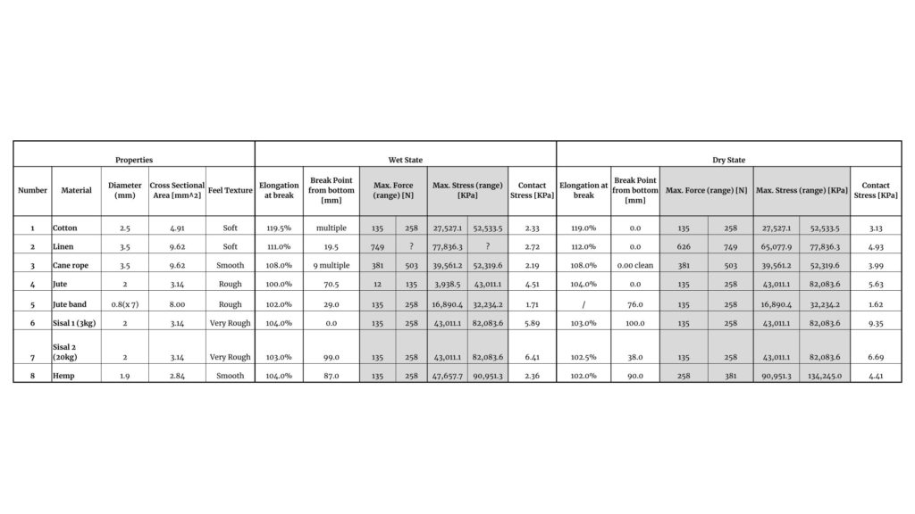
The maximum force pulling on fibre [N] (weight) F = m*g = m*9,8m/s2
The maximum stress in the fibre [KPa] Stress = F / Across section fibre
*cross sections were not adapted to the effect of elongation on the fibres
Fibre-Clay Adhesion
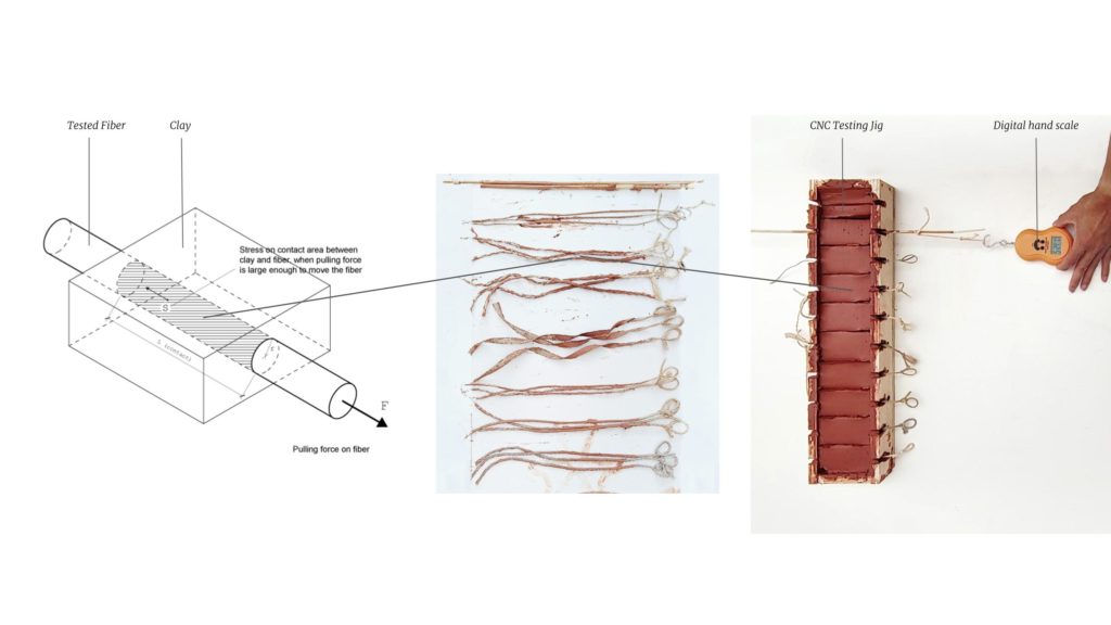
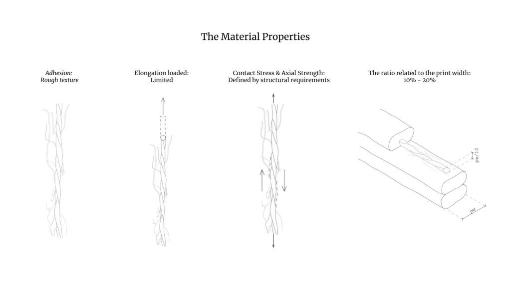
A crucial property to research is the adhesion between clay and the different fibres. As the main means of contact and attachment, material adhesion plays an important role in keeping fibres in place and restricting any slipping through the clay.
Test Setup
Using a digital scale, the fibres are pulled out of the clay. The mass on the scale at the time of the first movement (when the fibre starts sliding out) is recorded and later used to compare the fibres.
Results
Again, fibres are tested both dry and soaked (1 hour) to analyse different conditions and the influence of humidity on the material properties.
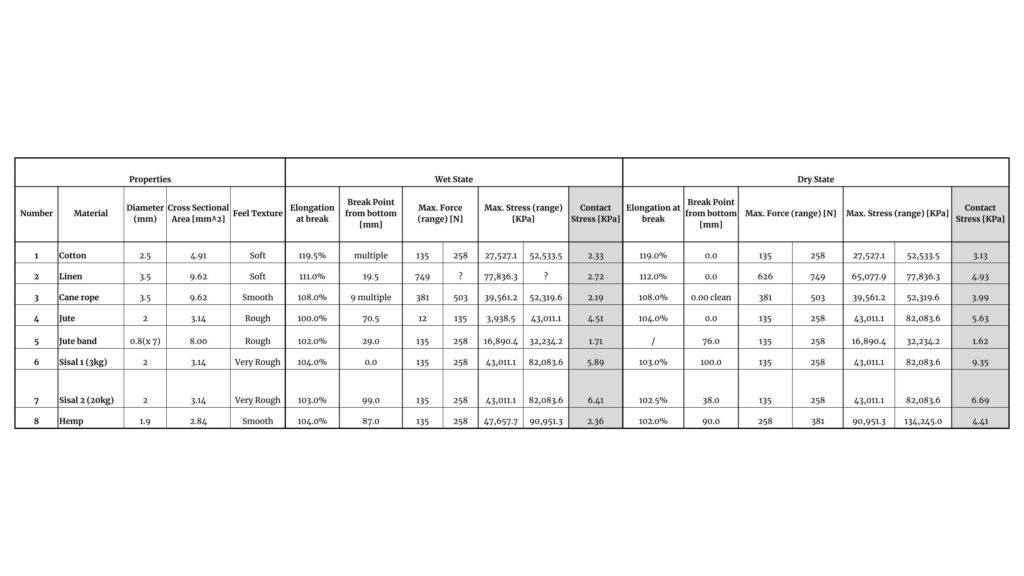
Contact stress between fibre surface and clay at first movement [KPa]
stresscontact= Fpull / Acontact surface= (Mpull, avg . a) / (Lcontact * 2pi* rfibre)
For the acceleration of the pull a, we used the gravitational acceleration g= 9,8m/s-2 to mimic a weight pulling down on the fibre.
Each fibre (both in the wet and dry state) was tested three times. The above “contact stress” is used to quantitatively compare the fibre taking into account the different diameters of the test samples. For the adhesion, as expected, there is a clear trend indicating that the dry fibres have better adherence compared to the wet ones. Sisal is the most adherent fibre, it is also the roughest one of all the tested samples. Less adherent fibres are cotton, cane & hemp.
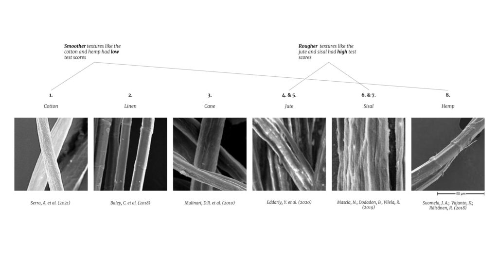
After analysing the test data, rougher fibres tend to adhere more to the clay.
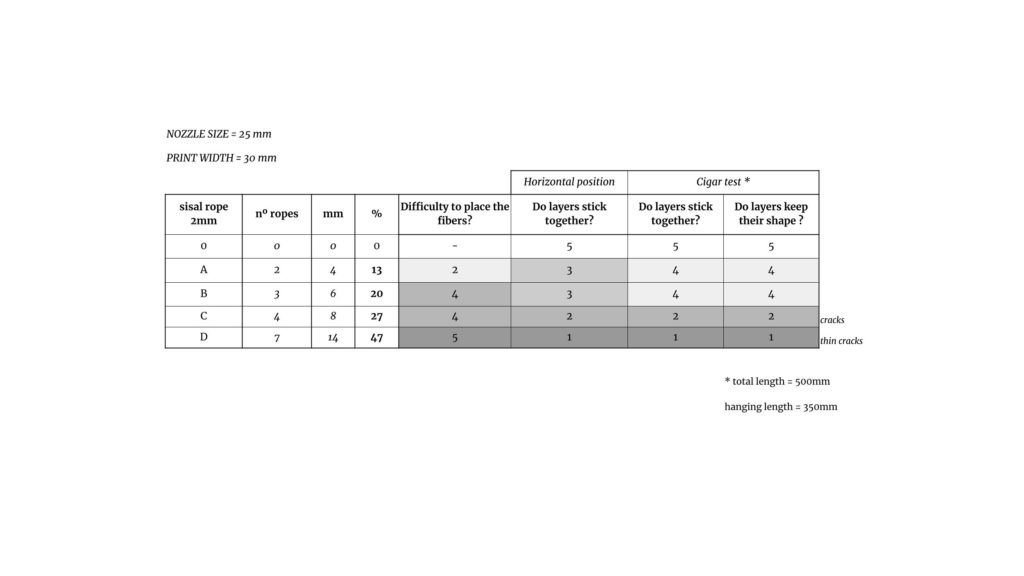
Fiber-Clay Ratio
To know how much fibre needs to be used, the ratio between the fibre diameter and print width is looked at.
Test Setup
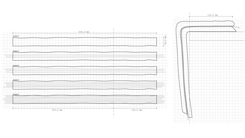
A cigar test is developed to test the cohesion between samples with different fibre ratios between them. On a table, a manual extrusion of the first layer of the sample is done. The fibre is placed on the printed layer before the second layer is extruded on top of the now fibre-embedded layer. The sample is moved to the edge of the table letting 15cm rest on it.
Results
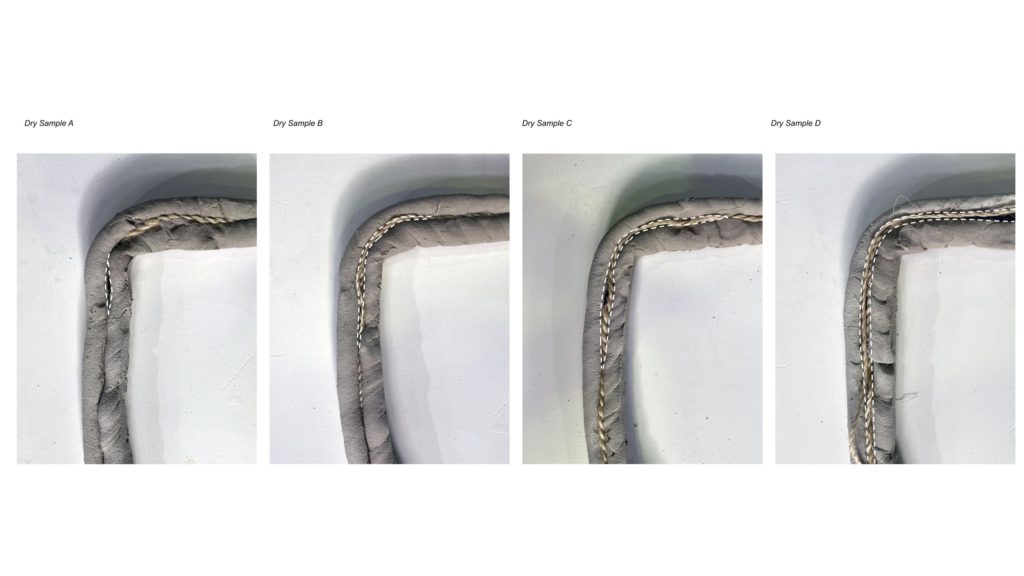
A max ratio of 20% (fibre to clay) seems to be the most effective at maintaining a good bond between layers. A different material was used as the material is pre-mixed and ready to print on a larger scale. Allowing the test to proceed with a consistency fit for printing
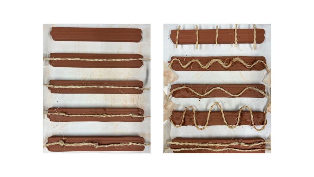
Fibre influence on shrinkage
The clay used during the research has a large shrinkage percentage of around at least 10% (value gathered from measuring prints during months of working with the material). Questioning the influence of a certain fibre layout within the clay seems an obvious step to take.
[some graphics in the following chapter might include the word retraction. It is in this case more appropriate to talk about shrinkage as retraction has other meanings in the field of 3D printing]
Test Setup
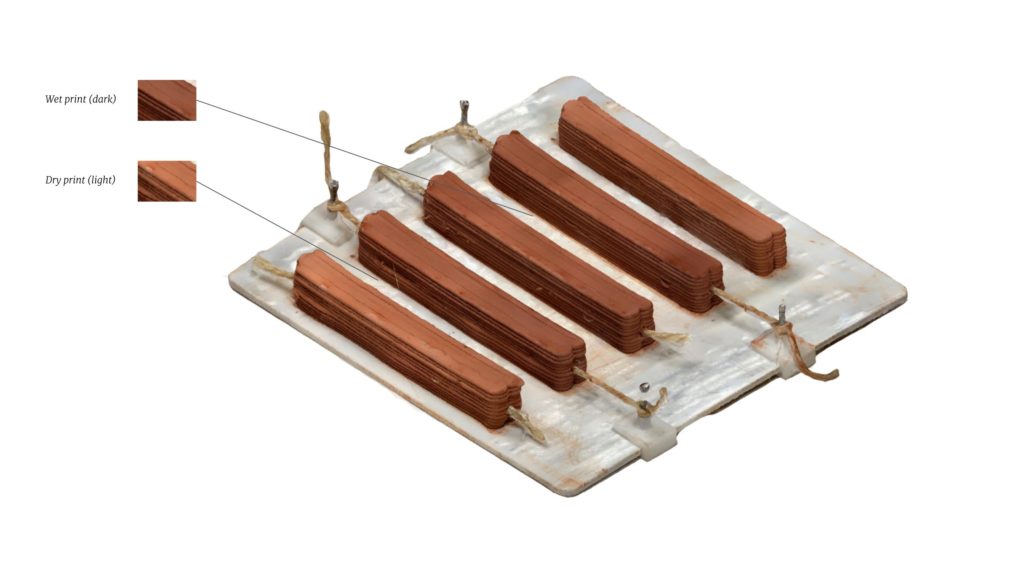
Various fibre layouts are compared regarding their effect on the retraction of the clay while drying. A 2mm sisal cord is used for its ability to ‘grab’ the clay due to its texture and its hydrophobic-like behaviour to avoid any influence on the water content while drying.
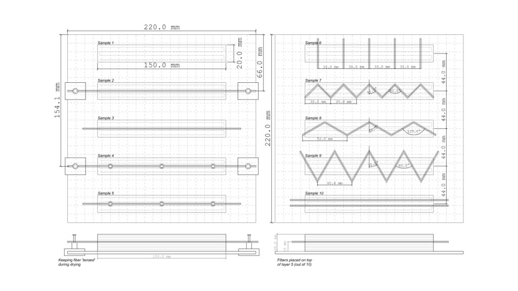
To monitor the shrinkage both photogrammetry and manual measuring with callipers were used. The photogrammetry allows a more detailed look at the shrinkage behaviour of the samples. Although the reliability and error margin depends on the quality of the scans and the scaling of the resulting point clouds.
Test Results
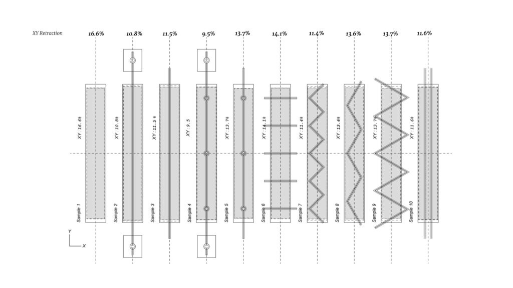
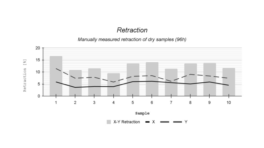
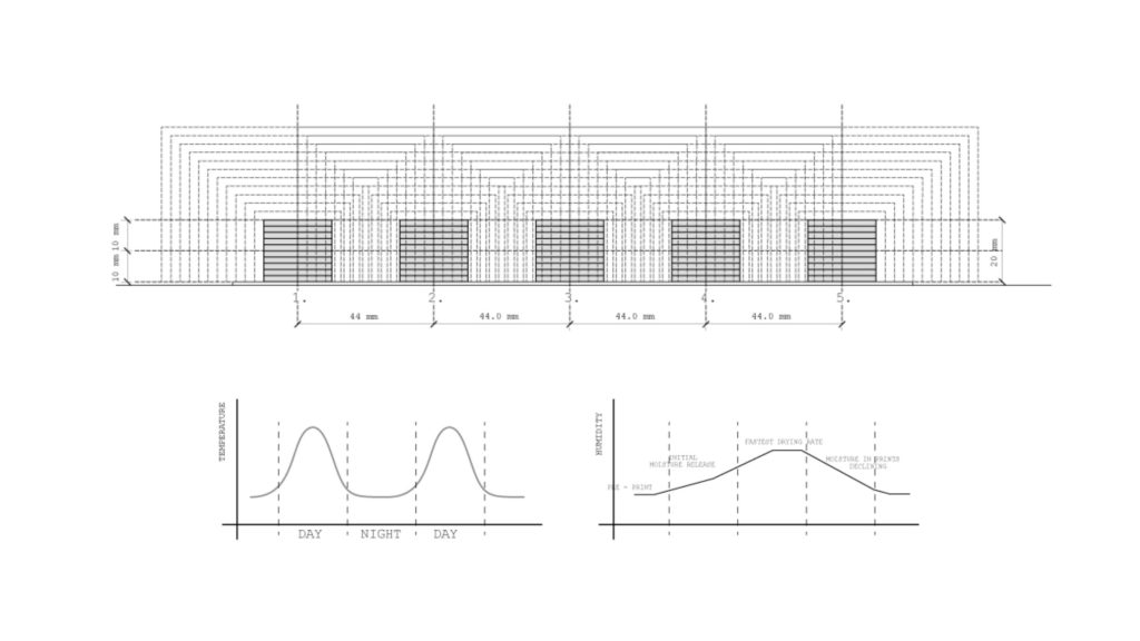
Using callipers to manually monitor shrinkage, the samples’ changes in dimension are compared. Only one sample per layout was tested, test results might thus be imprecise. Noticeable is that the retraction is greater along the length of the sample (Y-axis). Unfortunately, no further conclusion about the influence of the fibres during shrinkage can be made from this test. While analysing the results it became clear that the samples were too close together during the process and were affecting each other. This does teach us the importance of separating the test samples, and how clay’s drying process is affected when too much clay is in proximity to each other.
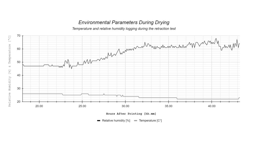
The proximity of the samples creates a high humidity area around the central samples while the outside samples have ‘free’ edges that are dried without added humidity from the other samples. While the temperature cycle is a ‘constant’ one, the humidity changes indicate a humidifier behaviour of the clay samples
Conclusions
The desirable material properties of the fibres are illustrated in the following diagram.
Reinforcement Strategies
Fibres
Earth as a building material has many climatic and environmental benefits. But it also has a few important structural restrictions: it should only be used in a compressive state and it is very heavy. To help take forces other than compression, mainly tension, the fibres are a perfect candidate to complement the earthen construction elements. Also, the
Introducing fibres in the prints
Before starting to add fibres into the print, a few boundaries have to be defined to restrict the potential fibre positions. The timeframe of the research does not allow for endless experimentation and thus the first boundary is that the fibre will only be allowed to work as planar additions to the print. Meaning that they will be positioned at a certain layer, and remain on that same layer. Secondly, the fibres will not be embedded within the printing path. This decision is made taking into consideration the final fibre placement, especially at the 1:10 testing scale, where it is very difficult to align fibres within the printing path. Third and last boundary, the research will look to take full advantage of the fibres during the printing phase. Therefore, the infill will be reduced/replaced and thus the models will remain as hollow and light elements. The outer edge will need work to reinforce the print, as concluded previously, but the central clay infill is not a research topic.
To start off with the first fibre layout testing, some catalogues were drawn according to the following principle: “In case you want to strengthen a structure with linear elements (e.g. fibers) align them with FF-lines to get the most effective layout.”(Preisinger 2021)
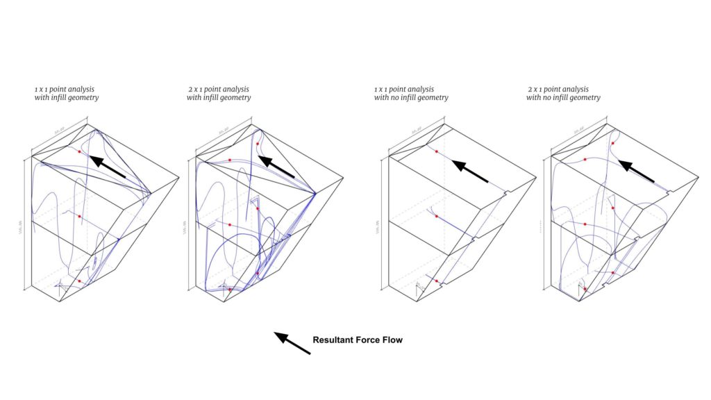
The quick Force Flow (FF) analysis above was done with Karamba3D (Preisinger 2013), grasshopper plugin, and shows us that the main FF lines for us to take into account run from the cantilever edge towards the vertical back wall. Knowing this, the following catalogues are drawn with fibre layouts that would, intuitively, help pull these forces from the front towards the back.
Before physically printing some options, there is the question of what happens in the area where the fibre meets the clay. We know that a maximum contact area between the materials is desirable, therefore a simple geometrical addition is added onto the thin front surface.
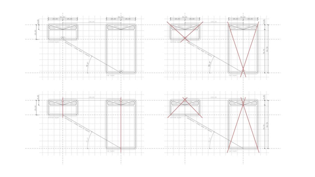
Not only does this addition increase the clay-fibre contact area, but these subtle markers also have the potential to become visual guide points for the placement of the fibres.
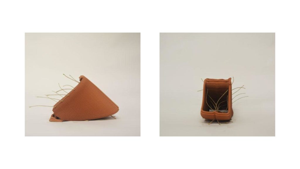
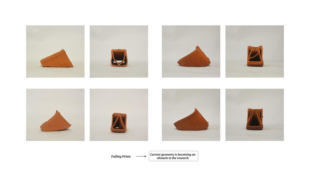
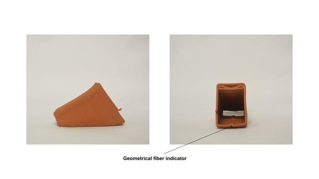
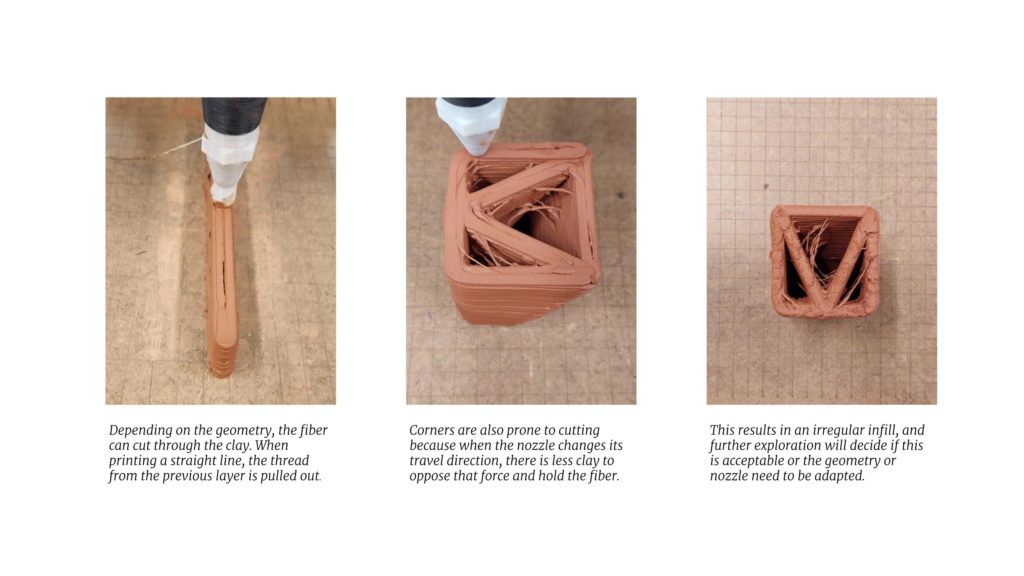
The failing model is again an indicator that the geometry’s limit is being reached. The potential to explore a new geometrical approach presents itself:
All previous prints are characterized by a rectangular outline and a certain infill pattern. The rectangle comes from the desire to create a consistent and wide cantilevered surface. While this approach seems somewhat counterintuitive to the weaknesses of 3D printing, this premise provides a challenging starting point. It is in this ‘triangular approach that we, for the first time, step away from the box and explore a different geometrical problem.
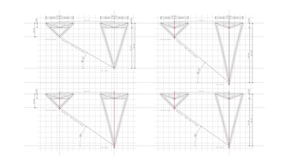
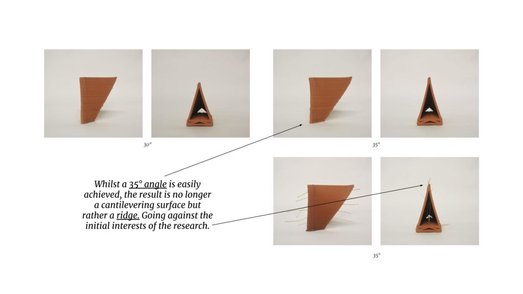
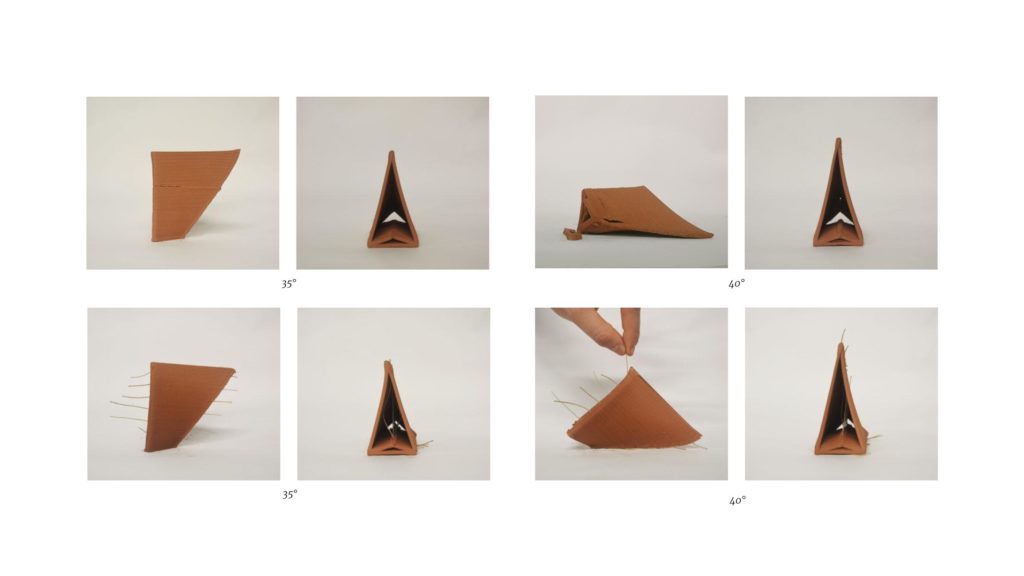
Due to the result being a ridge/edge instead of a surface, this geometrical approach was not further explored. Although taking away the rectangular contour and keeping the inner triangular infill is a nice way to cut down the overall mass of the model, the outcome was not satisfactory. The following steps include scaling up the module and replacing the inner infill with fibres. (see Module Arrays)
Manual versus automated placement
Some interesting research about simultaneous printing and reinforcement embedding has been conducted (Salet et al. 2018; Bos et al. 2017), following these examples some nozzles were designed and 3D printed (ABS plastic print).
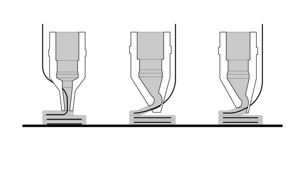
The designs referenced above illustrate the evolution of a concrete printing nozzle. To prevent the fibre from cutting the material as in the first iteration, a back-flow nozzle was developed, with the disadvantage of poor layer adhesion. The third iteration is a hybrid of the first two but needs an extra axis for aligning the nozzle to the printing path. (Salet et al. 2018)
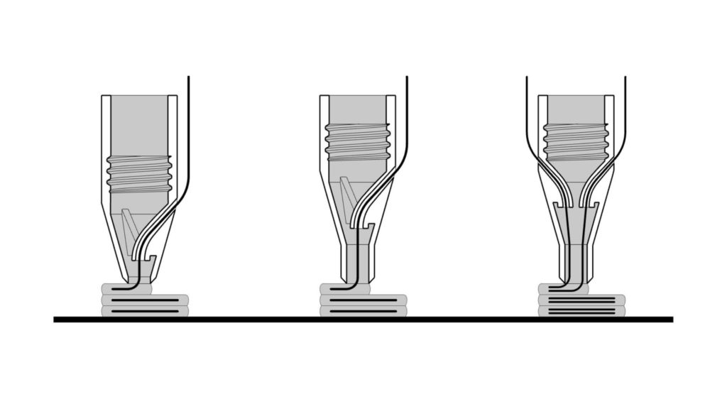
The proposed nozzle designs lay the fibres in the centre of the print lines, without the need for an extra axis. In the first iteration, the clay has poor pulling strength on the fibre, so the second one allows the clay to have a greater surface in contact with the thread while the tapered tip closes the gap generated by the tube. To further improve the pull of the clay on the fibres, the third iteration replaces the reinforcement flanges with multiple feeding tubes, further increasing the contact surface area between the materials.
The usage of these nozzles displayed quite a few difficulties when tested on a modified ENDER 5. The feeding of the fibre was a bit of a challenge, but more importantly, due to the fixed nozzle orientation, the fibre would get dragged through the clay during the printing process.
Ultimately the difficulties of the printing, and the expected difficulties when scaling up to the WASP Crane (‘Crane WASP’ 2022), put an end to the exploration of automated fibre placement. The approach as previously discussed, to add material and geometrical markers when to place fibres has the potential to create an easy-to-follow manual placing protocol based on visual guide points.
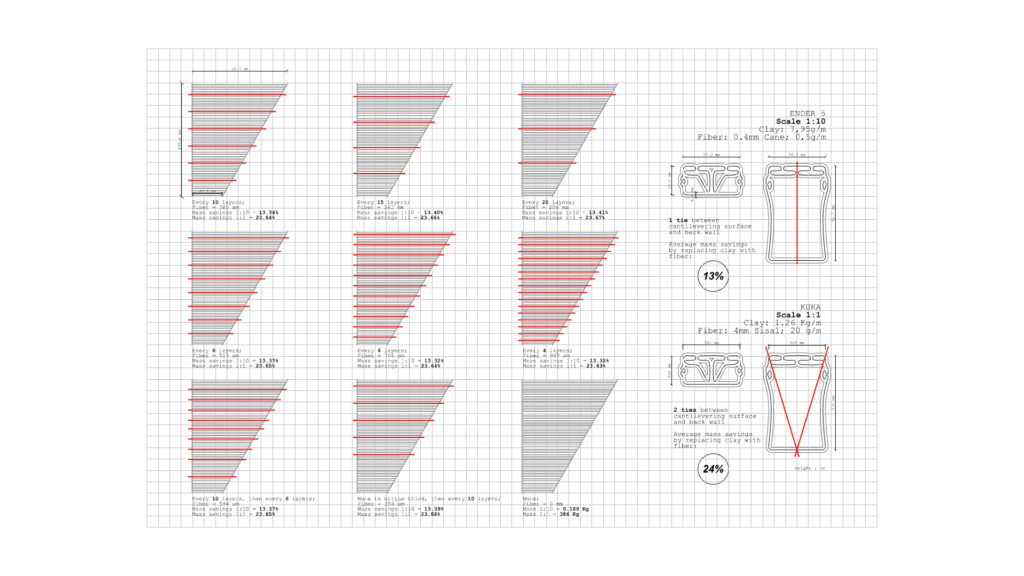
Mass savings through fibres
An important aspect of replacing clay infill with fibres is the potential mass savings that can be made. Two theoretical cases are compared to get an idea of the mass savings. Both cases are based on the tools and materials used within the 3DPA program at IAAC. Important to note that while the clay is needed on every layer, the fibres can be placed at an interval as they do not need to be fully supported except for the ends of the ties.
- Case 1: Single module printed on a 1:10 scale, with the Ender 5. Replacing the equivalent of 1 tie between the front surface and the back wall.
- Fiber mass = 0,5 g/m
- Clay mass = 7,95 g/m
- Average of 13% mass savings when replacing clay with fibre
- Case2: Single module printed on a 1:1 scale, with the KUKA KR 150 L100. Replacing the equivalent of 2 ties between the front surface and the back wall.
- Fibre mass = 20 g/m
- Clay mass = 1,26Kg/m
- Average of 24% mass savings when replacing clay with fibre
These numbers show an incredible potential to reduce the material usage (clay/earth) when replacing infill with fibres. Different frequencies of fibre placement barely make a difference when compared to each other (max. <0,2%), as the clay or earth makes up more than 98% of the total print mass.
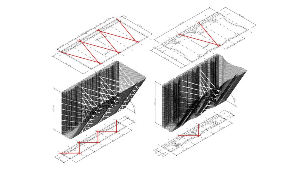
Module arrays
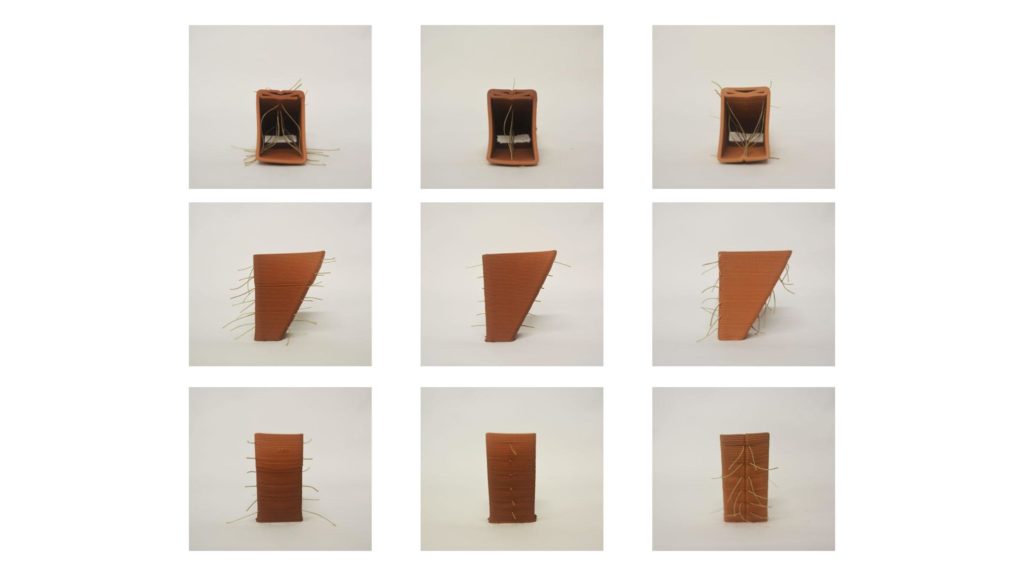
The previously explored single modules were limiting the research. They were both too limiting in their geometry as well as the fibres were barely needed to make a large difference. The choice to start working on a single module was to allow for growth in the print, as depicted below.
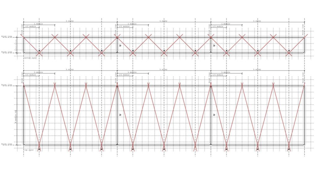
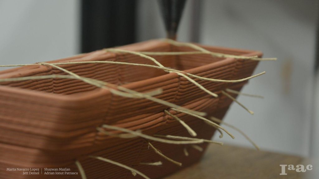
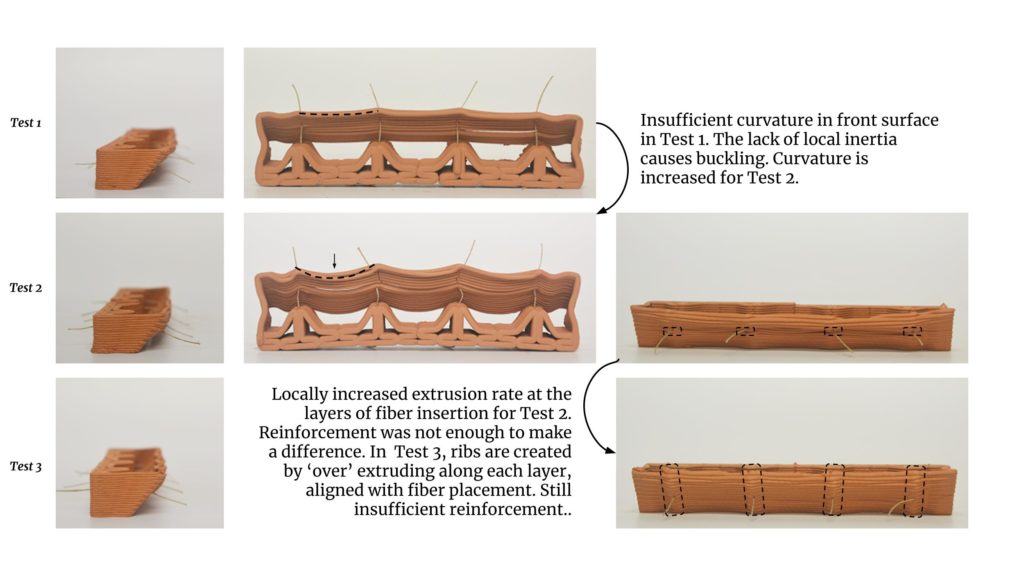
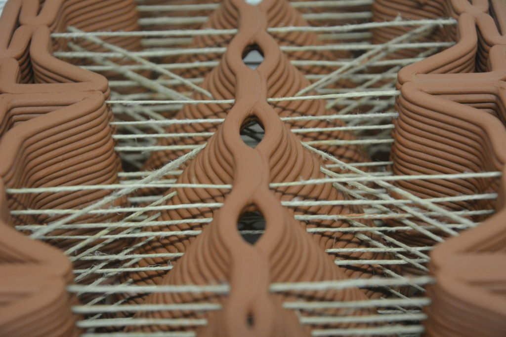
The first larger module printed is a triple module with the same toolpath as the single module. The scaling up was also the timing to keep the fibres straightened during the printing. A simple slotted jig, kept the fibres in place when extruded the first layer on top of them. Afterwards, the fibres were cut on both sides of the print, as the downwards-moving printing bed would otherwise rip the fibres out of the clay.
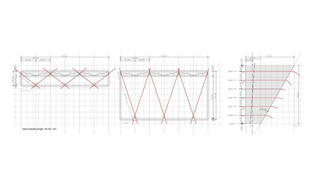
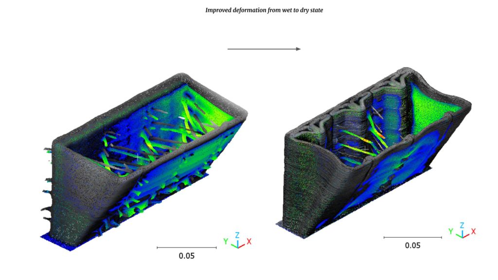
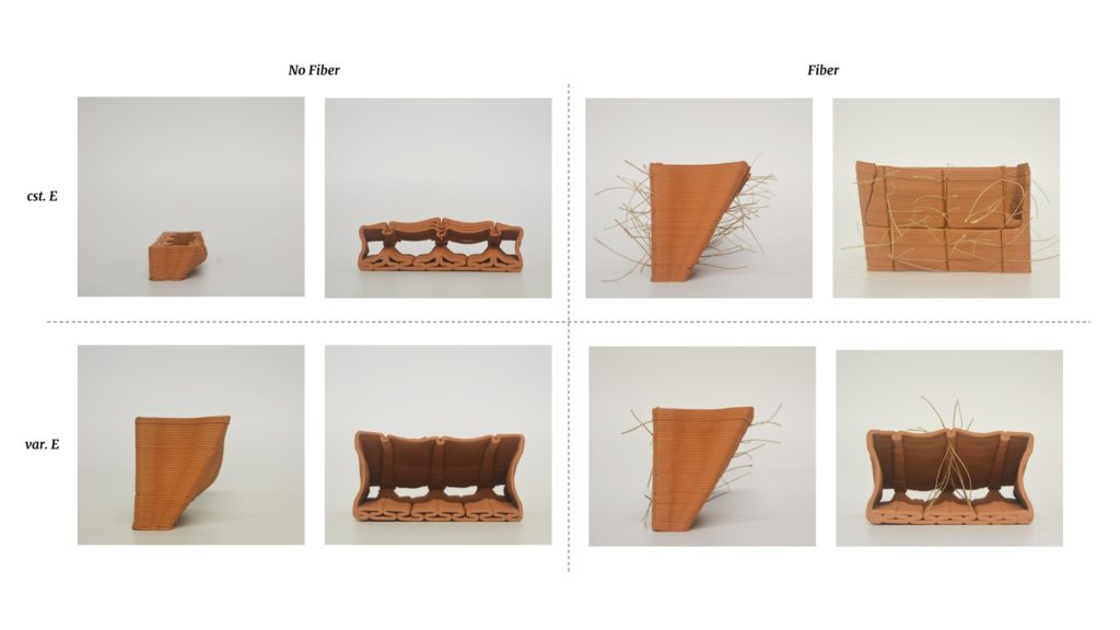
While fibre reinforcement made it possible to print the geometry to the desired height of 100mm, the same geometry without fibres only made it to 48.5mm before failure. After a few minutes of drying, the whole front of the model ripped and fell.
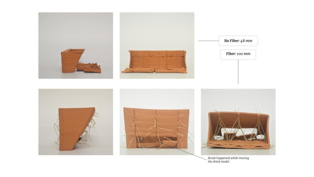
During printing, the added fibres helped tremendously to complete the print. Even after a bad section (due to new material loading, see picture below) the fibres stabilised the print.
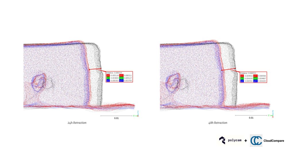
Through photogrammetry (Polycam mobile application) and point cloud comparing (CloudCompare software), the deformation between the wet state and dry state of the print can be monitored.
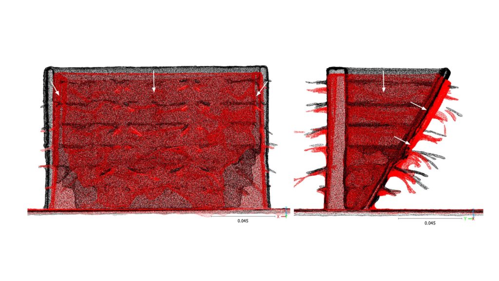
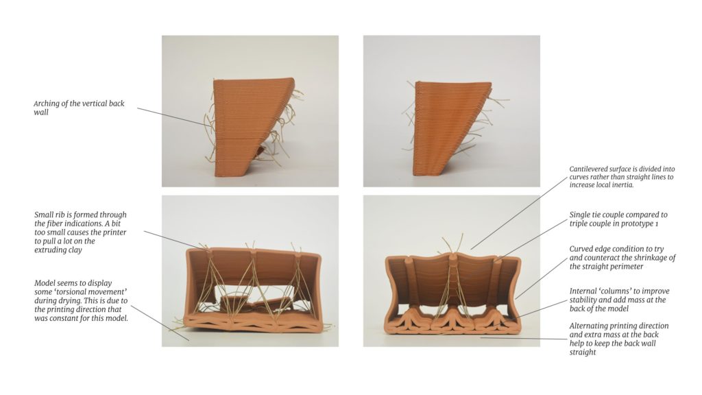
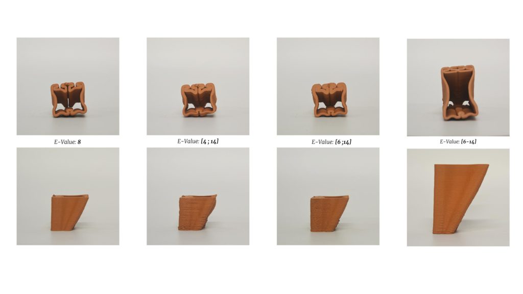
The deformation while drying, especially the buckling of the cantilever surface (see how red point cloud (dry after 20h) is falling outside of the black point cloud (wet after printing)) was not a satisfactory result. Although the advantage of fibres for improved printability was proven, the end result was too deform. A new design catalogue with improved geometries was thus made.
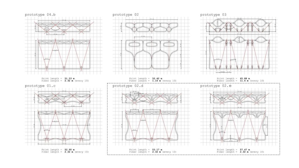
The improvements (annotated below) between prototype 1 (left) and prototype 2.e (right), were very promising. The deformation of the model was reduced, as intended, and the printing process was controlled much better.
Material Extrusion
One of the main advantages 3D printing has is the ability to only deposit material where needed. This geometrical freedom and high precision allow the creation of structurally optimized prints as demonstrated by the Block Research Group at ETH Zurich (Rippmann et al. 2018; Block, Rippmann, and Van Mele 2017). The strategy to structurally optimise the printed prototypes is explored through a variation in extrusion rate, also to be understood as the flow rate of the material. Instead of a geometrical strategy, the fabrication parameters are adapted to create variation in the material deposition. The following paragraph discusses the initial testing of these parameters.
Variable extrusion rate
To see the changes in print width for variable extrusion rates, a line test is done keeping the pressure and speed constant.
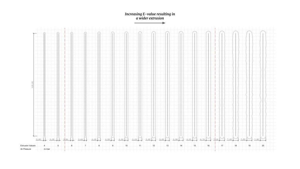
The range of extrusion rate values (E-Value) from 4 to 20 resulted in print widths ranging from 2,80mm to 7,90mm. This result confirmed that a variable extrusion rate could have a large effect on the material deposition and mass distribution of prints.
Edge length
Next the edge length or distance between consecutive control points/targets on the curves is modified. This parameter has an effect on not only the resolution and quality of the final print but also affects the printing speed and extrusion. If the edge length would be too small the motors of the printer might not have enough time to adjust their position, resulting in some targets being missed or the printing speed would need to decrease. For robotic fabrication, too many targets would result in very heavy G-Code files and slower printing as the robot needs more time to read all the commands (depending on robot’s capabilities)
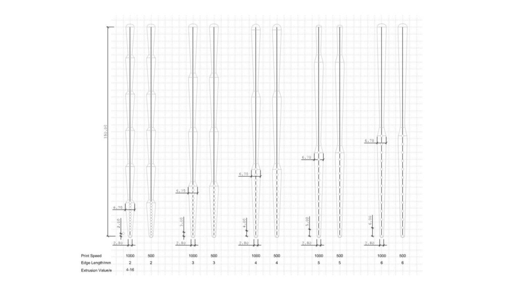
The test uses 1000 and 500 print speeds and the result of both printing speeds is quite similar on this printing scale, which is proved that print speed does not have a big influence on the changing of e value. And then even for the smallest tested edge length, the motors had enough time to adjust their positions and step number.
Locally applied extrusion rate variations
Following are early tests to change the E-value in a designated zone of the print. The range of values is found through the previous line test. This type of quick line test is needed and recommended when changing printing setups or for the material. We were also able to locally increase the E-Value in singular targets, useful to increase the amount of clay in locations where fibre comes in contact with the clay.
Advantages of the reinforcement strategies
Having proven the ability to control the extrusion rate to vary the printing width, this now needs informed inputs. Karamba3D is used to minimise the displacement of the geometry resulting in the input data for the extrusion rate for each individual target in the print. As 3D printing is a layered fabrication method, each layer can be seen as a cross-section. These cross-sections are then optimised to be wider where more material is structurally needed (and thinner where the structural requirements allow it). See Computational Workflow and Toolkit for the breakdown of this process.
With such positive results, the jump is made to a quadruple model. Pushing the maximal width of the printing bed, this module also pushes the cantilever angle to 40°, a feat that was not possible without a full variable extrusion rate.
The first tests were not successful, but when introducing a full cross-section optimisation, the print was successful. Proving the validity of the reinforcement strategy.
In order to optimise the positioning and density of the fibres, Karamba3D is used to analyse the digital model. The buckling factor and the maximum displacement of the geometry are used as objectives to optimise the fibres introduced in the geometry. See Computational Workflow and Toolkit for the breakdown of this process.
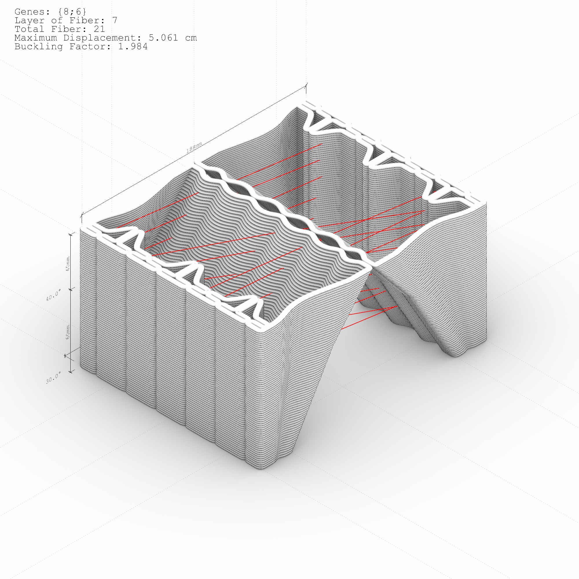
Two prototypes are tested following the results of the computational analysis.
The prototype with distributed fibres performs better than the one where the fibres intersect in one point. The intersection of different fibres increases the fibre ratio in the point making it weaker.
Architectural approach
Space Generation
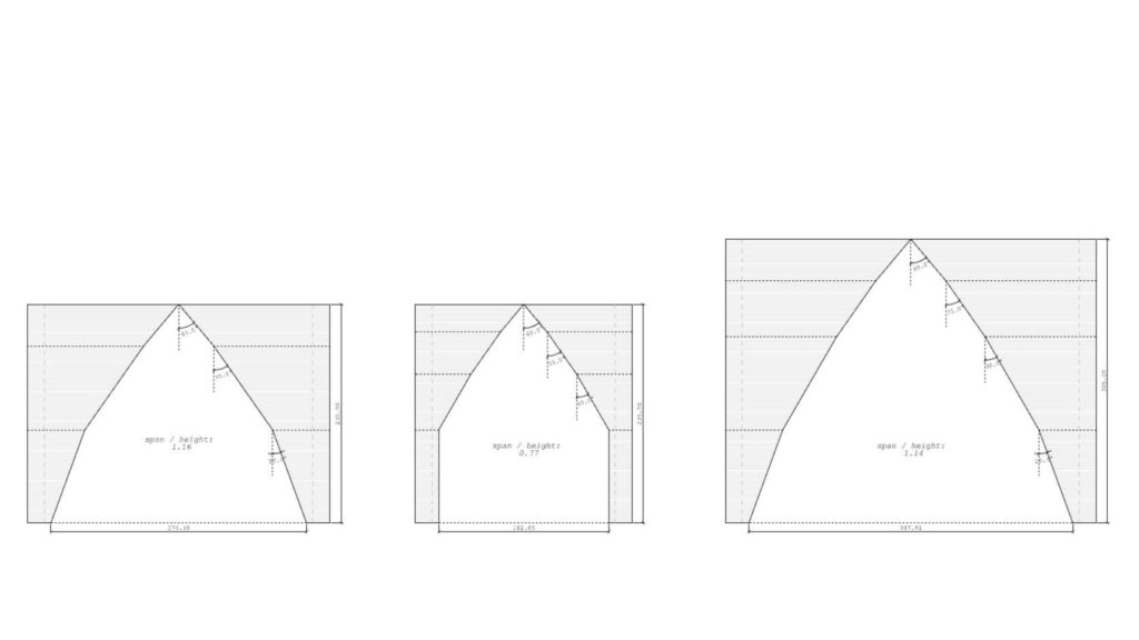
The developed system is applied to enclose a space. The challenges are reaching higher geometries and joining two symmetrical walls. The space created is defined by the segmentation of the cantilever angle.
Angle Variation
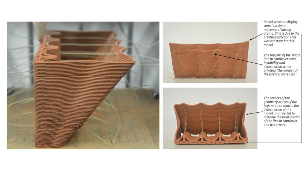
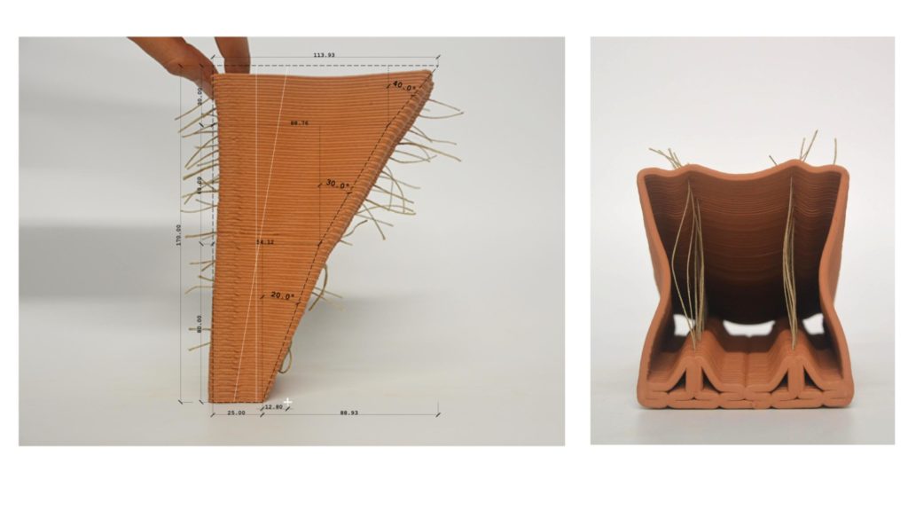
To test the cantilever angle segmentation a single-column test is conducted. A double module geometry of 17cm height is tested to achieve a span of 8,8cm. The base of 2,5cm starts with a 20 degrees cantilever, continues with a 30-degree angle and ends with a 40 degrees cantilever. The deformation of the geometry is larger in the higher layers due to centre of gravity displacement. Therefore the density of the fibres is increased in the higher cantilever angles. The model turned unstable during the drying process demonstrating that the limit of the geometry has probably been reached.
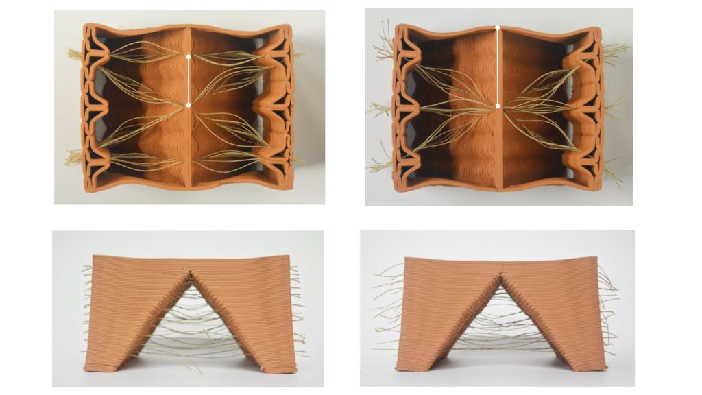
Enclosing the space
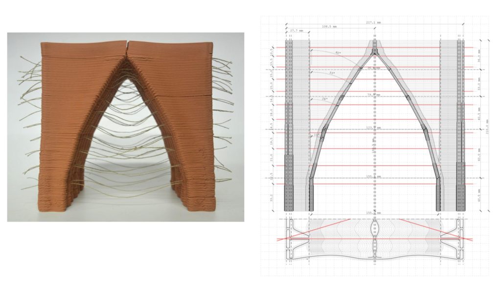
The same column is tested mirroring the geometry and creating an arch. In this case, the digital model of the geometry is analysed to define the variable cross-section, giving additional mass to the base. Therefore the deformation of the model is less noticeable in the bottom layers. The placement of the fibres follows the digital model analysis. The contact point of the cantilevers is tested as well, which is a challenging design itself.
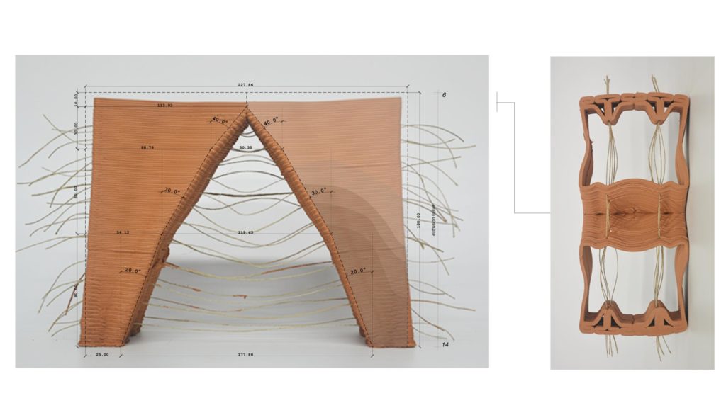
The limits of the system are tested in a bigger prototype of 22cm in height. In this case, the base is enlarged to 3cm and it starts with a straight extrusion in the base and ends with a 40 degrees cantilever angle. The extrusion value is variable using the explained methodology, and it varies from 3.5mm to 5.9mm. The fibre direction and position are optimised following the toolkit set-up. The prototype keeps its stability during the printing process, and the connection of the two cantilevers is the weak point after drying. Probably, the asymmetrical drying process of the two parts of the structure and their independent deformation make the joint one of the most brittle parts of the structure. The solution of the top is a key point to be developed in further research.


Speculations on scaling up
Although the main research goals are focused on small-scale printing, some experiments were set to understand which are the constants and variables when the geometry doubles in size. This provides some insight into what could be expected when moving on to an even larger scale.
As all the previous printing was done only in the horizontal plane, the methodology is compatible with the crane printer, which can also vary the extrusion rate.
The jig can easily be replaced by an attachment of the fibres to the previously printed layers to keep them in place and straight during the printing process.
Other material tests should be carried out for the performance of the earth and its relationship to different fibres, but in order to find the limits of the large-scale print, the same presented methodology needs to be applied.
For the medium scale, we used a robotic arm, at first only adapting for the new equipment by changing the feed rate instead of the flow rate to print geometry with varying thickness. The same line printing tests were performed to find the speed and pressure balance that would result in the required print width.
At first, all the parameters were doubled and after failing, we became more conservative with the cantilever angles and used more fibres than in the small-scale trials.
Computational Workflow
The validated strategy is systemized. Design parameters such as fibre placement or cross-section optimization are parametrized by the structural analysis.
The fibre position is found using an Evolutionary Algorithm. By minimising the displacement the final outcome is the optimised fibre placement system.
The digital structural analysis of the reinforced geometry informs the mass distribution of the printable geometry. The cross-section thickness of the analysed mesh is optimised by using a Karamba component.
Toolkit
GitHub link coming soon (GDrive)
Further Development topics
The focus of the present research is the development of a reinforcement system for the wet state of a cantilever geometry. The two main strategies are print cross-section optimisation and fibre introduction and placement optimisation. Once the system has been developed, tested and analysed a toolkit has been set. Using the system a design exploration has to be fully developed to enhance the results of the research. Therefore, the applicability and adaptability of the system to different architectures and geometries are still paths to be further explored.
Additionally, the scalability of the system has to be fully researched after the conclusions of the ABB prototype.
Likewise, the next steps include the exploration of the attachment of the fibre in the walls, as well as the systematisation of their placement in the different scales and applications.
Conclusions
The strategies set for the research development have been successfully proven as valid measures to improve the stability of 3D printed structures during the wet state. The printability of the structures has been improved reaching higher cantilever angles while maintaining slender geometries.
As a massive construction system, the weight of the 3d printed earth structures is sometimes their own limitation. The optimisation of the material placement through the variable cross-section of the print has demonstrated that there is still a clear opportunity to improve 3d printing construction performance. The adaptability and flexibility of the construction system allow it to easily integrate the material optimization strategy, changing each point print width as needed. Therefore the mass can be minimised and placed where it is needed.
The fibre introduction in the geometries follows the same strategy of minimising the mass and weight print. It has been proved that replacing infill with fibres helps to stabilise the geometry.
The combination of both strategies has set a promising step to optimise 3d printed structures. When it comes to large structures and cantilever geometries, the optimisation of the construction system is key in ensuring its feasibility. Minimising mass and ensuring stability while printing have been revealed as promising replicable outcomes for any type of 3d printing construction.
Bibliography
Benz, Hendrik, Aslinur Taskin, and Michelle Bezik. 2021. ‘Continuous Fiber Research’. Institute for Advanced Architecture of Catalonia (IAAC).
Block, Philippe, Matthias Rippmann, and Tom Van Mele. 2017. ‘Compressive Assemblies: Bottom-Up Performance for a New Form of Construction’. Architectural Design 87 (4): 104–9. https://doi.org/10.1002/ad.2202.
Bos, F.P., Z.Y. Ahmed, R.J.M. Wolfs, and T.A.M. Salet. 2017. ‘3D Printing Concrete with Reinforcement: 2017 Fib Symposium, June 12–14, 2017, Maastricht, The Netherlands’. Edited by D.A. Hordijk and M. Lukovi?. High Tech Concrete: Where Technology and Engineering Meet, 2484–93. https://doi.org/10.1007/978-3-319-59471-2_283.
Classen, Martin, Jan Ungermann, and Rahul Sharma. 2020. ‘Additive Manufacturing of Reinforced Concrete- Development of a 3D Printing Technology for Cementitious Composites with Metallic Reinforcement’. Applied Sciences 10 (May): 3791. https://doi.org/10.3390/app10113791.
Couvreur, Lucile, and Alejandro Buzo. 2019. ‘Construir con caña. Estudio del uso de la caña en la arquitectura tradicional y de su recuperación para la construcción contemporánea’. IPCE – Instituto del Patrimonio Cultural de Espana. http://todopatrimonio.com/publicacion-ipce-construir-cana-estudio-del-uso-la-cana-la-arquitectura-tradicional-recuperacion-la-construccion-contemporanea/.
‘Crane WASP’. 2022. WASP. 2022. https://www.3dwasp.com/en/3d-printer-house-crane-wasp/.
Gantner, Stefan, Philipp Rennen, Tom Rothe, Christian Hühne, and Norman Hack. 2022. ‘Core Winding: Force-Flow Oriented Fibre Reinforcement in Additive Manufacturing with Concrete’. In Third RILEM International Conference on Concrete and Digital Fabrication, edited by Richard Buswell, Ana Blanco, Sergio Cavalaro, and Peter Kinnell, 391–96. RILEM Bookseries. Cham: Springer International Publishing. https://doi.org/10.1007/978-3-031-06116-5_58.
Preisinger, Clemens. 2013. ‘Linking Structure and Parametric Geometry’. Architectural Design 83 (2): 110–13. https://doi.org/10.1002/ad.1564.
———. 2021. ‘3.7.13: Line Results on Shells’. Karamba 3D Manual 2.2.0. 2021. https://manual.karamba3d.com/3-in-depth-component-reference/3.6-results/3.6.12-line-results-on-shells.
‘Project A 05 – Additive Manufacturing in Construction (AMC) TRR277’. n.d. Accessed 13 December 2022. https://amc-trr277.de/projects/project-area-a/focus-area-project-a05/.
‘Prototype TOVA / Posgrado 3D Printing Architecture IAAC | ArchDaily’. n.d. Accessed 14 December 2022. https://www.archdaily.com/988078/prototype-tova-posgrado-3d-printing-architecture-iaac.
Rippmann, M., A. Liew, T. Van Mele, and P. Block. 2018. ‘Design, Fabrication and Testing of Discrete 3D Sand-Printed Floor Prototypes’. Materials Today Communications 15 (June): 254–59. https://doi.org/10.1016/j.mtcomm.2018.03.005.
‘Rock Print’. 2015. GramazioKohlerResearch. 2015. https://gramaziokohler.arch.ethz.ch/web/e/projekte/297.html.
Salet, Theo A. M., Zeeshan Y. Ahmed, Freek P. Bos, and Hans L. M. Laagland. 2018. ‘Design of a 3D Printed Concrete Bridge by Testing’. Virtual and Physical Prototyping 13 (3): 222–36. https://doi.org/10.1080/17452759.2018.1476064.
Wu, Zhengyu, Ali M. Memari, and Jose P. Duarte. 2022. ‘State of the Art Review of Reinforcement Strategies and Technologies for 3D Printing of Concrete’. Energies 15 (1): 360. https://doi.org/10.3390/en15010360.
