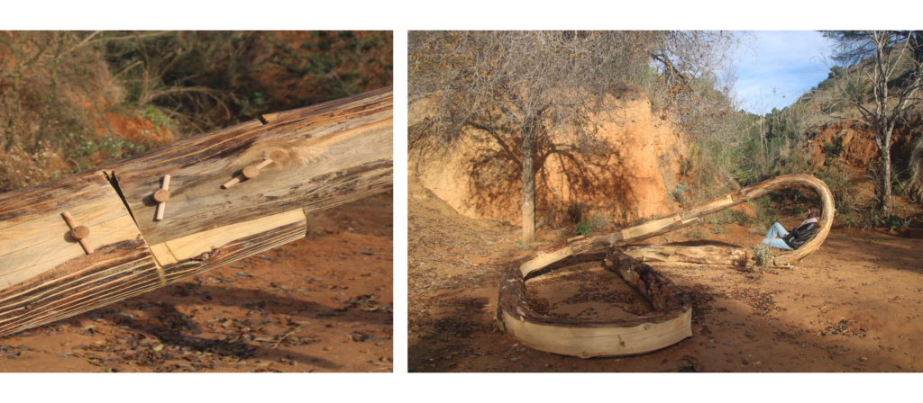
The project ‘[Wood]le’ – a ‘Wooden Noodle’ explores the idea of steam-bending tree logs to create a self-stable structure. The Woodle assumes the function of a seating area as it rests on the ground at one end and folds up to become an element that frames the valley of Font Del Gos on the other.
The project was developed over a period of a month through iterative cycles of material prototyping and digital modeling & scripting to define and re-define workflow. The project’s salient feature is to connect the tree logs as an infinite loop which stabilizes and maintains the tension in the bends. The infinite loop consists of 6 members; 5 bent and 1 straight.
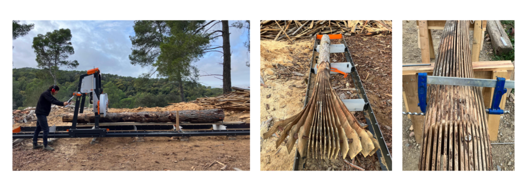
Fabrication began by exploring the possibilities and methods of log bending. We started by making slices in a log on the sawmill in order to see how flexible the log became once the slices were made. We were intrigued with the lamellae made by slicing the log and began exploring how we could connect two logs by intersecting the lamellae.
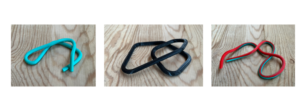
The design evolved to be a continuous loop of logs being bent and connected as necessary. We 3d printed small-scale models to help us visualize and further develop the design.
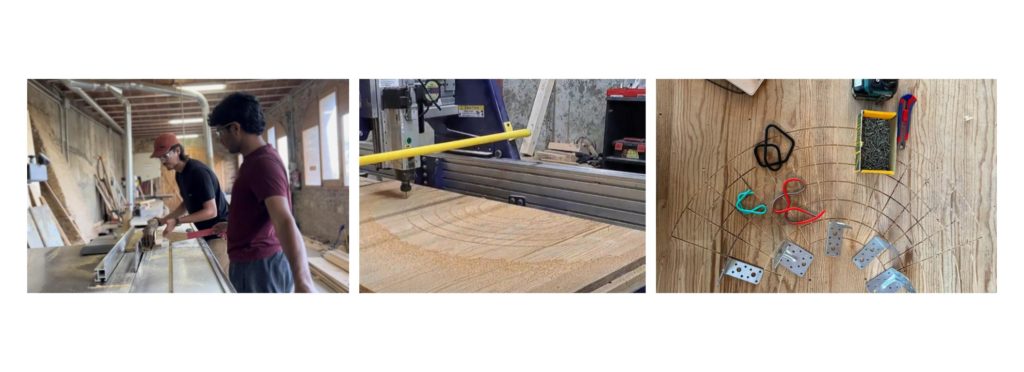
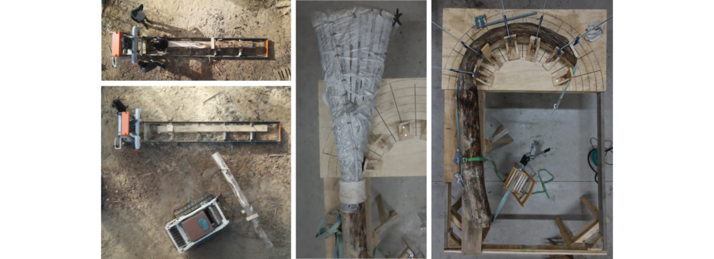
In order to better understand how the logs would fit together and to attempt steam bending, we built 1:5 prototypes. We first needed to slice the smaller logs using the table saw and then we created a jig to bend the logs by using the CNC to engrave an array of radii into a plywood sheet in order to control the radius of the bend more accurately.
Our first 1:5 steaming and bending was successful, although we needed to figure out better ways to apply force to the log in order to more efficiently bend. After bending our first couple of logs we experimented with the joinery by inserting wooden dowels into the lamellae to see how well it would retain the bend.
We produced more 1:5 prototype bent logs in order to create a prototype that was a fully connected loop. Our desired form was not achieved, in part due to a lack of precision regarding the length and radius of curvature for each log, but we were still able to create a continuous loop.
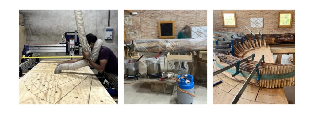
We then translated our experiences from the 1:5 prototyping to 1:1 prototyping and to the fabrication of the final logs. We created a full-size jig using the CNC to engrave radii on a plywood sheet which was supported by five wooden sawhorses. We used the original 1:1 prototype sliced log to attempt steaming and bending at the full scale.
After bending the 1:1 prototype log, we left it on the jig and clamped for at least 24 hours. We released the log from the straps and clamps to see the amount of rebound, which was significant. This observation informed us that we will need to keep the logs in shape with a tension strap until the time of assembly.
Due to time constraints, we needed to begin preparing the final logs. We calculated the overall length, the slice length for each end, and the radius of curvature for each log with the help of a script developed in Grasshopper.
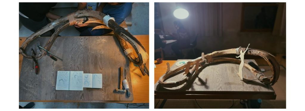
In tandem with preparing the final logs, we needed to better understand how the joinery would work and if the idea to intersect the lamellae of connecting logs would be viable. We used the bent 1:1 prototype to attempt connecting with another sliced, straight log. We wanted to simulate the real conditions as close as possible; with the short, sliced ends of our final logs being sliced to about 50 cm, we needed to keep this in mind with our joinery prototyping.
Aligning the lamellae of each log proved to be quite difficult with the bent log and the short 50 cm length of slits on the straight log. We tried using a CNC produced comb to evenly spread out the lamellae and slide the logs together, but the plywood comb proved to be too weak and would break as we tried hammering it in between the lamellae.
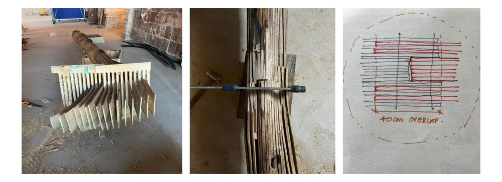
Ultimately, during our assembly simulation we realized that we would need to further simplify the final joinery. We adapted the 1:1 joinery prototype to be an open mortise and tenon joint. Instead of intersecting the straight log lamellae, we cut off the end lamellae so that the end lamellae of the altered log would align to the notch of the straight log, as shown in the sketch below.
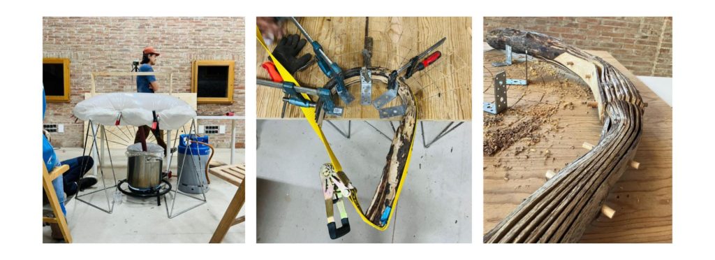
The final log fabrication followed the same steps as the 1:1 prototype. We sliced the logs on the sawmill, used the bobcat to transport the logs, steamed the logs, and bent them on the jig.
Our steaming setup for the final logs included a small steam machine along with two pots heated by propane burners. After the log was bent, we left it on the jig for at least 24 hours and then used ratchet straps to wrap around the log and hold it in its shape until assembly.
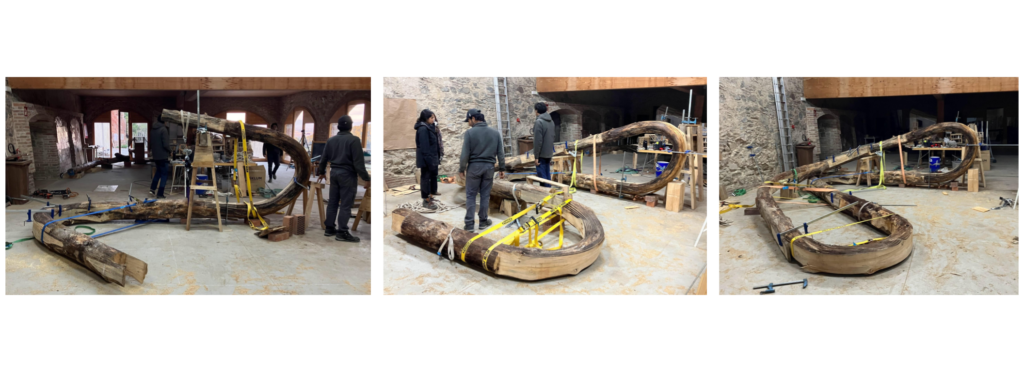
Once all the logs were sliced, steamed, and bent, we had an assembly simulation in order to see how the logs would join together and form a loop. We realized that due to an insufficient bend in one log, we needed to adjust our design to achieve the closed loop. Ultimately, the final form more closely resembles the 1:5 prototype rather than our intended form.
In order to brace the vertical portion of the loop, we built a large sawhorse for the vertical log to be supported by while the rest of the loop was assembled. We used straps and clamps to adjust the form as necessary. The loop proved to be quite stable once it was fully connected.
A large truck with a crane was used to transport the logs to the site. We used the same methods from the assembly simulation to assemble the [Wood]le on site.
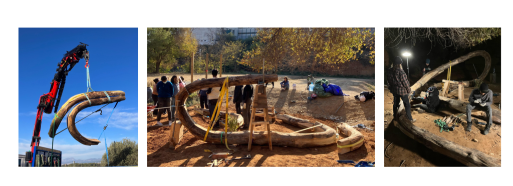
We used wooden dowels to connect the logs and lamellae. On each dowel end, the dowels had a smaller dowel drilled through to ensure the lamellae were held in place.