Objective
The objective of this course is to design and evaluate a lattice pavilion structure using computational geometry and structural optimization. This post presents the complete design workflow, beginning with the geometric definition and structural analysis of the system as both a shell and a lattice. It then discusses the various outputs generated by the Crystallon Cell Selector, followed by an overview of the optimization strategy. The post concludes with a brief discussion on 3D printing and fabrication considerations.
Geometry
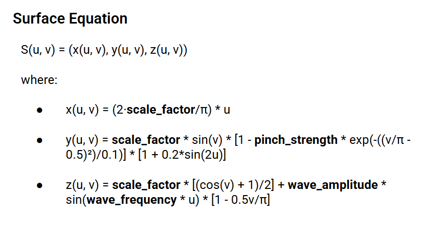
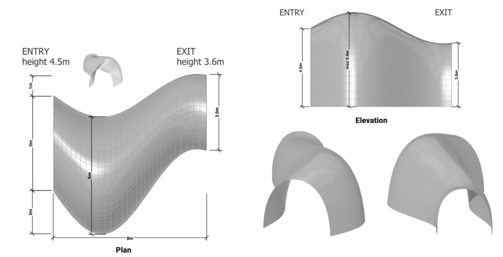
The geometry of the pavilion originates from a parametric surface equation.
This equation allowed to control scale, curvature, pinching, and wave deformation in a continuous way.
By adjusting parameters such as scale factor, pinch strength, and wave amplitude, multiple design variations were explored.
These variations were evaluated, allowing to study spatial proportions and openings.
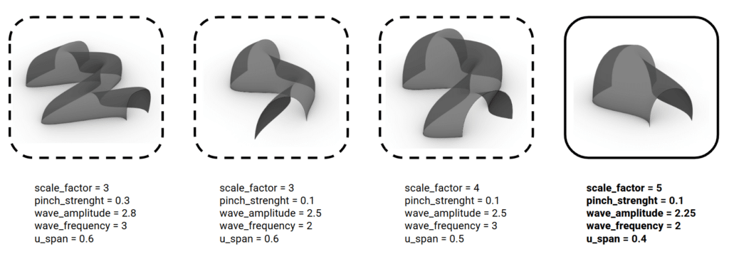
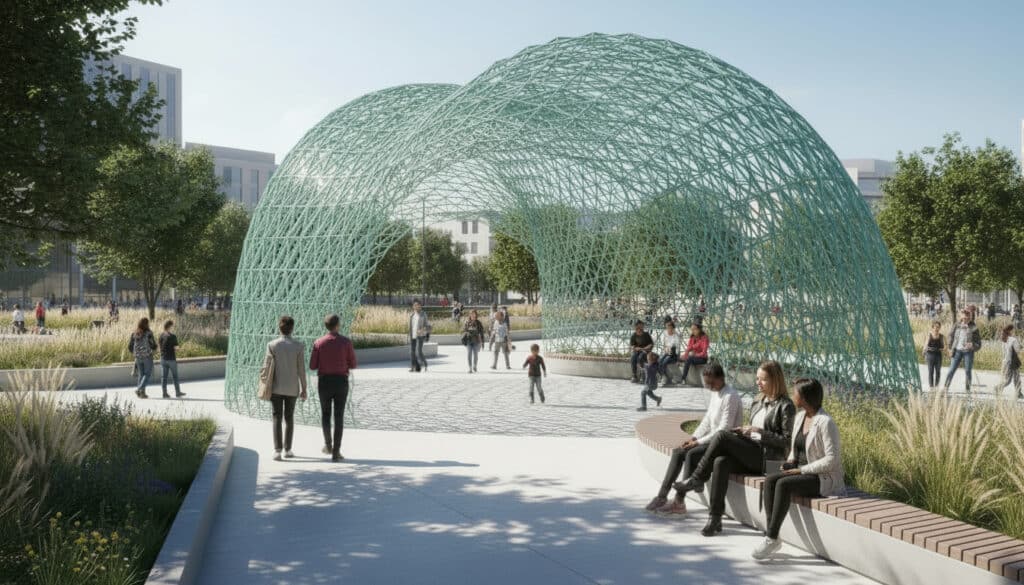
The chosen geometry balances formal expression and structural clarity, while remaining compatible with discretization into a lattice system. This structure also fits in the prescribed dimensions of the assignment (8x8x6m)
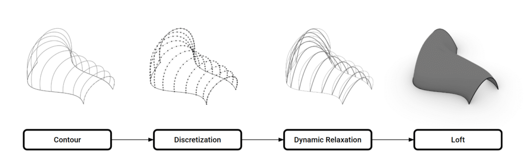
To improve structural performance, the surface geometry was further reshaped by catenary curves.
Shell Analysis
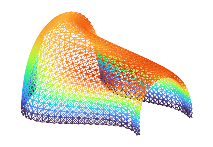
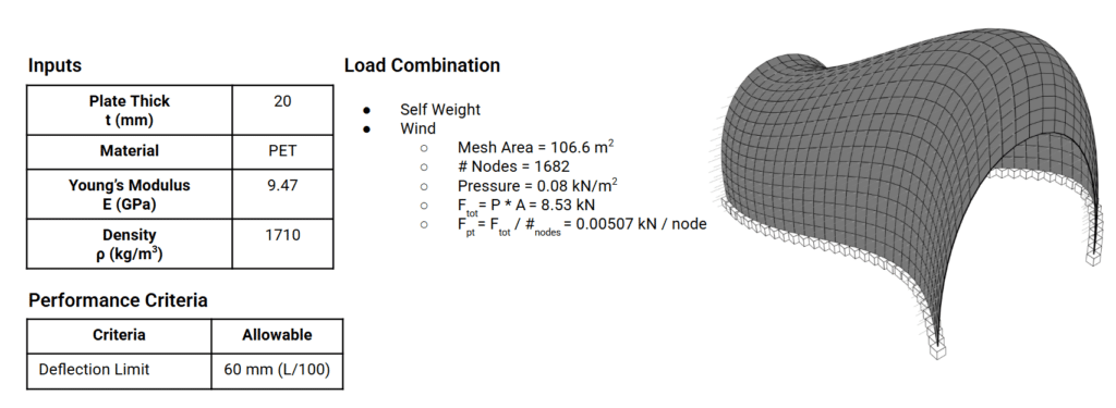
Before developing the lattice structure, the system was first analyzed as a shell. Although the mass was higher than that of the lattice configuration, the shell analysis provided valuable insights that were later used to further optimize the lattice structure.
Shell Option 01 is the original mesh and Shell Option 02 is a mesh formed from the catenary curves. In the second option, the von Mises stress was reduced at the expense of a slight increase in deflection.

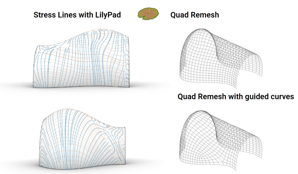
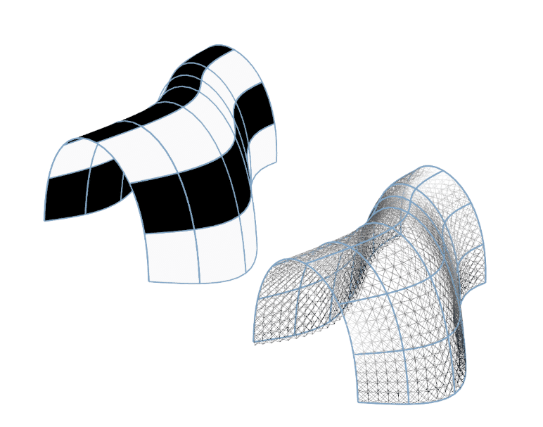
Lilypad was used to display the principal stress lines with the hope to refine the mesh further per these curves.
Lattice Structure Analysis
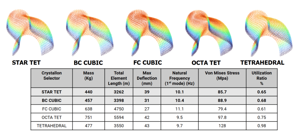
The design process then transitioned to a lattice structure. Self-weight and wind loads were applied to an initial configuration using Ø10 mm solid beam elements made from recycled reinforced glass material.

The structure was analyzed using different Crystallon beam selections. In the first run, Alpaca self-weight component was used for loading, resulting in a maximum deflection in the Z direction of nearly 40 mm for the Start Tet scenario. The stress levels remained within allowable limits, with a utilization of approximately 0.65.
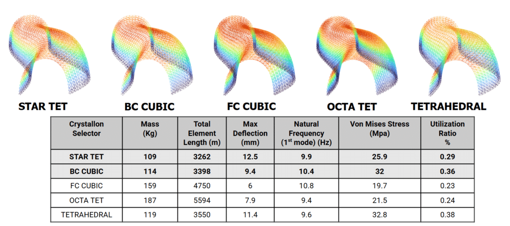
A hand calculation was then carried out to determine the self-weight reaction in the Z direction and the total shear force from wind in the Y direction, revealing a mismatch between the calculated and simulated forces. This indicated that the applied self-weight was overestimated. As a result, the Alpaca self-weight component was replaced with the total self-weight of the structure, applied as point loads at all lattice nodes. With this modified self-weight approach, the total reactions in the Z direction were verified in Alpaca, showing good agreement with the hand calculations. The same process was followed for the wind and the total shear from the wind which also agreed with the hand calculated value.

By reapplying the self-weight in a different manner, the lattice structure was found to perform significantly better. This improved performance made it possible to further reduce the beam diameter while maintaining acceptable structural behavior.

With the self-weight applied as vertical point loads, the various lattice configurations from the Crystallon selections were re-evaluated for Ø5mm beam elements . The StarTet and BC Cubic configurations demonstrated strong structural performance while requiring the fewest total beam elements, a factor that is beneficial for 3D printing and fabrication.
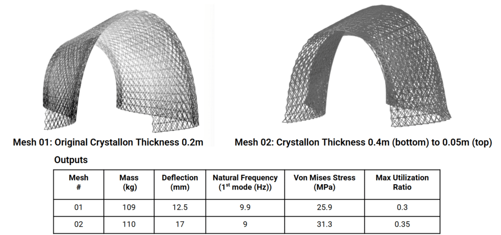
Further optimization of the lattice structure was explored by varying the offset thickness. In Mesh #01, a uniform thickness of 0.2 m was used, while in Mesh #02 the thickness varied from 0.4 m at the base to 0.05 m at the top. This approach was guided by the shell analysis, and the resulting structural performance was found to be comparable between the two cases. Additional refinement would be required to achieve further performance improvements.
Freeform 3D Printing Exploration
https://branchtechnology.com/approach/#process
- Allows 3D-printed fiber- reinforced polymers to solidify in free space
- Removes geometric and material limitations of standard fused deposition modeling (FDM)
- Uses less material than FMD printing
- Parts can we larger than the printer
- Prefabrication off-site
- Finished component assembled on-site
The pavilion is designed for freeform robotic 3D printing potentially using a KUKA 6-axis industrial robot. Unlike conventional FDM printing, robotic extrusion allows material to be deposited in free space, removing geometric constraints and enabling large-scale fabrication.
The total length of lattice elements is approximately 3262 meters. Using a conservative printing speed of 20 millimeters per second, the pure extrusion time is about 45 hours. To accommodate robot reach and fabrication constraints, the structure is intended to be panelized and printed off-site, then assembled on site.
Conclusion
The lattice pavilion achieves:
- Structural efficiency through stress-guided design
- Material optimization through variable mesh thickness
- Fabrication feasibility through robotic freeform 3D printing