
Abstract
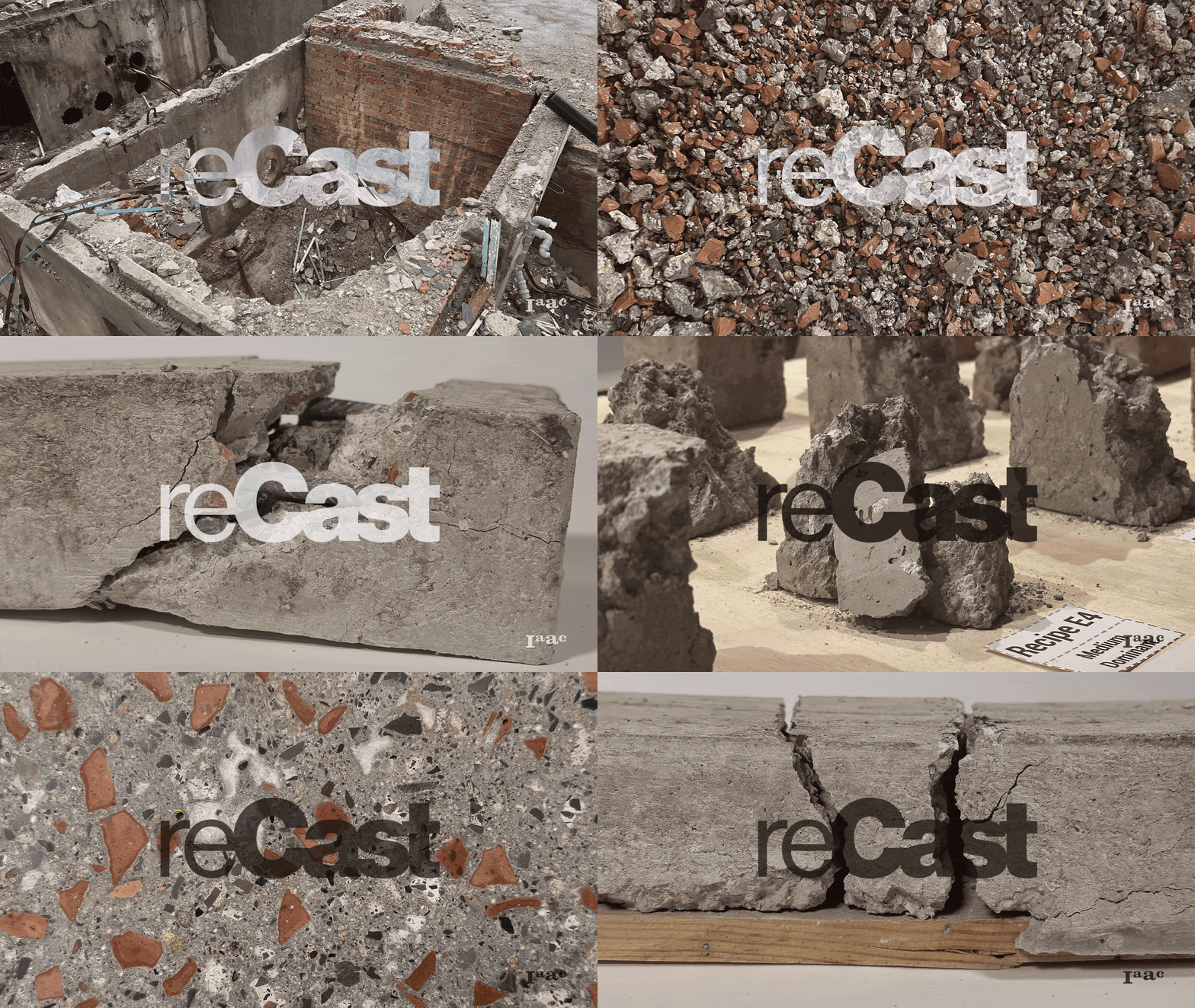
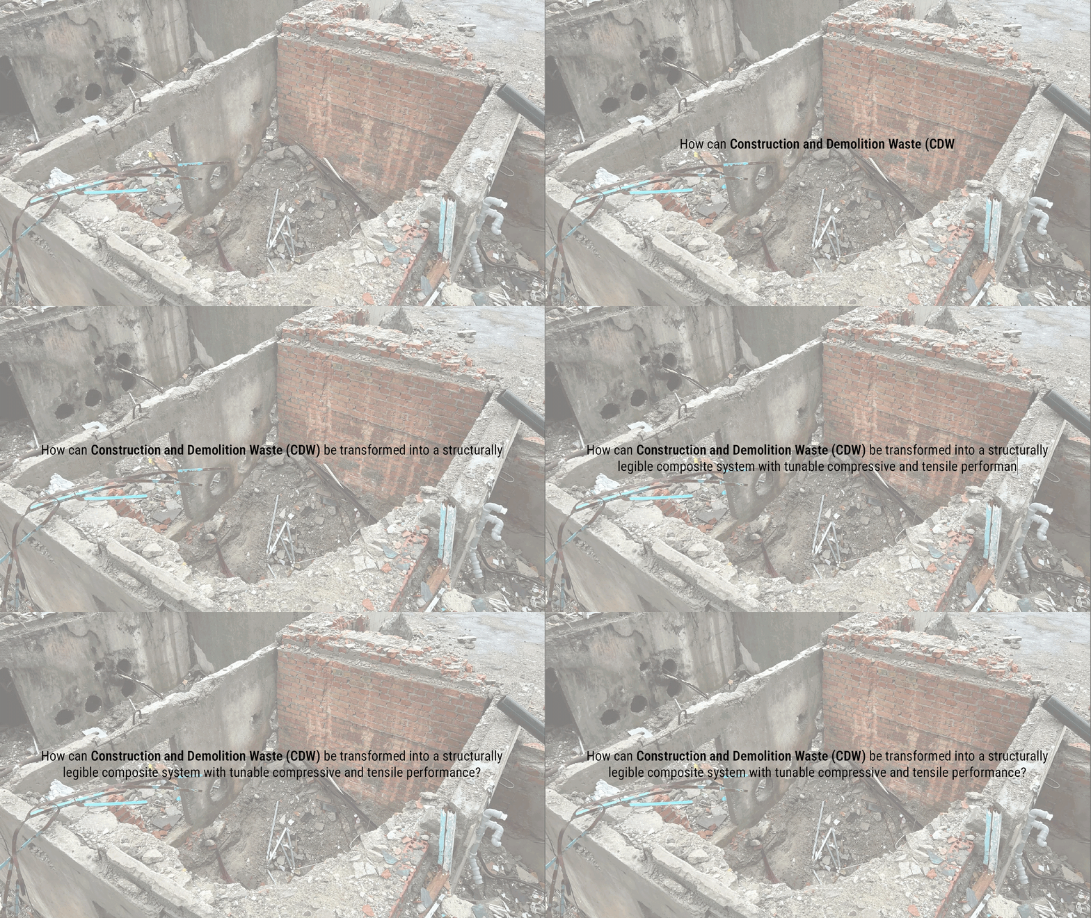
In the Anthropocene, the construction industry generates vast quantities of Construction and Demolition Waste (CDW), positioning cities as latent material reservoirs rather than endpoints of consumption. This research investigates CDW not as waste, but as a designed material system. Initial experiments explored rammed CDW composites, revealing strong compressive behavior but critical limitations under lateral forces and impact, leading to brittle failure. While compression performance showed promise, it remained insufficient for structural application.
Subsequent material studies introduced binders, demonstrating that controlled grading and minimal cement stabilization significantly improve cohesion and strength, though material alone could not resolve tensile weakness. This shifted the research toward spanning systems, integrating tensile members to compensate for material limitations. Experiments with natural fibers and reclaimed steel informed the transition to hybrid systems, ultimately incorporating salvaged rebars from construction sites.
The project proposes a precast ribbed slab system, where geometry, reinforcement, and material grading work together to achieve structural performance. Only cement is introduced as a virgin material, while aggregates and steel are reclaimed, forming a predominantly upcycled system. Prototyping focuses on flexural behavior and assembly logic.
At an urban scale, a digital interface enables the identification, evaluation, and controlled extraction of CDW, structuring a pipeline from demolition to fabrication. The work hypothesizes a scalable system where buildings become material sources, processed, assembled, and reconstituted into new architectural elements.
The CDW Paradox
Problem Framing: Environmental and Technical Gap
Material Flow: Sankey Diagram
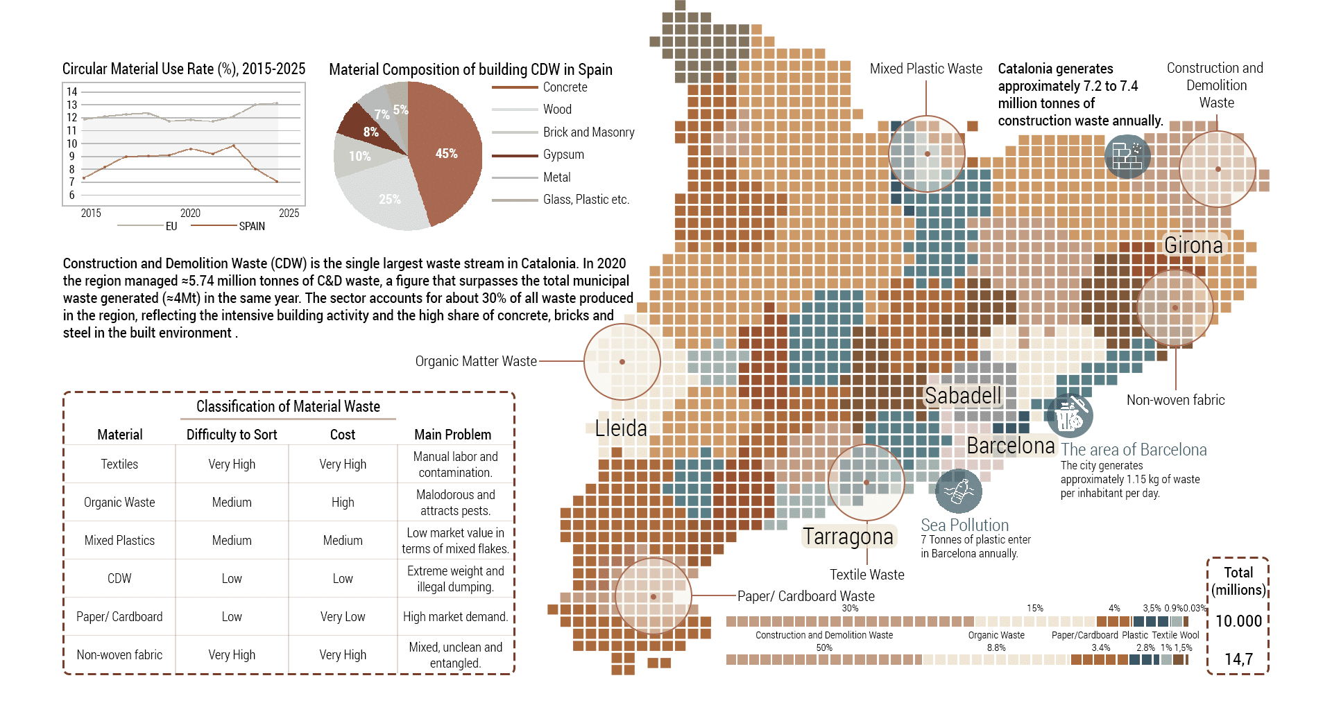
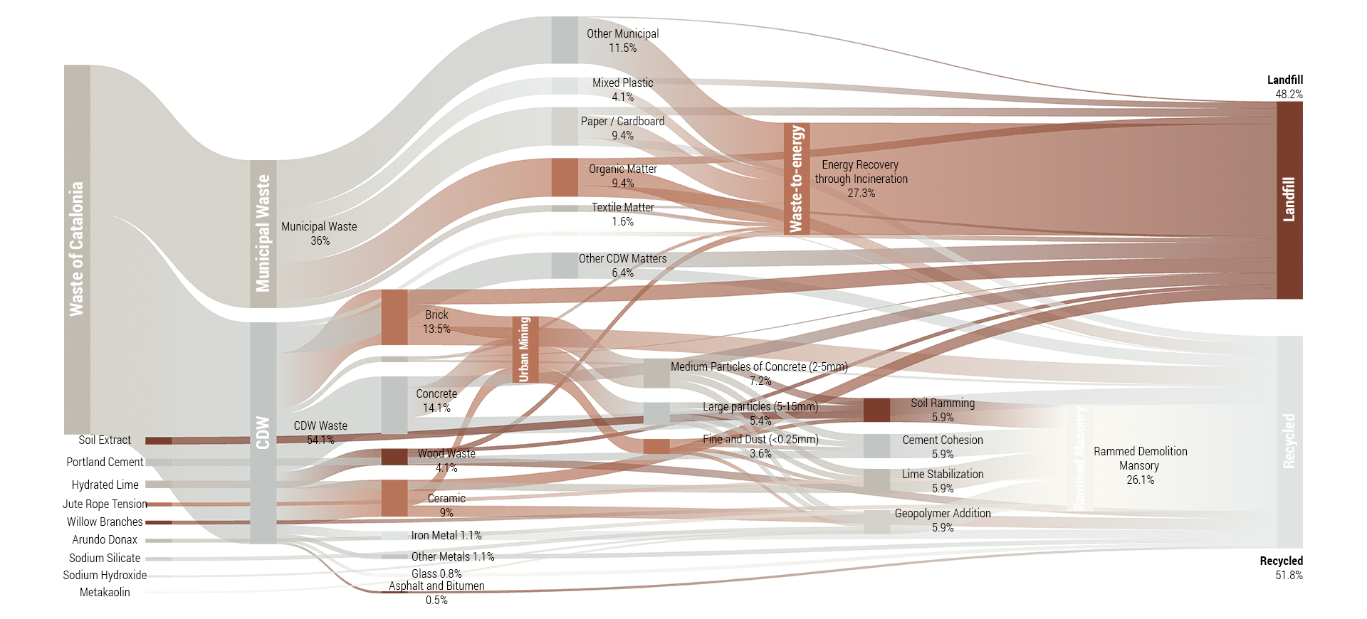
Typical CDW composition in Catalonia mirrors the European pattern: concrete ≈ 40 %, brick waste 20‑25 %, steel‑metal ≈ 10 %, glass ≈ 10 %, with additional fractions of asphalt/bitumen, gypsum/plaster and ceramic mix 10‑25 % that together complete the material balance.
These figures illustrate that Catalonia’s construction sector generates a substantial volume of material that is only partially reintegrated into the circular economy, underscoring the urgent need for more effective waste‑reduction, material‑recovery and reuse strategies.
Material Focus
CDW in Structural Research
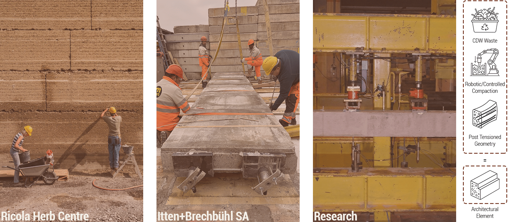
ResearchGate, Reinforced Concrete Beams with Recycled Aggregates from Demolished Concrete of a Stadium.
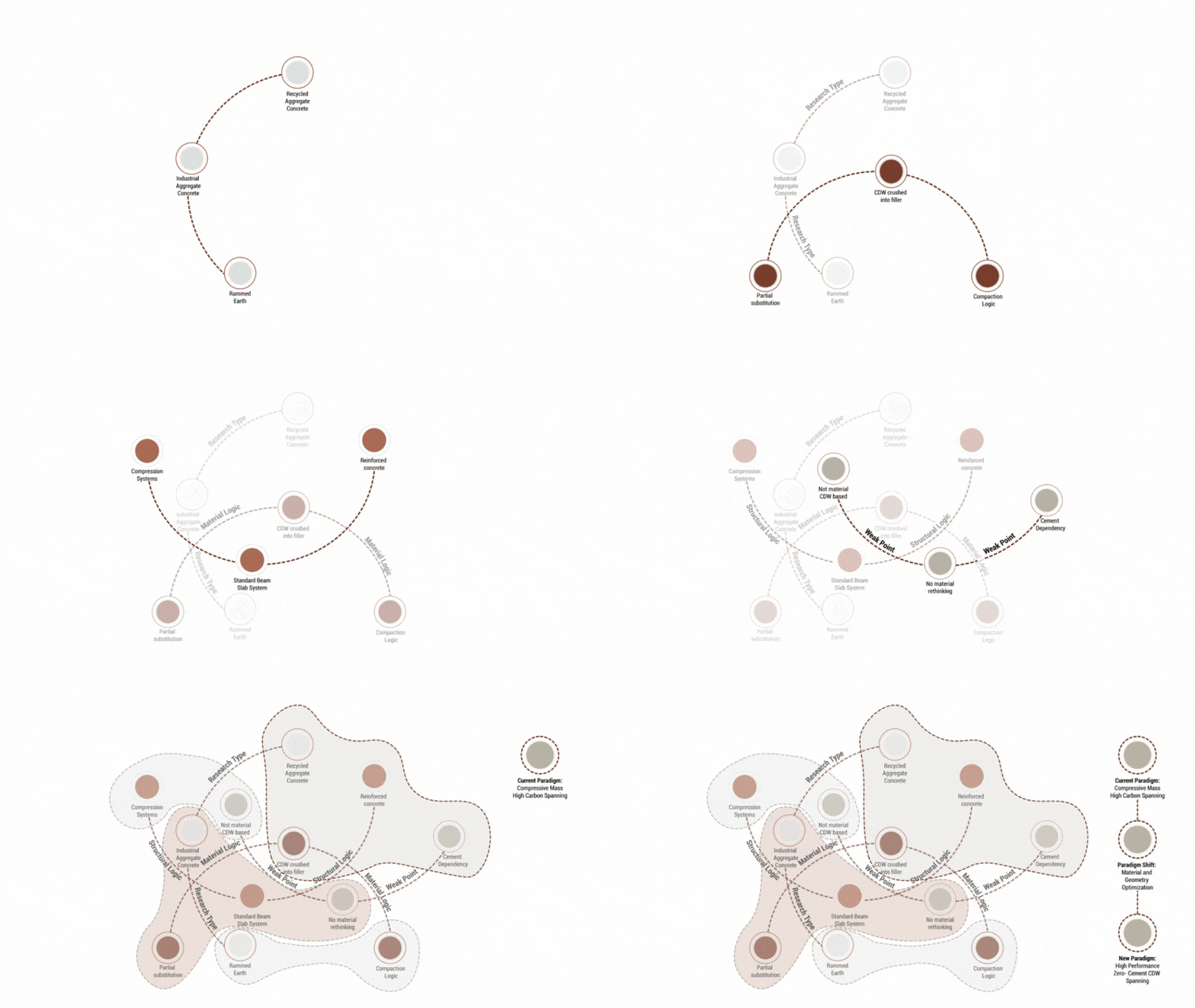
Research Gap
Redesigning Matter for a Circular Future
Urban Mining and Granular Intelligence
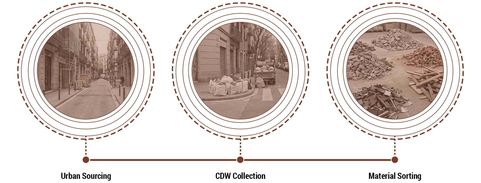
Urban Mining Workflow
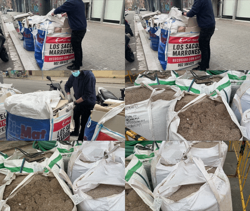
Sourcing and Collection
Material Processing
Mineral Material Classification
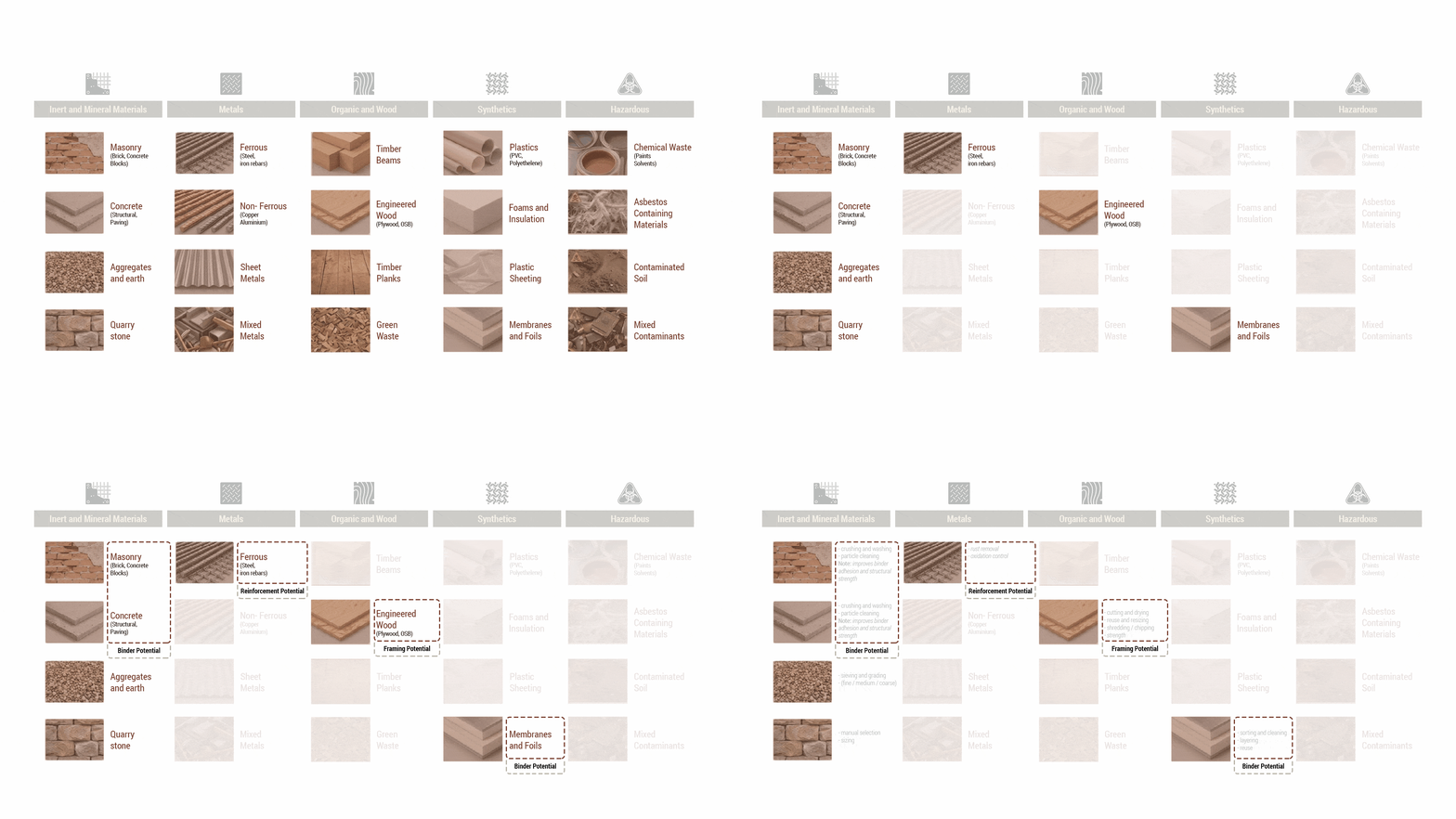
Mineral Breakdown
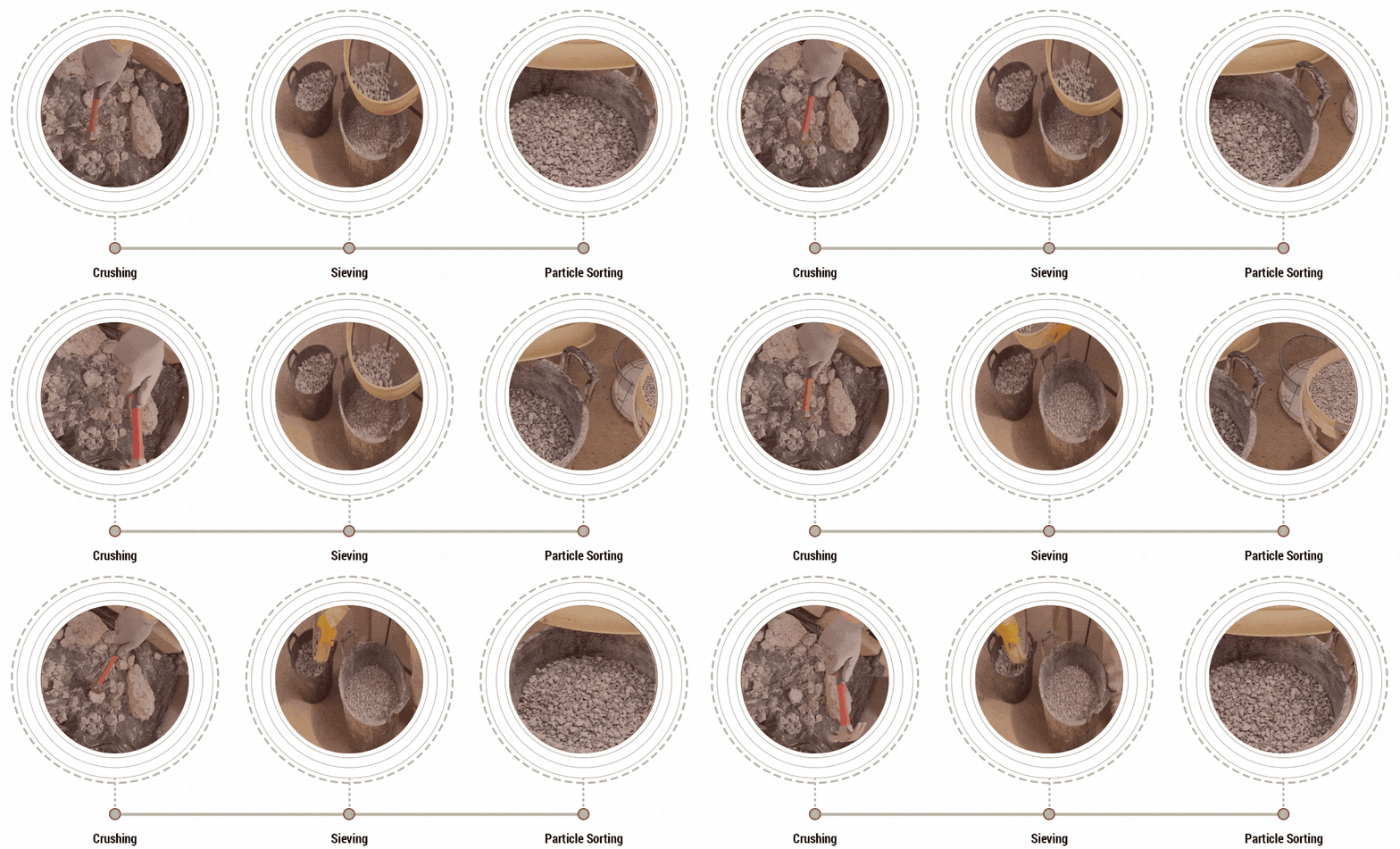
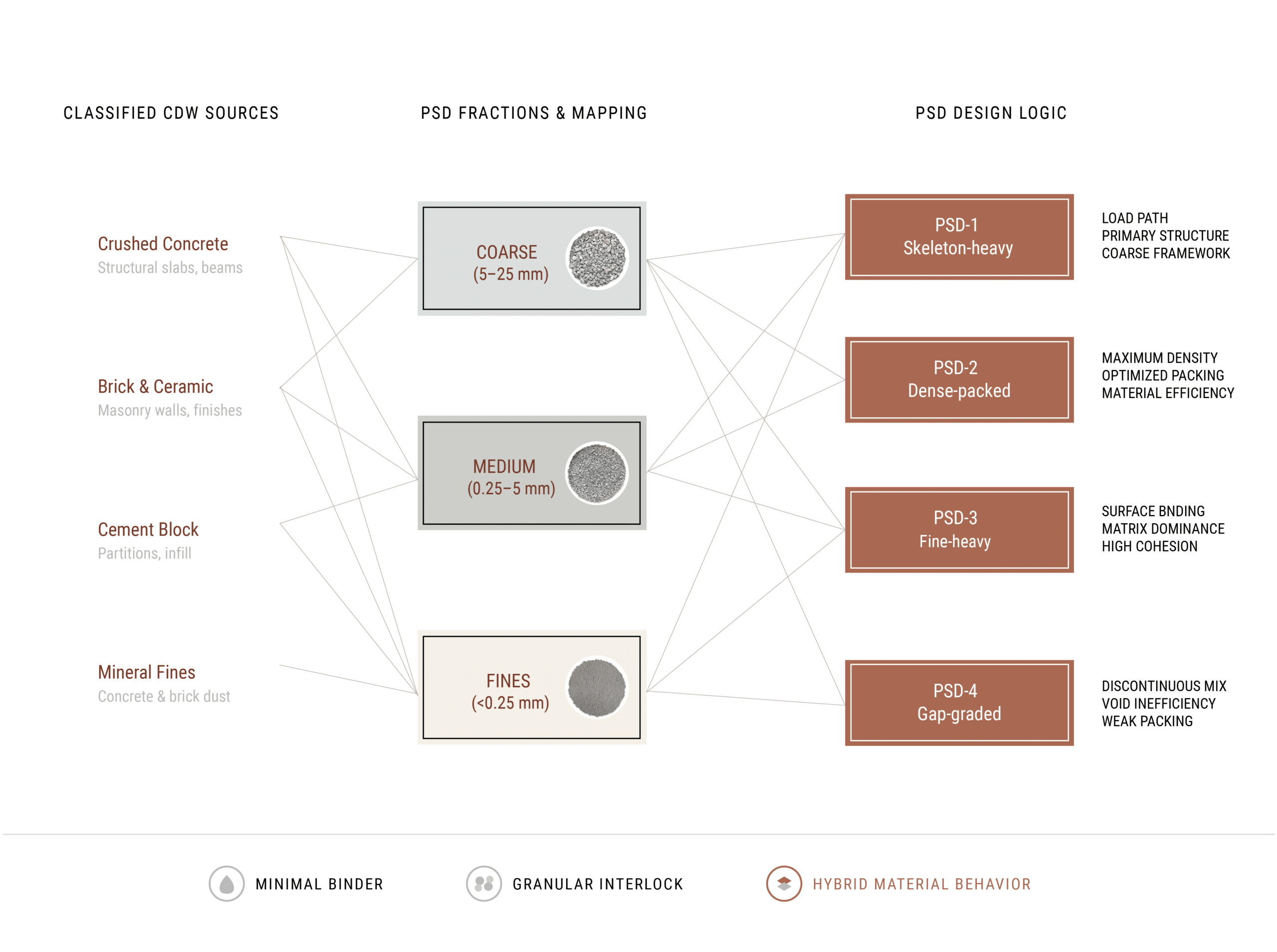
Particle Size as Design Parameter
Mineral Particle Size Catalogue
Granular Intelligence
Mohammed Al-Surf; Mosleh Al-Harthi; and Ashraf Balabel. Strength and Water Absorption of Sustainable Concrete Produced with Recycled Basaltic
Concrete Aggregates and Powder. Sustainability 13, no. 11 (2021): 6277.
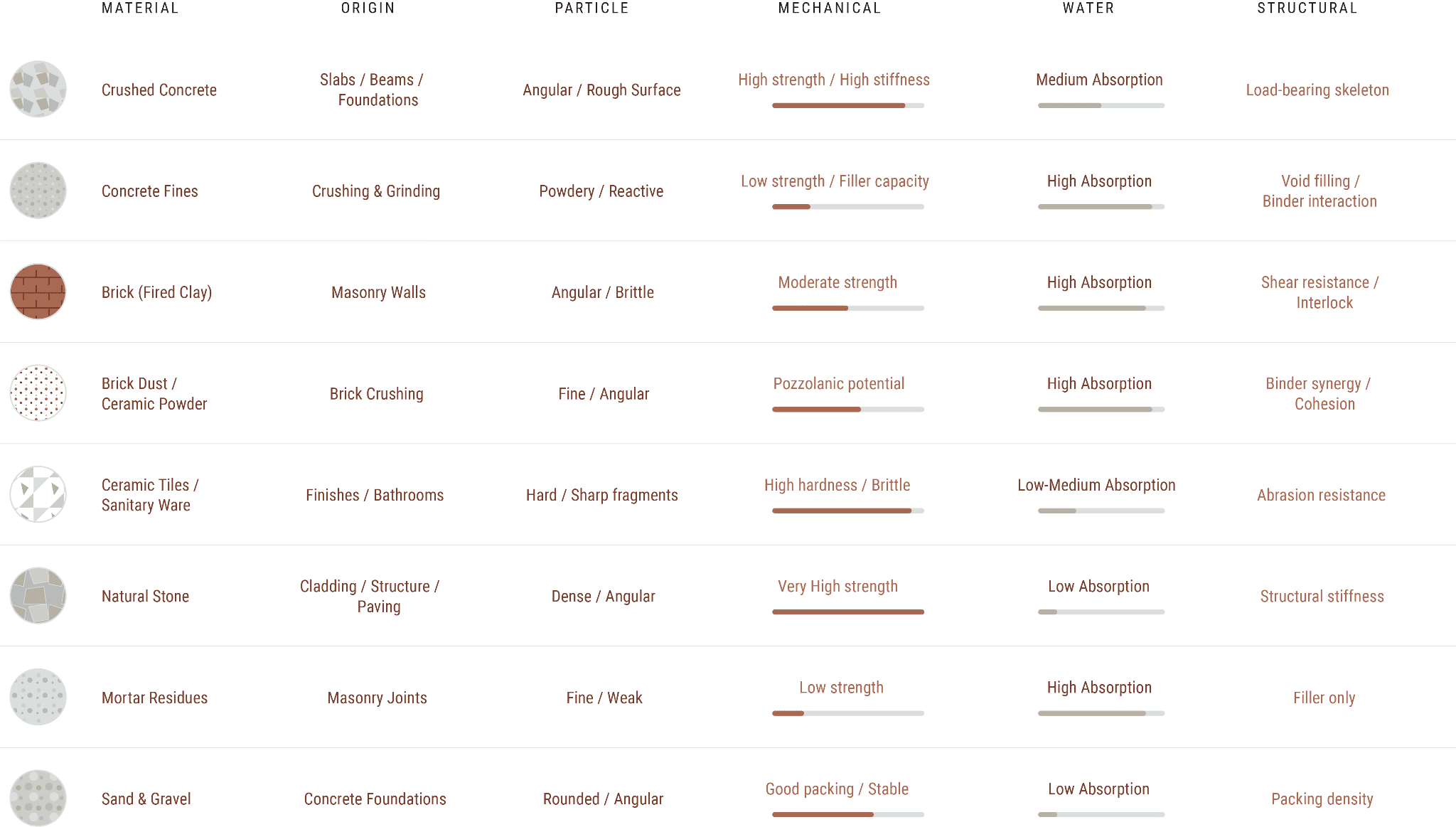
Material Property Mapping
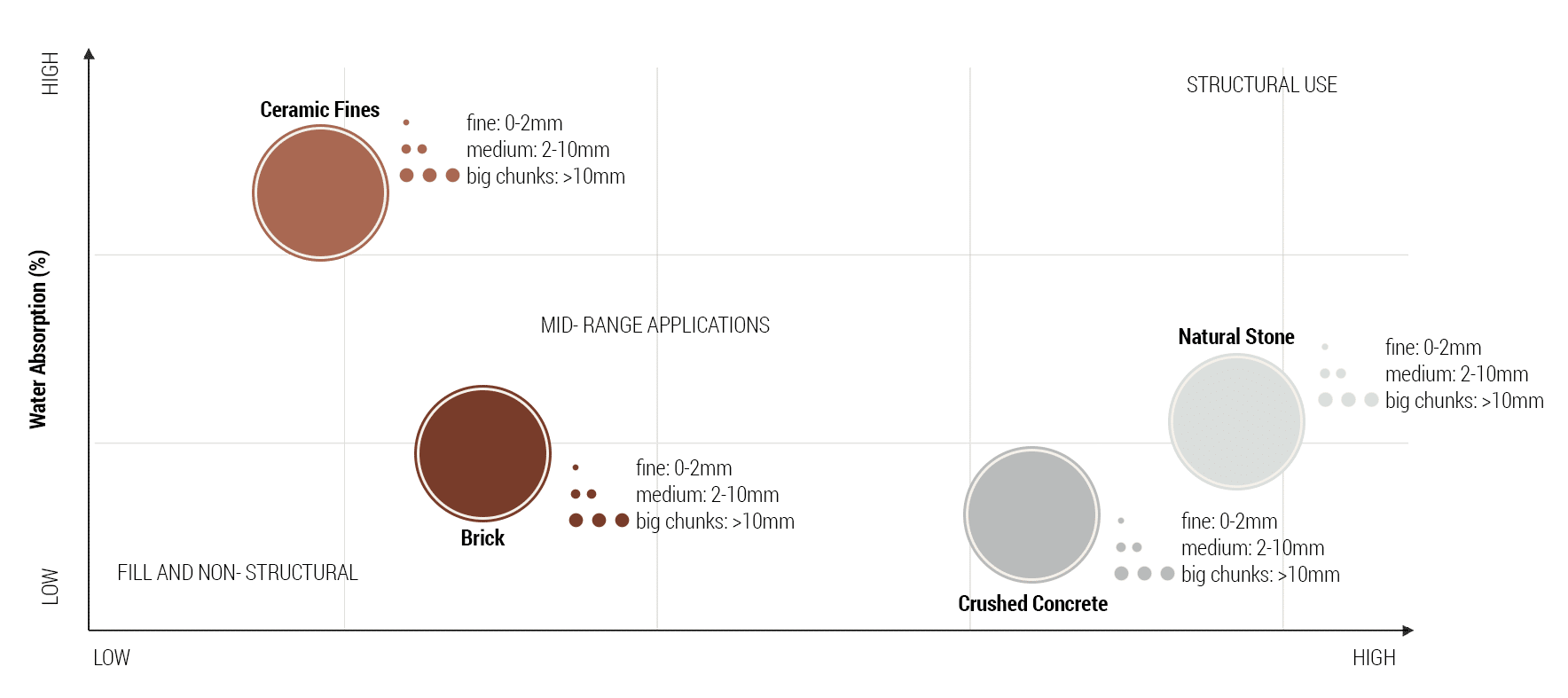
Surf; Mosleh Al-Harthi; and Ashraf Balabel. Strength and Water Absorption of Sustainable Concrete Produced with Recycled Basaltic Concrete
Aggregates and Powder. Sustainability 13, no. 11 (2021): 6277.
Material Performance and Compaction Experiments
At this stage the research transitions from the urban mining workflow to material experimentation.
Ramming as a Design Parameter
Finding Structural Integrity through Granular Density
Across these references, ranging from prefabricated blocks to in-situ manual and mechanical techniques, it is observed that variations in pressure and layering contribute to both structural integrity and architectural expression.
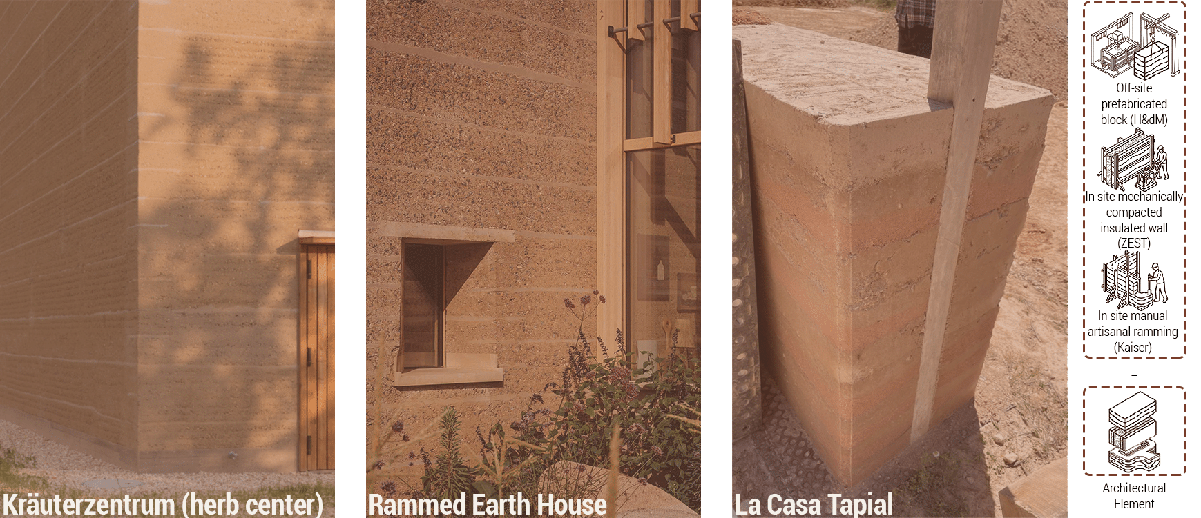
and build a rammed earth wall.
Compaction Experiments
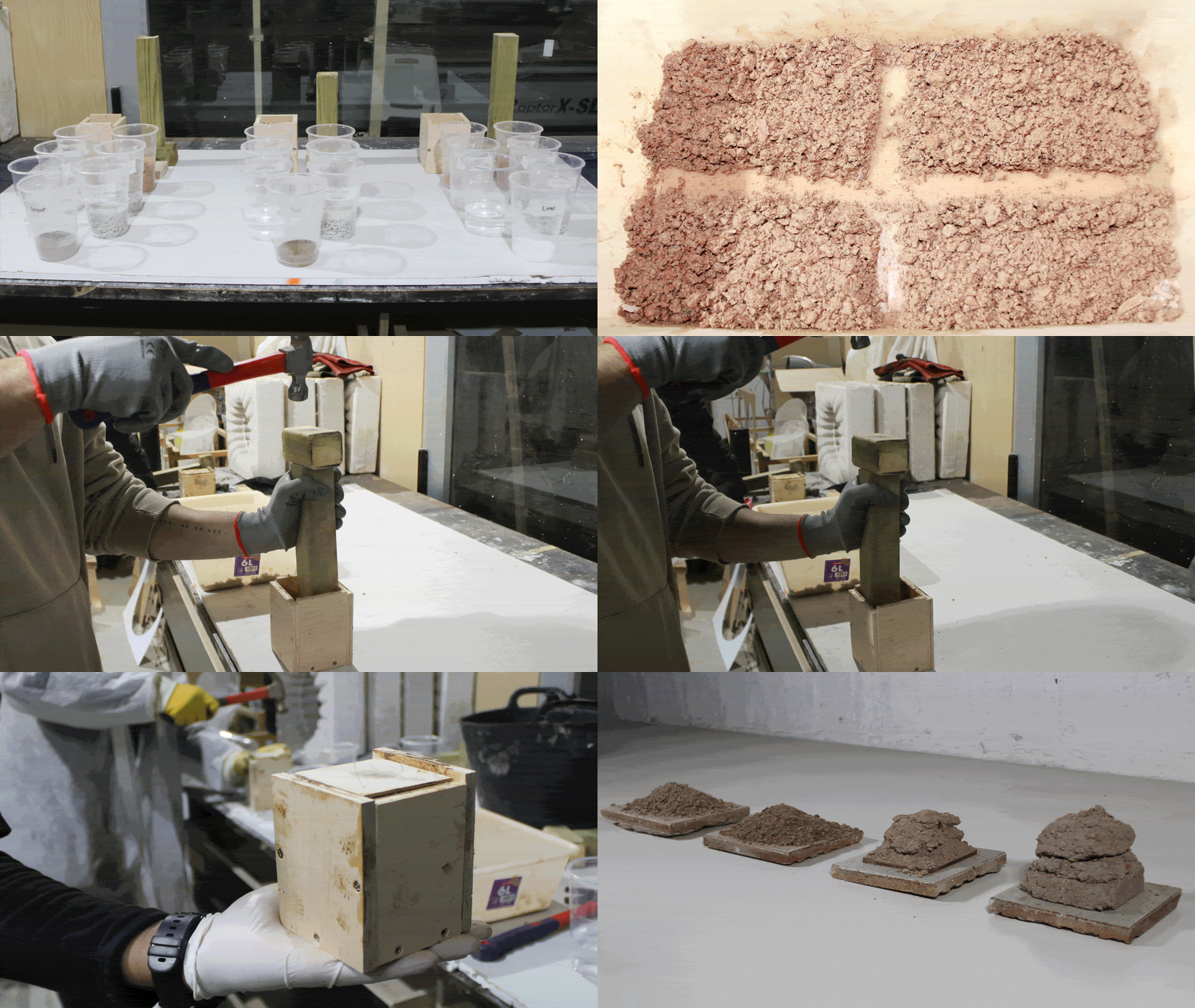
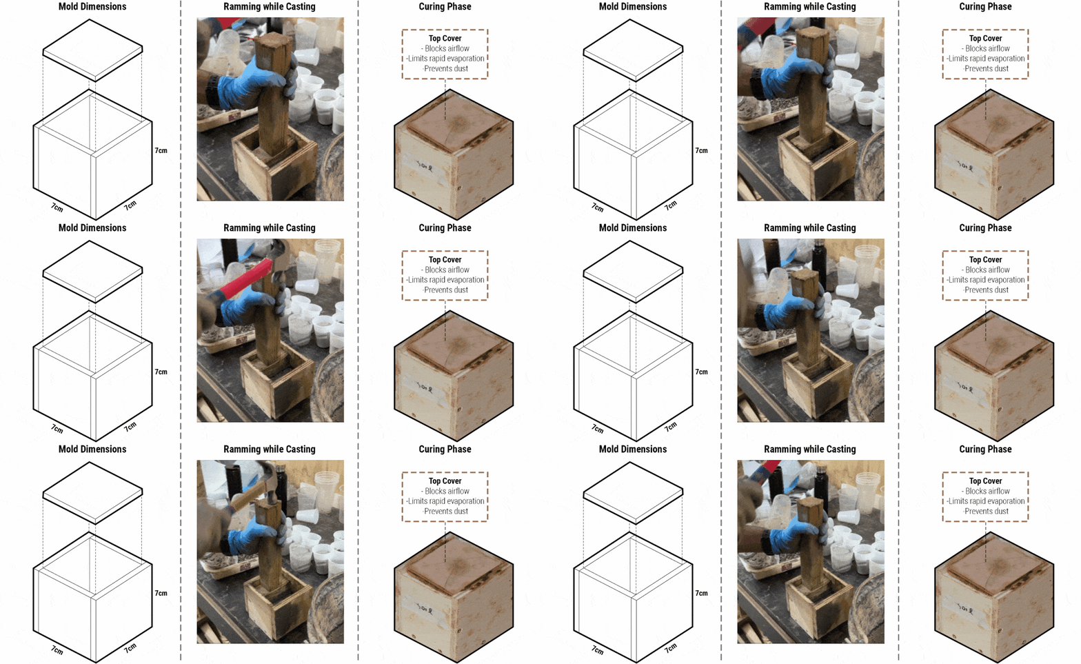
Fabrication Parameters
A 7 cm mold was used, with ramming for compaction and sealed curing to control airflow.
Formulation and Demolding
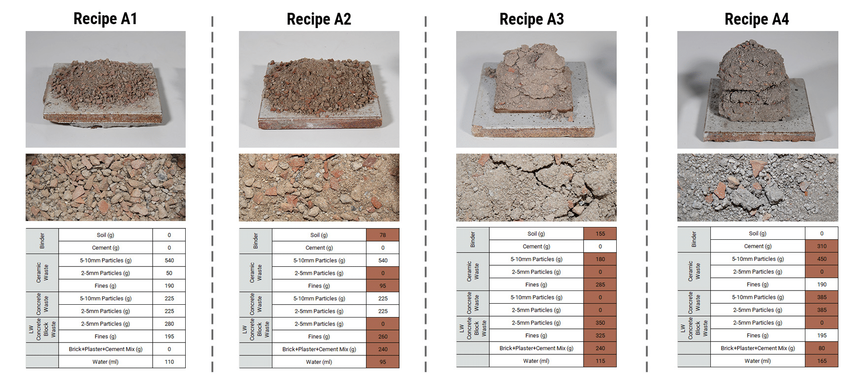
Experiment Set A Dry Ramming
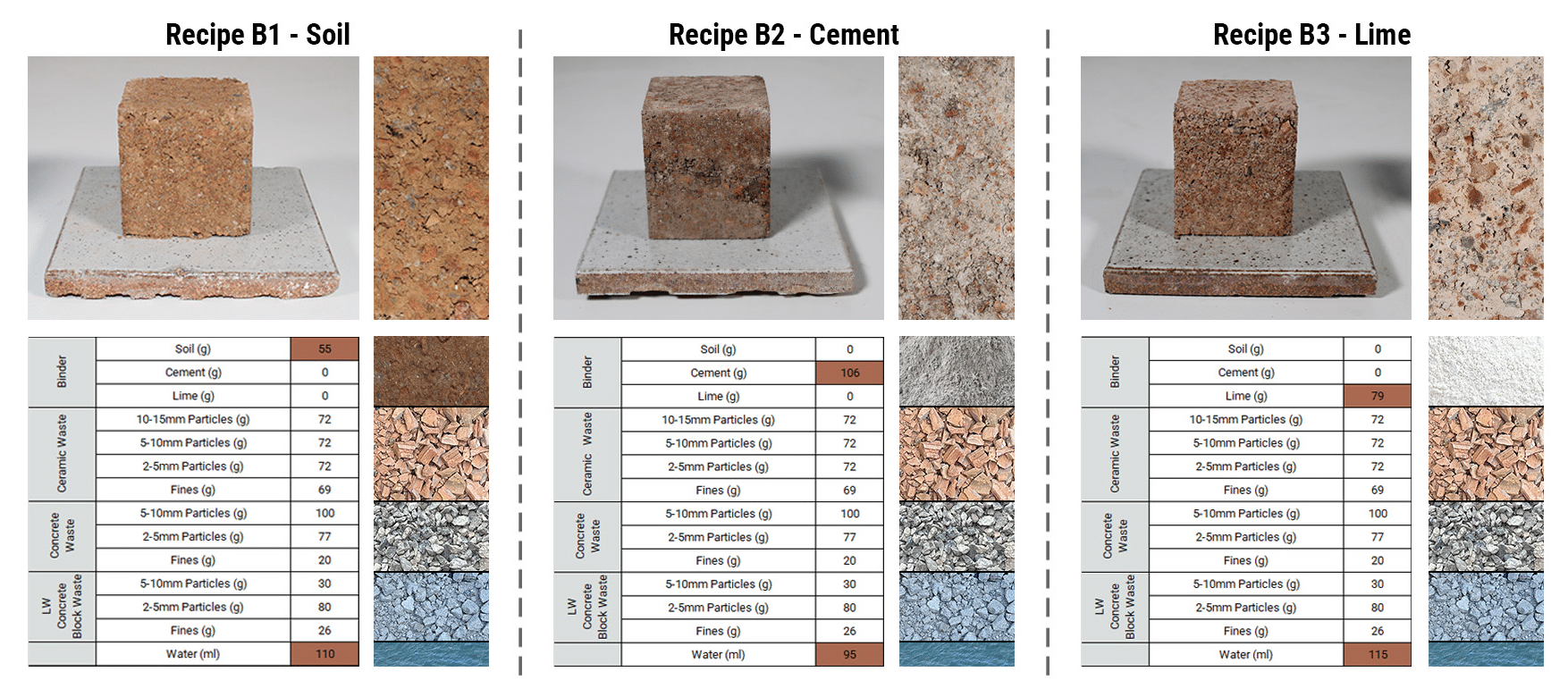
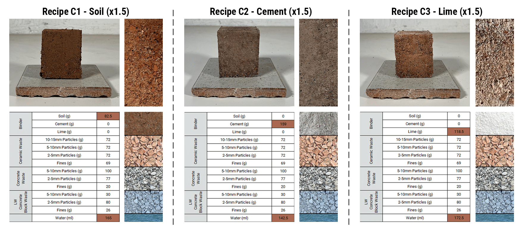
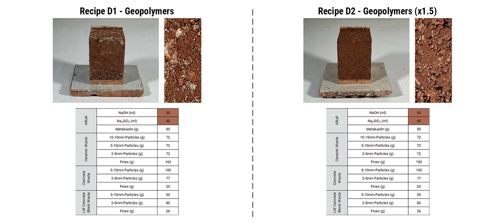
The first batch of experiments consisted of 12 different recipes, exploring a range of binders, including soil, cement, lime, and geopolymers, alongside varying particle size distributions.
Experiment Set B Binder Controlled Cohesion
Experiment Set C Phased Binder Ratios
Experiment Set D Low Carbon Mineral Binders
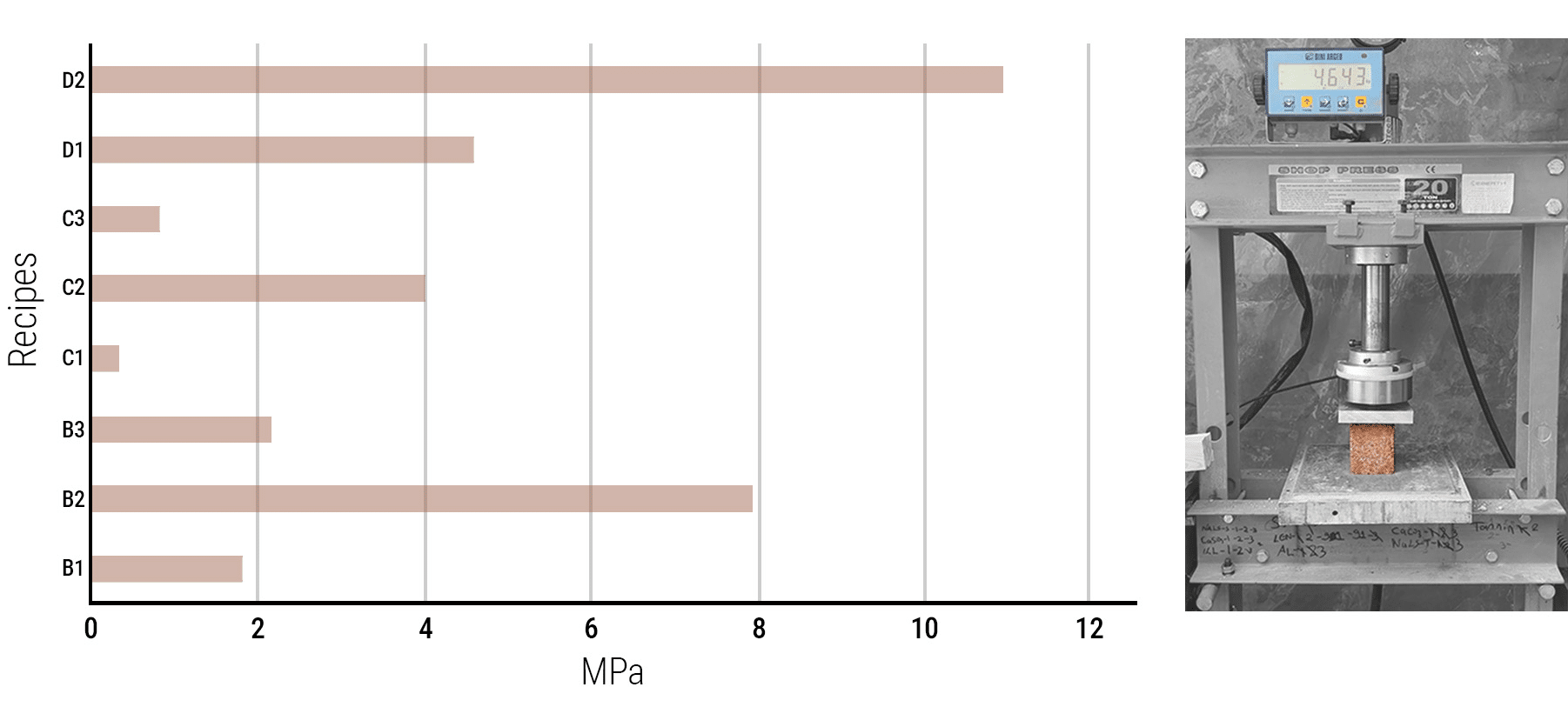
Compression Performance Tests for Experiments B, C, D
Analysis and Best Performance
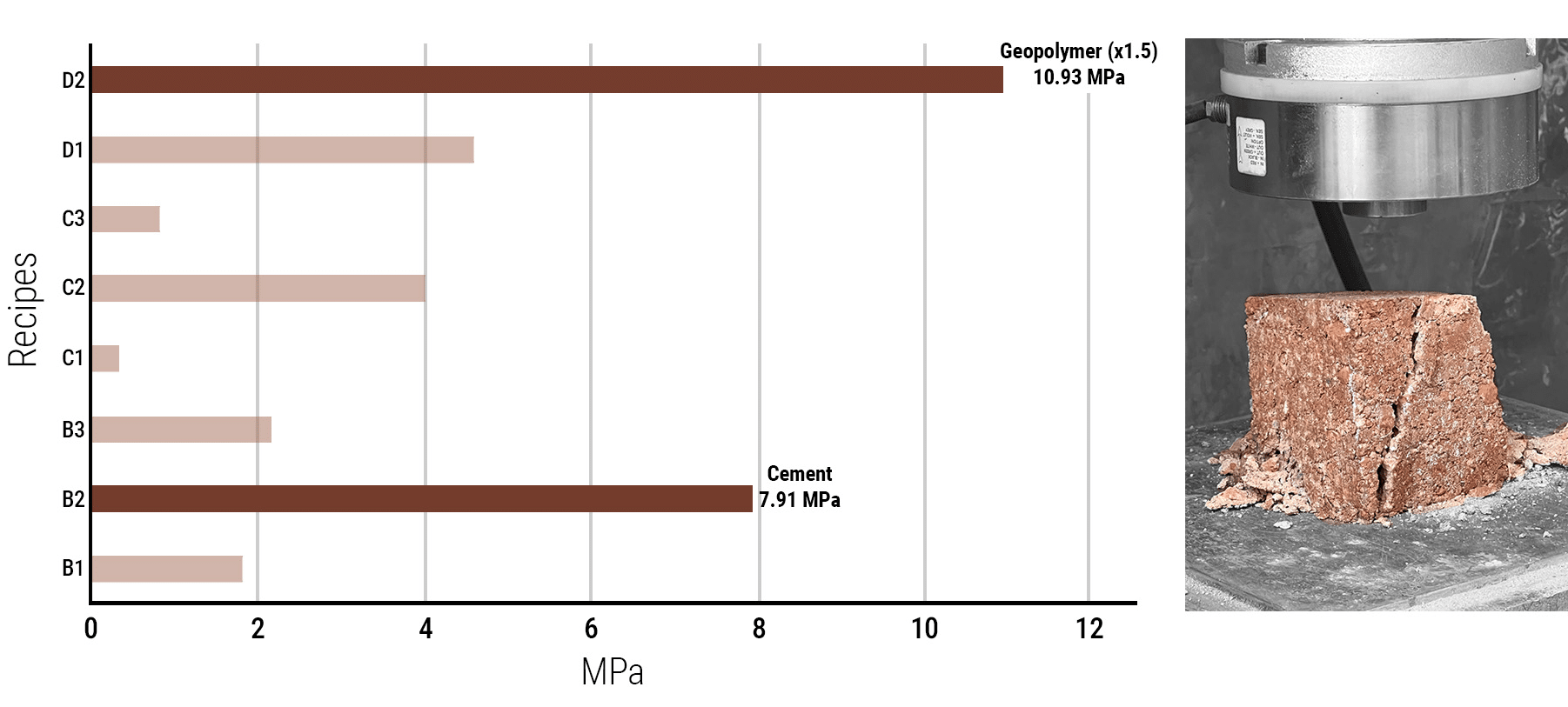
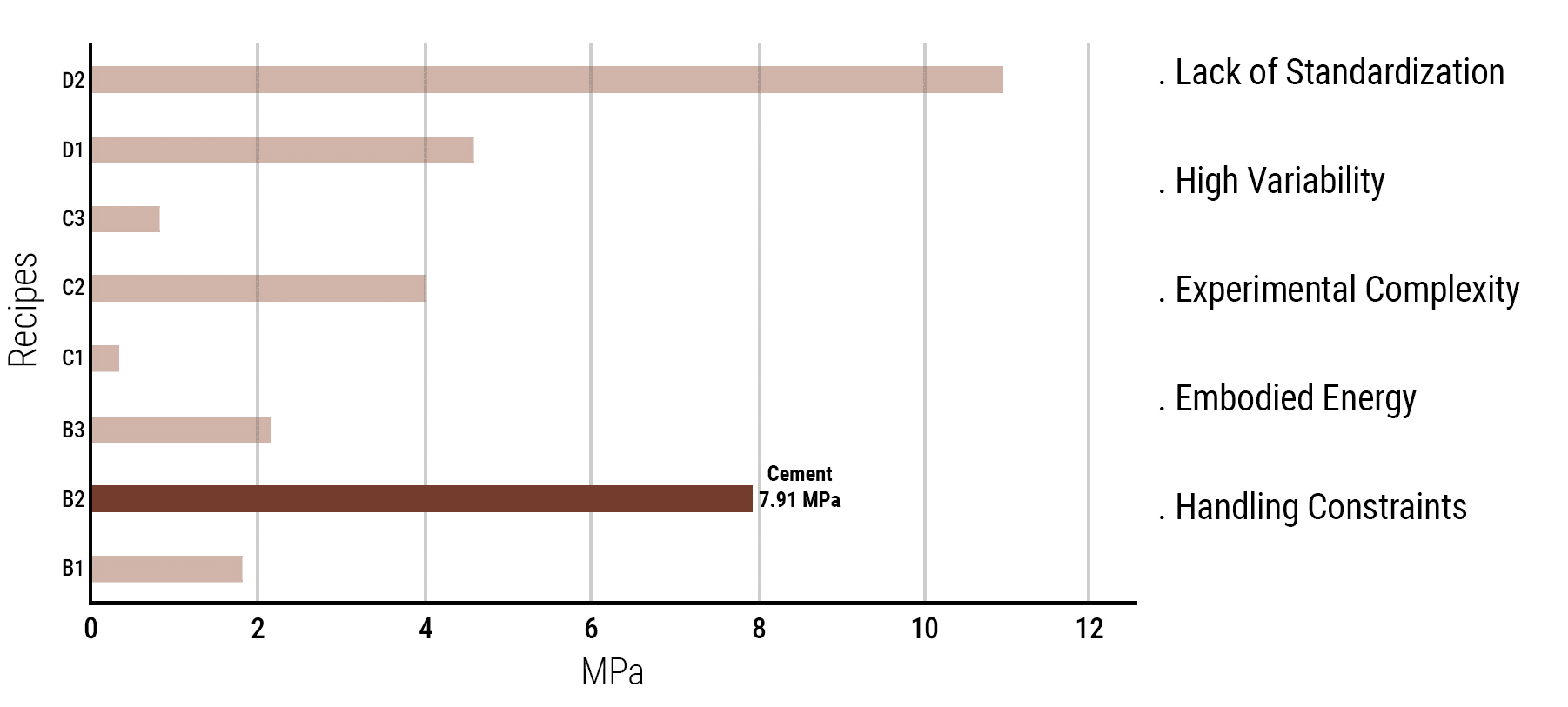
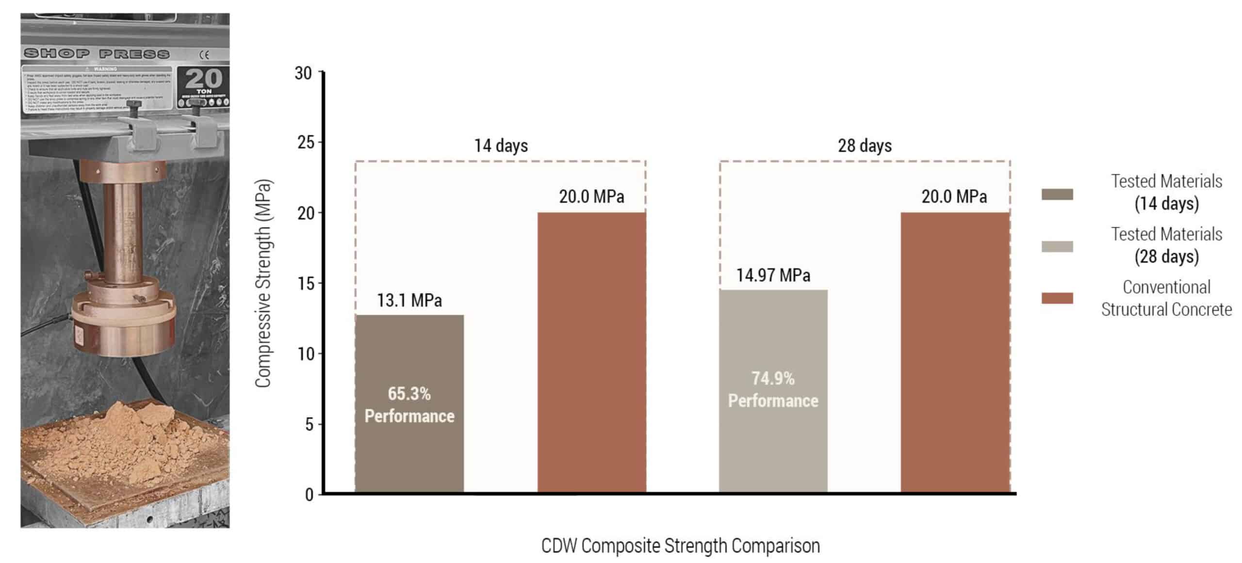
After 14 days of curing, compressive strength tests were conducted on all prototypes. The highest-performing mixes were identified as those using geopolymers and cement as binders. However, geopolymers were excluded due to their variability, lack of standardization, and complex chemistry, which made it difficult to isolate and accurately evaluate the performance of CDW materials.
Conclusion and Next Steps
Experiments A/B/C/D
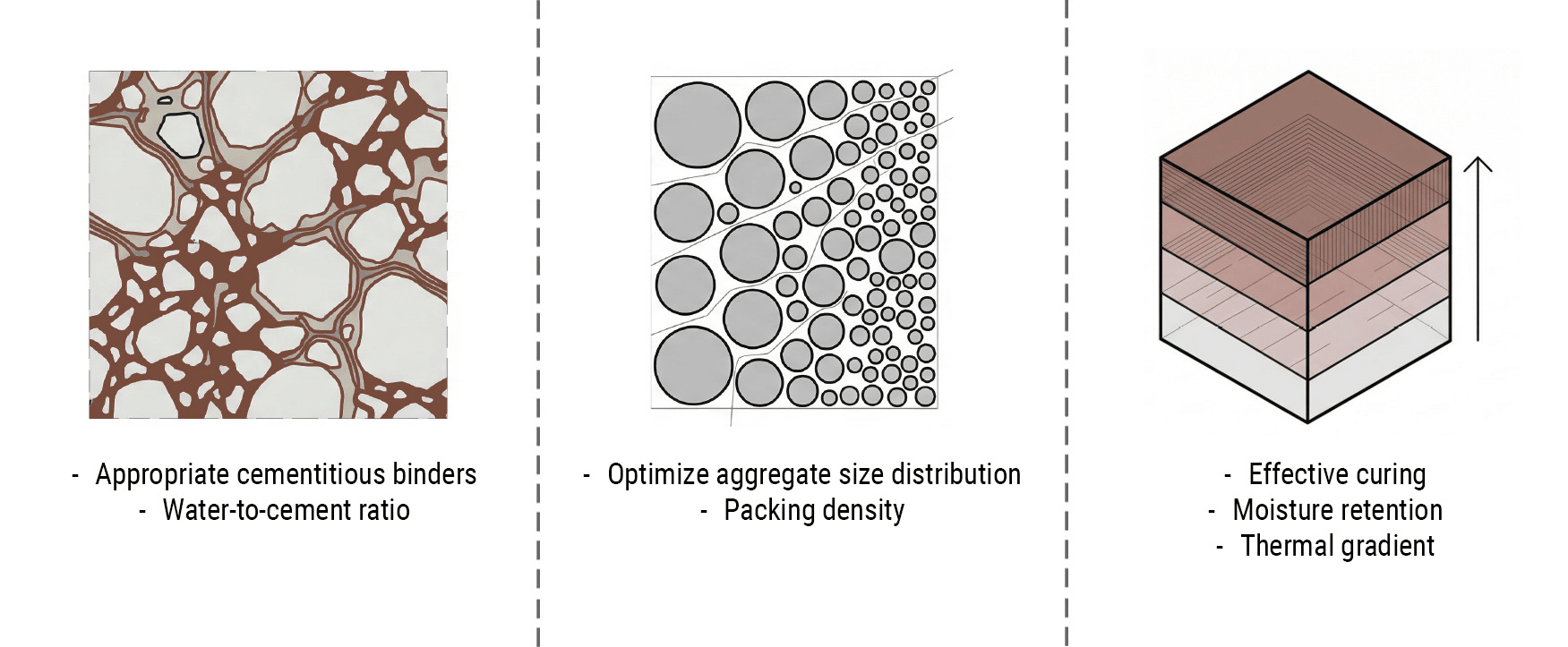
The findings established cement as the primary binder, highlighted the need for optimized particle distribution, and revealed strength loss due to moisture evaporation during curing.
Experiment Set E: Testing Aggregate Variation
Fabrication Parameters
Experiment set E focuses on testing aggregate variation in compacted construction and demolition waste elements. The same procedure was applied, 7 cm mold, with ramming for compaction and sealed curing to control airflow.
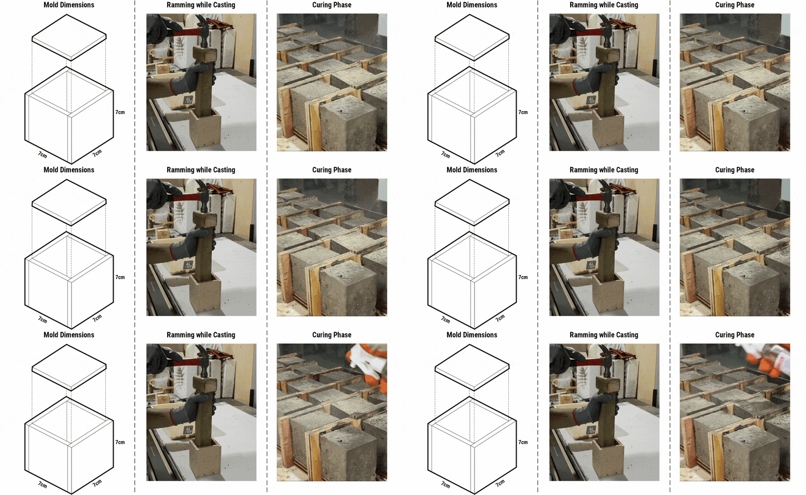
Formulation
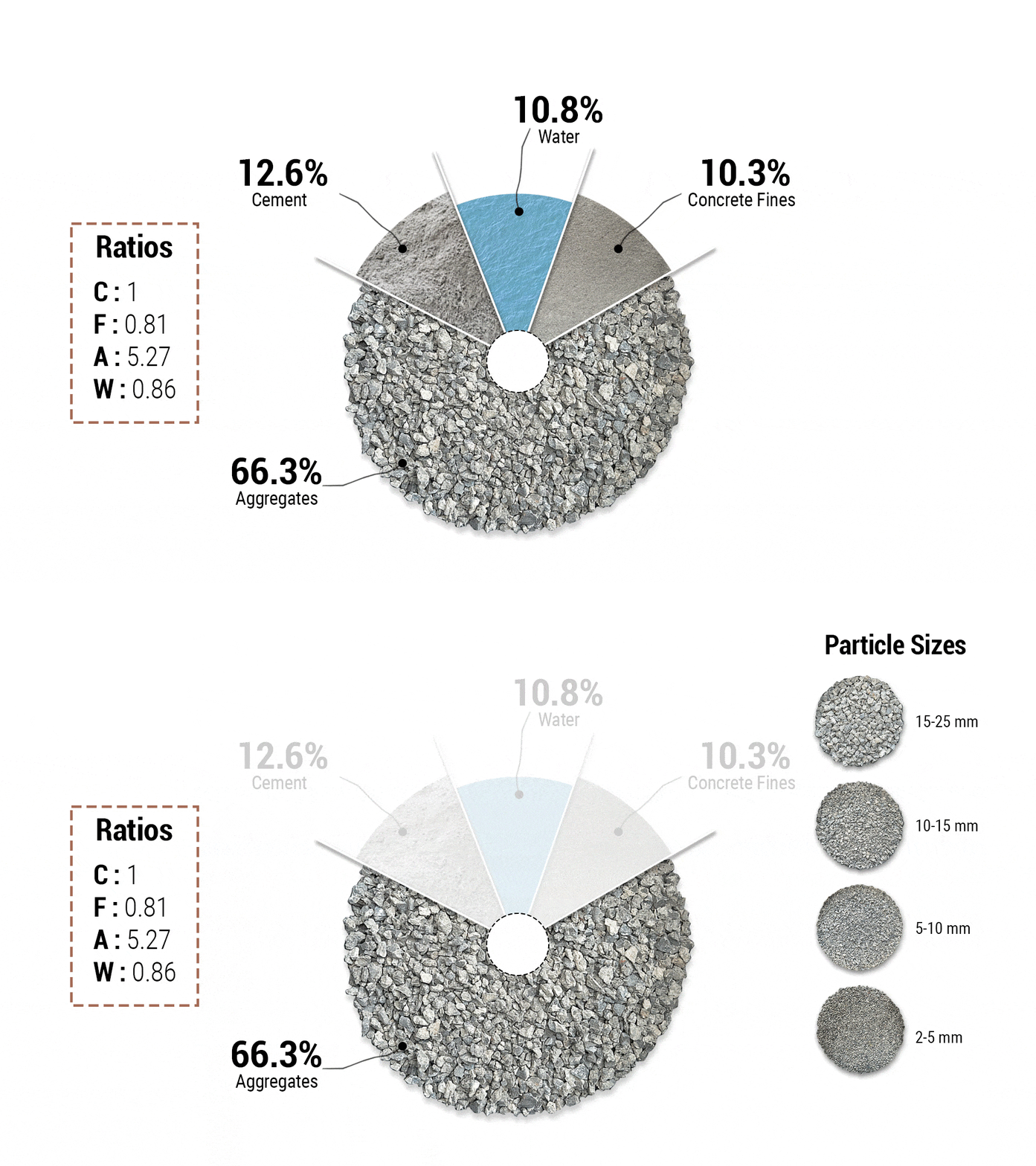
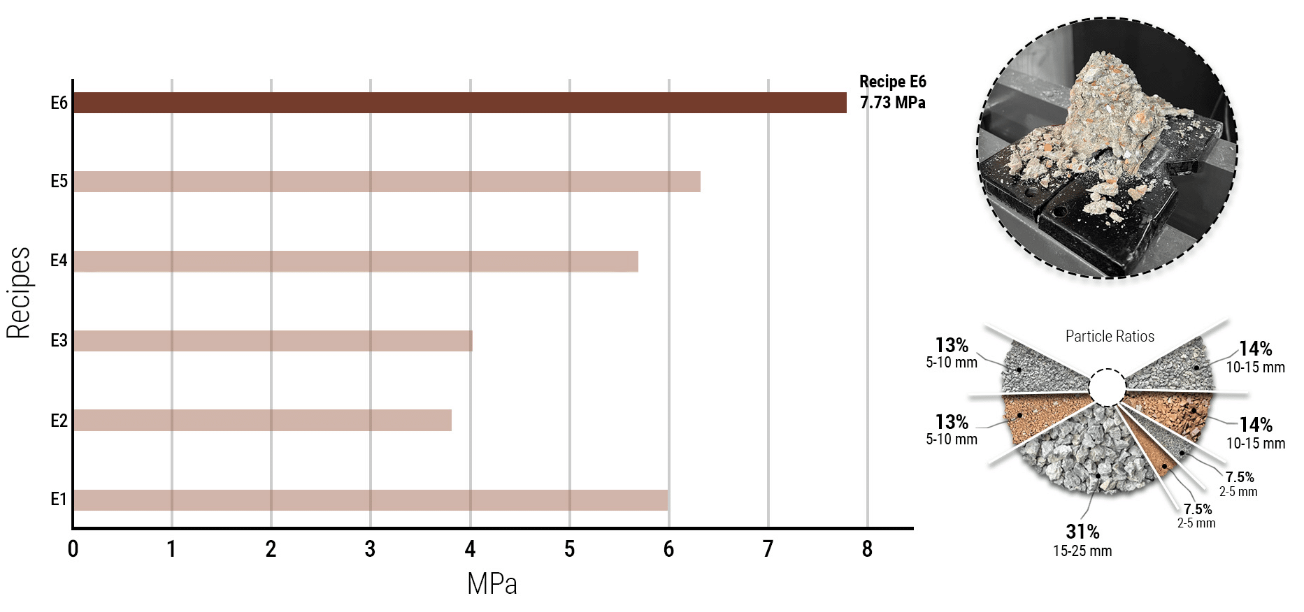
The prototype’s composition is as follows, with the corresponding ratios: cement 1, fines 0.81, aggregates 5.27, and water 0.86. The aggregates, which make up 66.3% of the mix, are distributed across four particle sizes: 15 to 25 millimeters, 10 to 15 millimeters, 5 to 10 millimeters, and 2 to 5 millimeters. This range allows us to test different packing and interlocking behaviors.
Particle Sizes and Demoulding
Analysis and Best Performance
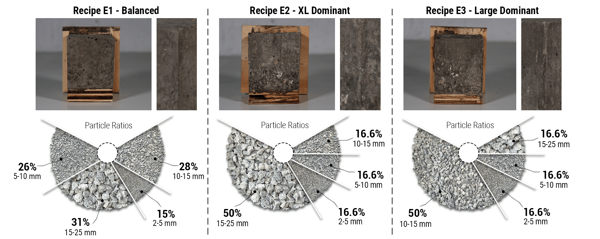
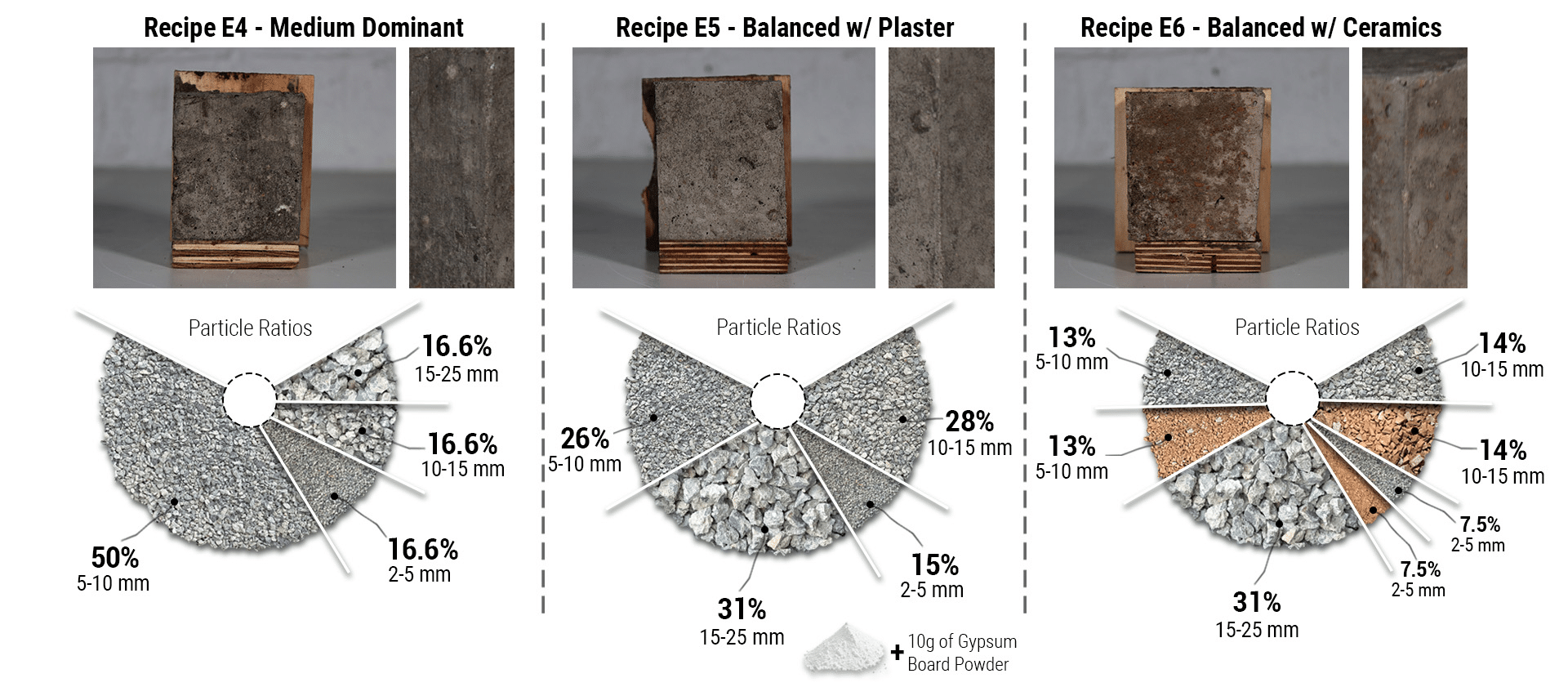
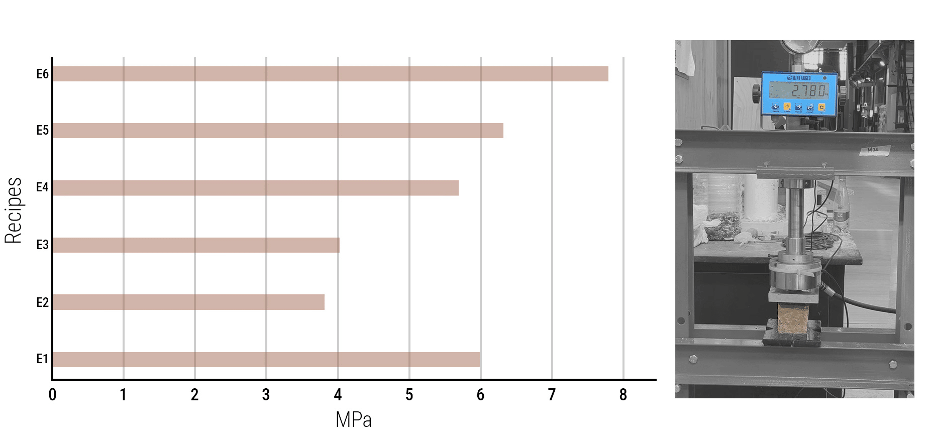
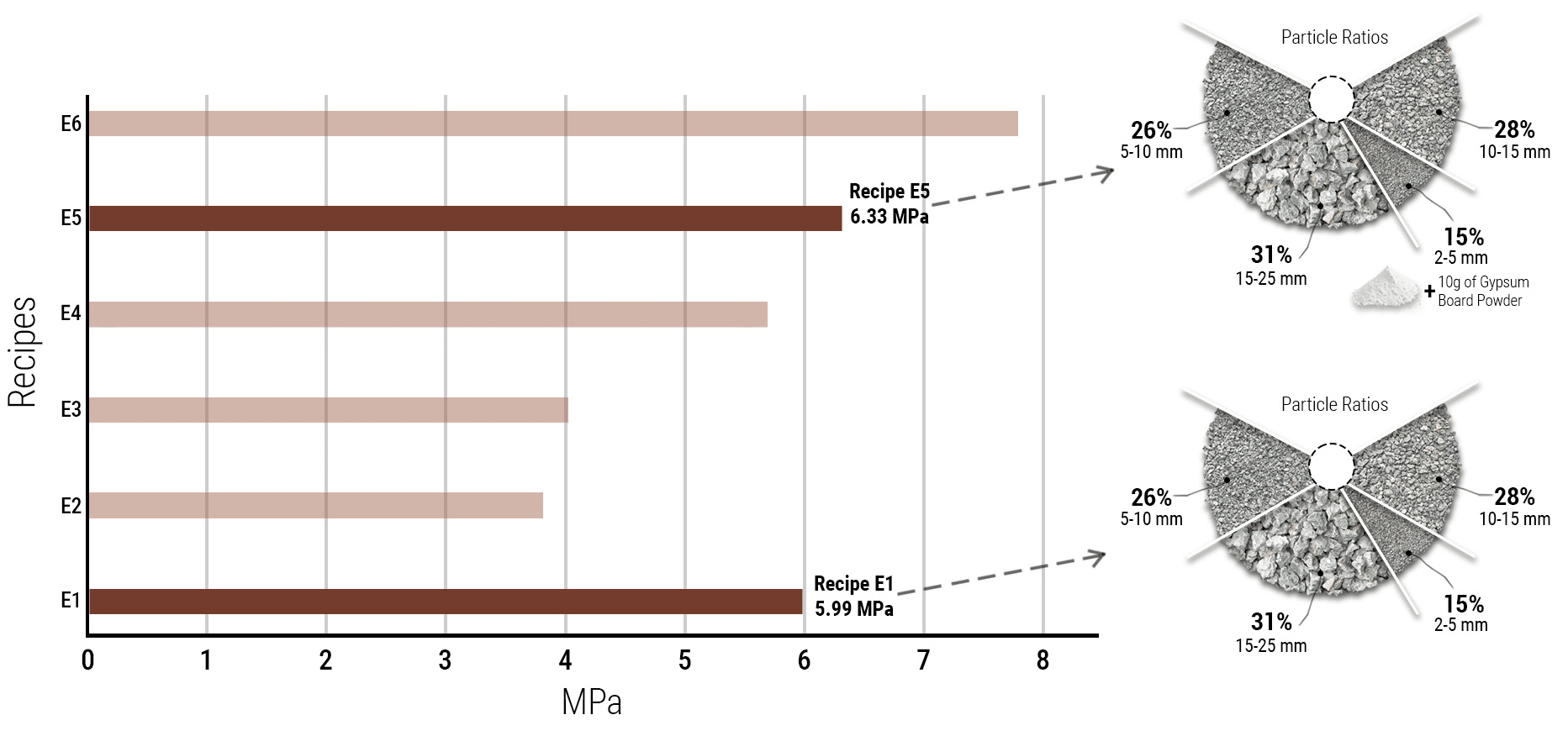
The same curing process was conducted for Experiment E, using a duration of 7 days. Compressive strength tests were then performed on all prototypes. The results show clear variation based on particle distribution and material composition. The best performance was achieved by recipe E6, which reached approximately 7.73 MPa. This indicates that combining aggregates with ceramic particles improves strength through superior interlocking and material interaction. Secondary results show that E5 and E1 reached 6.33 MPa and 5.99 MPa, respectively. Both are balanced mixes, suggesting that well-distributed particle sizes contribute significantly to structural performance.
Conclusion and Next Steps
Experiment E
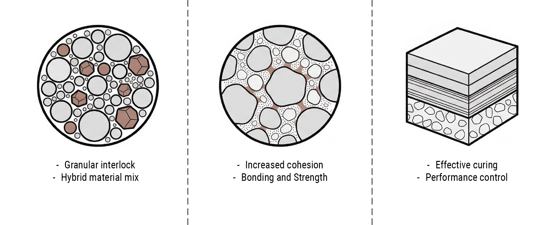
This experiment highlights three key findings: First, granular interlocking and hybrid material mixes improve performance. Second, the increase cohesion, bonding, and overall strength. And third, controlled curing plays a critical role in achieving consistent results.
Experiment F: Optimization
Fabrication Parameters
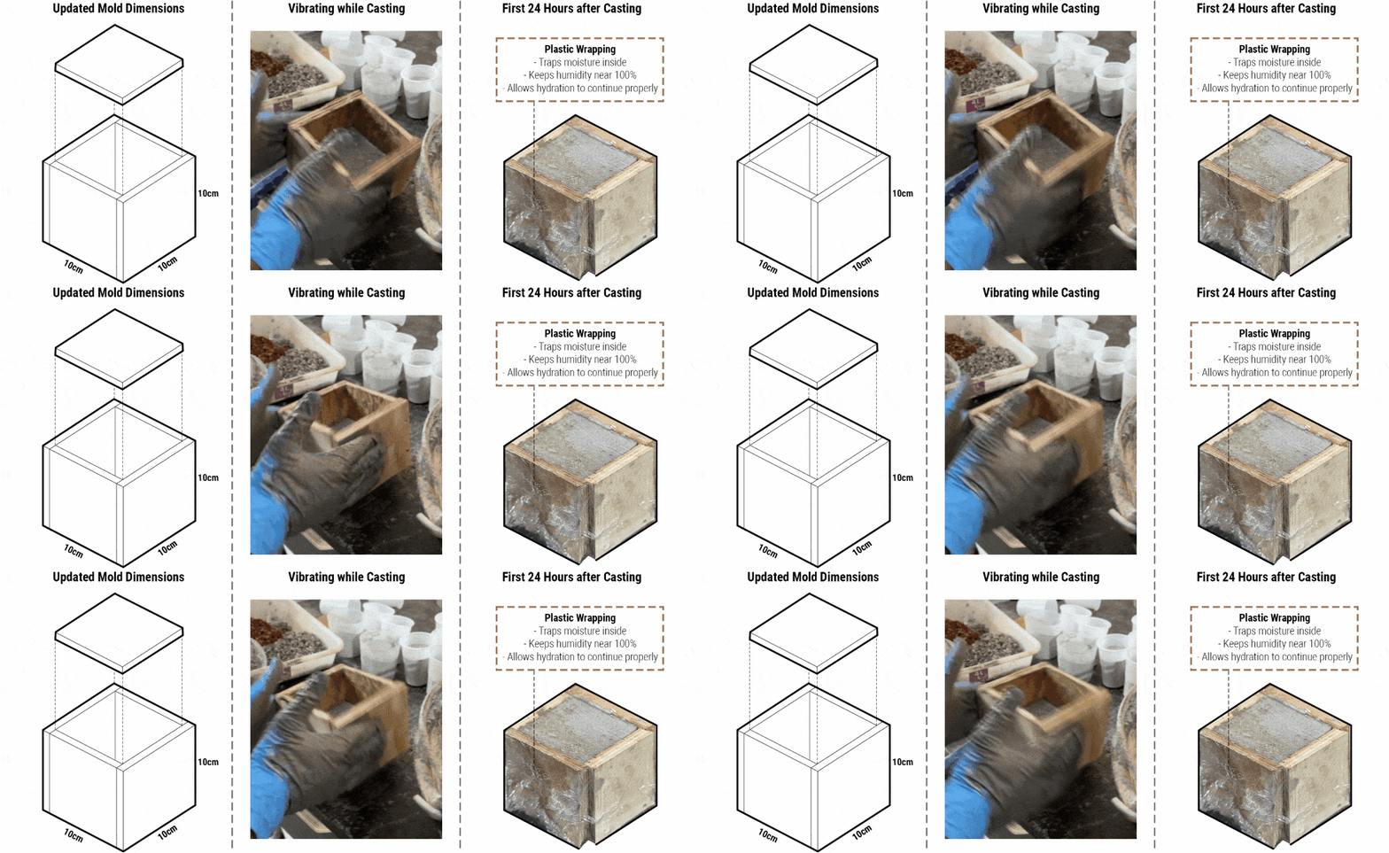
The research then progressed to Experiment F, where fabrication parameters were further refined by increasing the mold size to 10 cm and introducing vibration during casting to improve compaction. After casting, the molds were sealed with plastic for the first 24 hours to retain moisture and ensure proper hydration.
Formulation
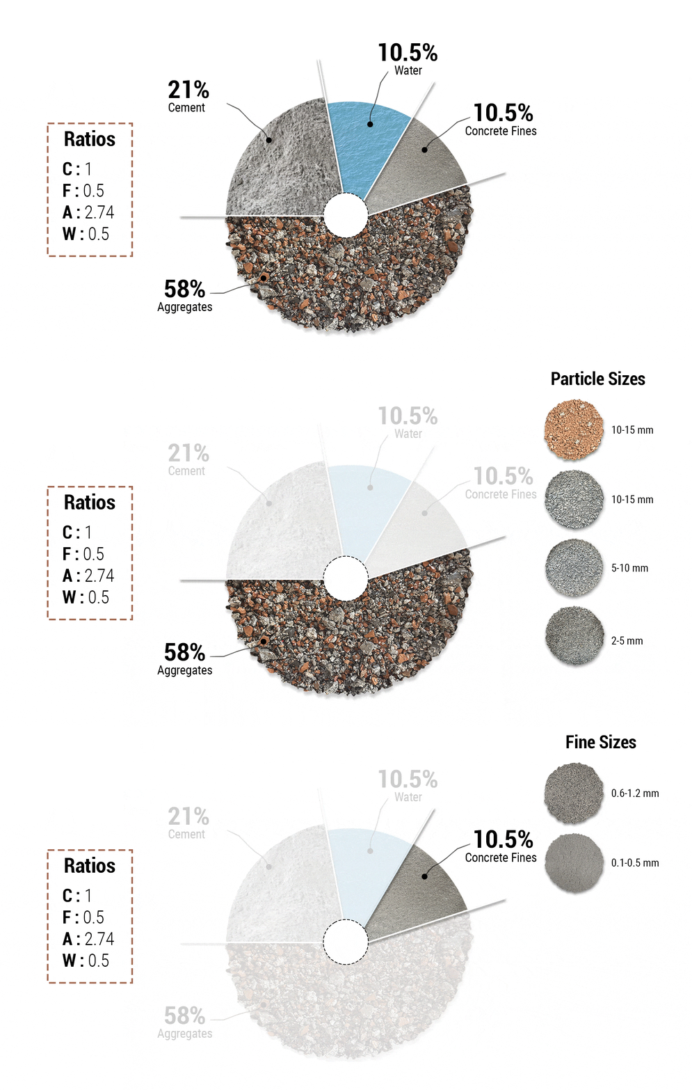
For this recipe, mix proportions were calibrated to match a 20 MPa concrete benchmark. Aggregate size was limited to below 15 mm, as larger particles were unsuitable for the mold scale and could compromise the reliability of compressive strength results. A finer particle range of 0.6–1.2 mm was also introduced, intended to function similarly to sand in conventional concrete mixes by improving packing density and cohesion.
Particle Sizes and Demolding
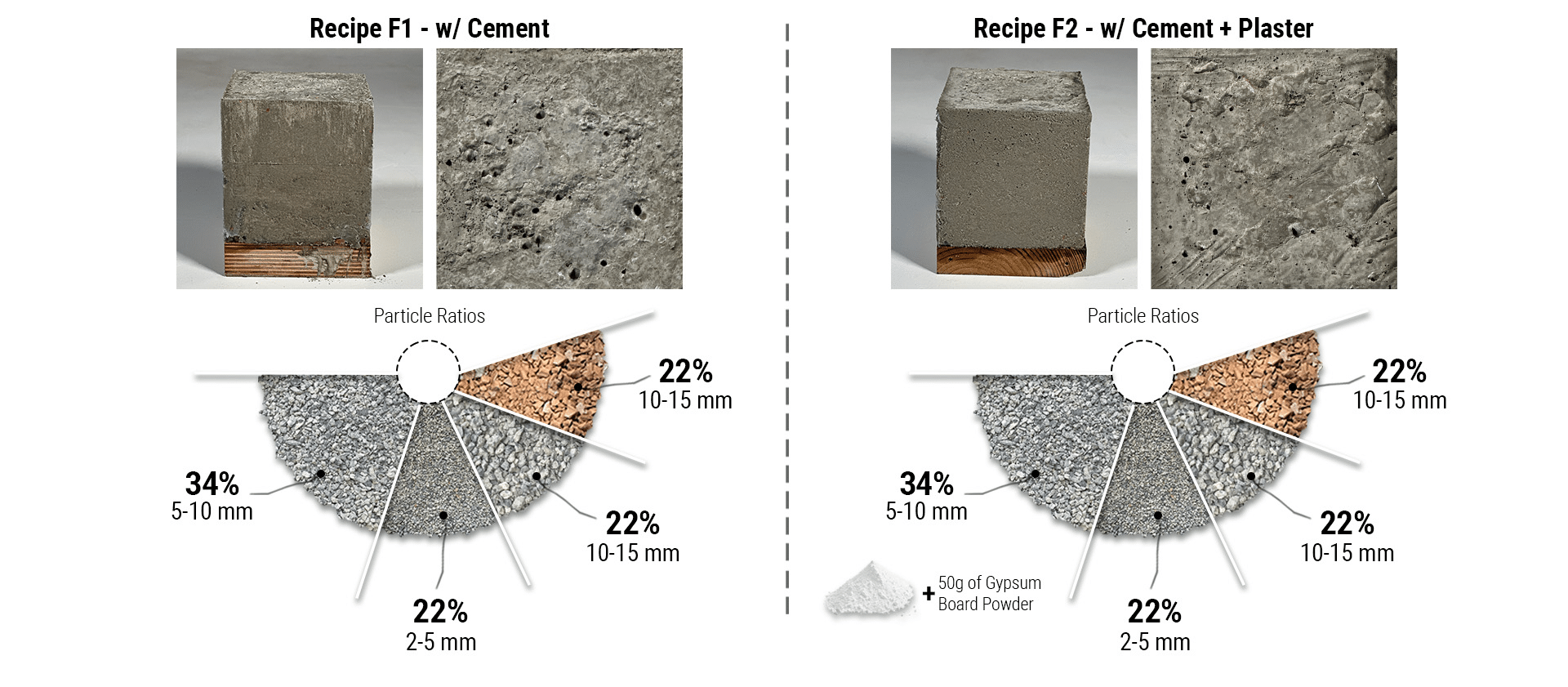
The particle distribution was balanced with a slight dominance of 5–10 mm sizes. The only variation between the two recipes was the addition of 10% gypsum board powder in the second mix.
Analysis and Best Performance
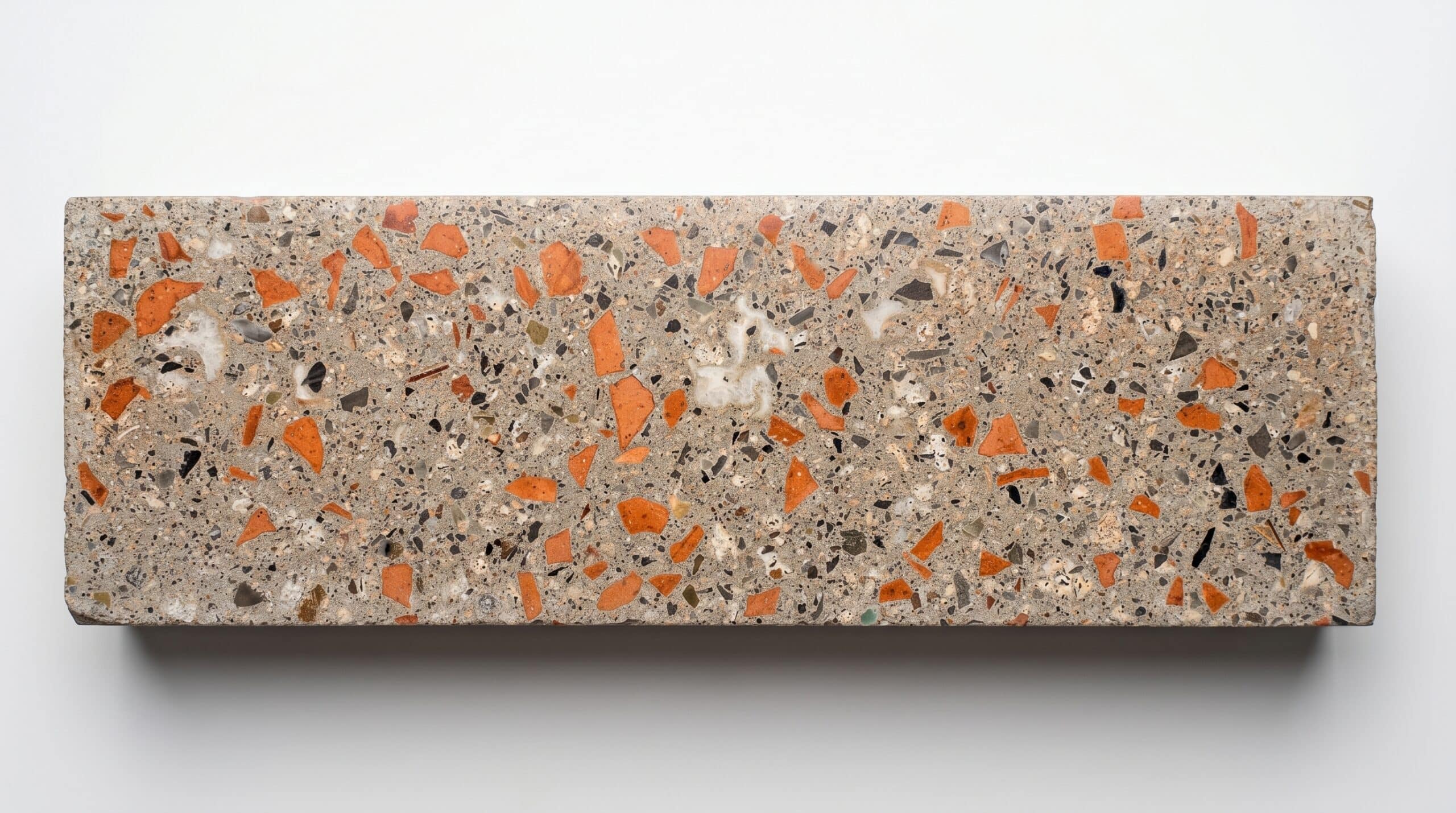
Finished Surface
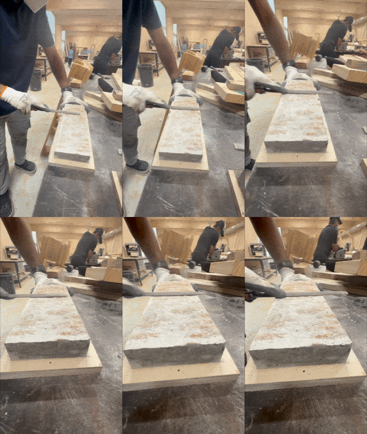
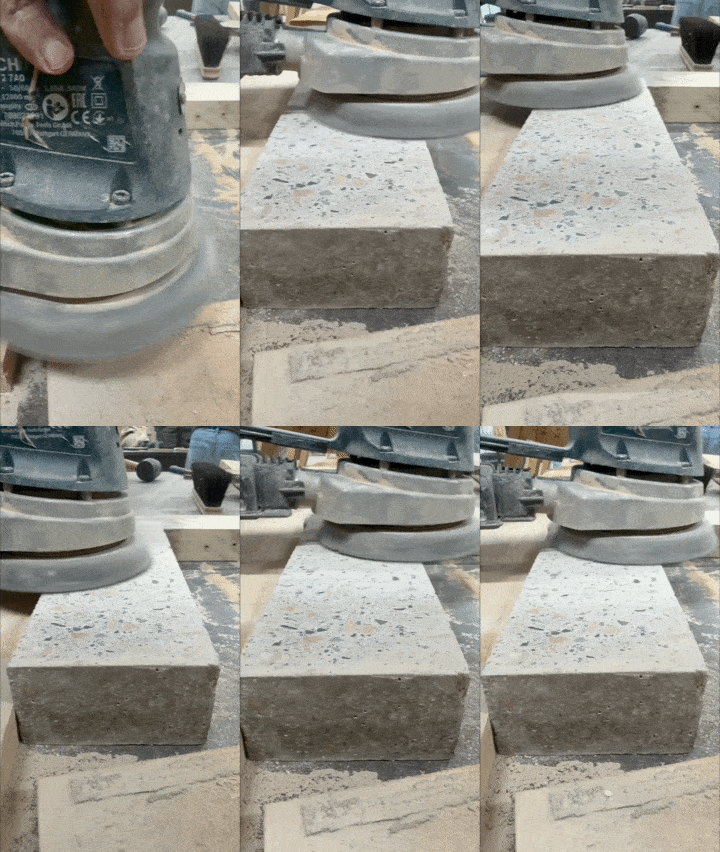
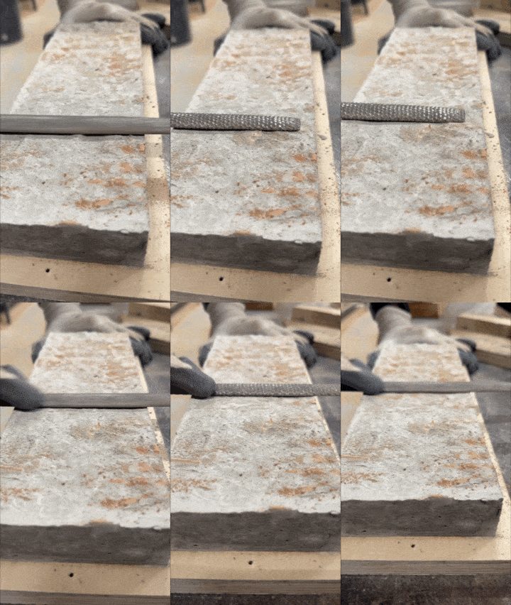
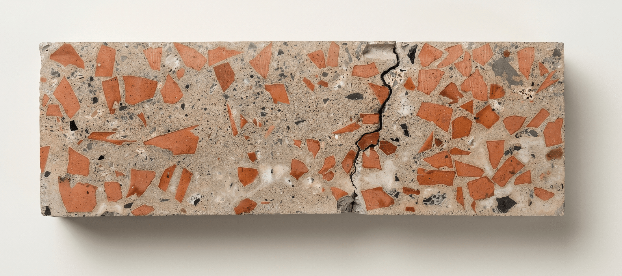
An aesthetic surface was achieved after sanding the top surface of our molds.
The Spanning Element Idea and Tension Tests
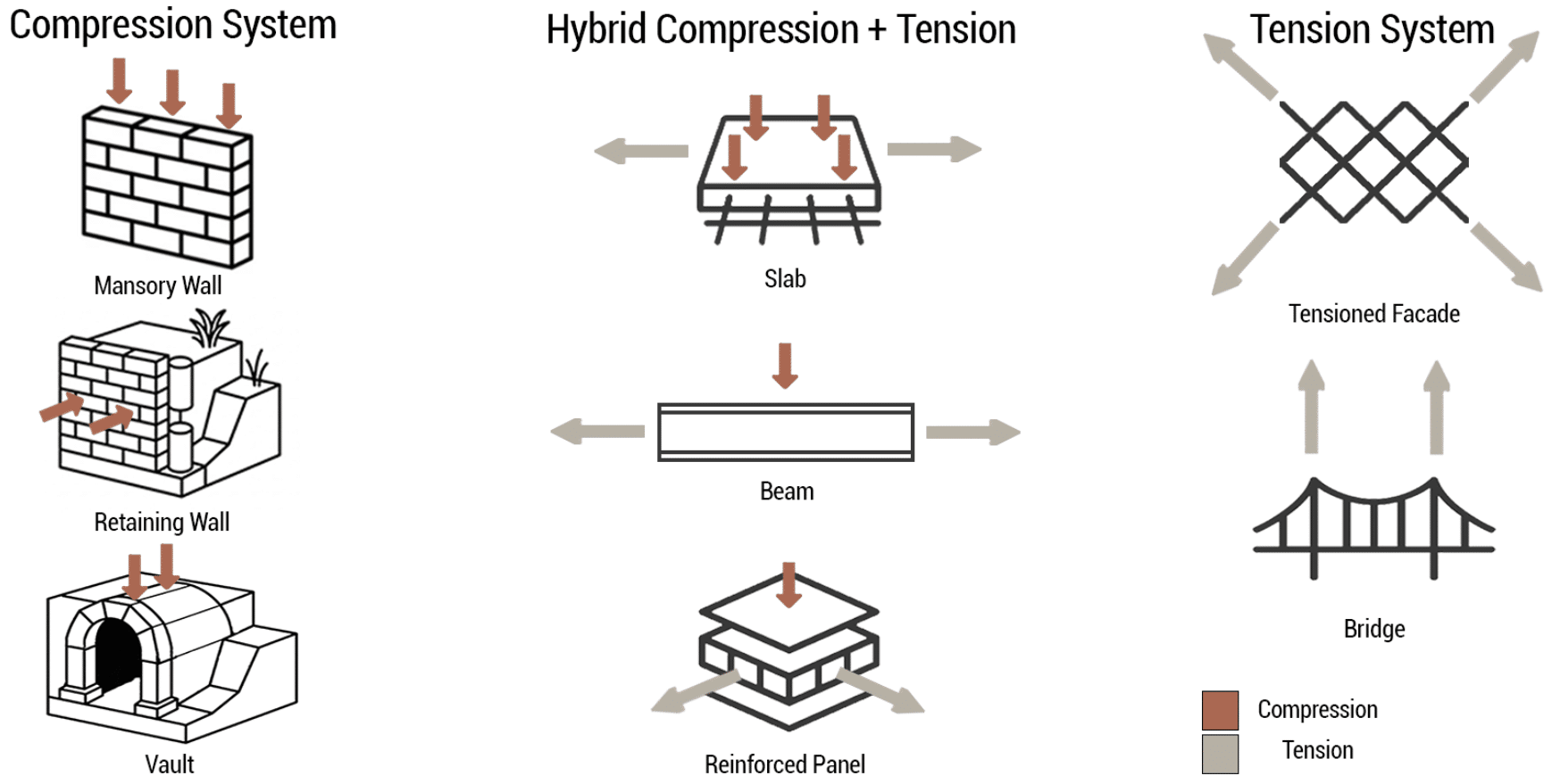
At this stage, the project transitions from compression-based systems to spanning elements, where tensile performance becomes critical. The focus shifts toward introducing tensile capacity within a predominantly compressive CDW material system.

Architectural Systems
From Vertical Wall Elements to Horizontal Spans
CDW-based systems typically perform well in compression, similar to masonry or vault structures. However, spanning systems require a hybrid approach that combines compression and tension. This leads to the exploration of reinforced slab systems and tension-integrated structural strategies.
Spanning Element Focus
State of the art for the Spanning Element System
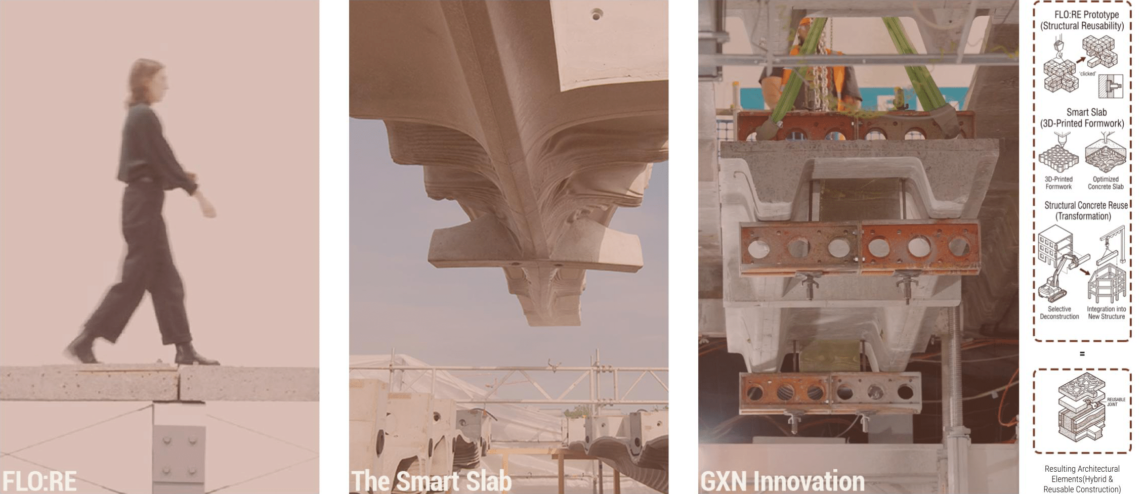
Precedents such as the Smart Slab and structural reuse projects demonstrate how geometry and fabrication enable efficient spanning systems. These references inform the development of a ribbed, material-efficient slab system.
Experiment Set G: Bio-based Tension Systems
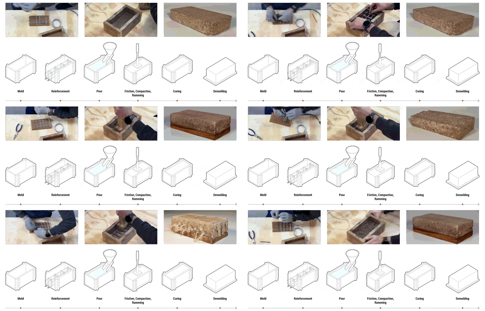
Fabrication Parameters
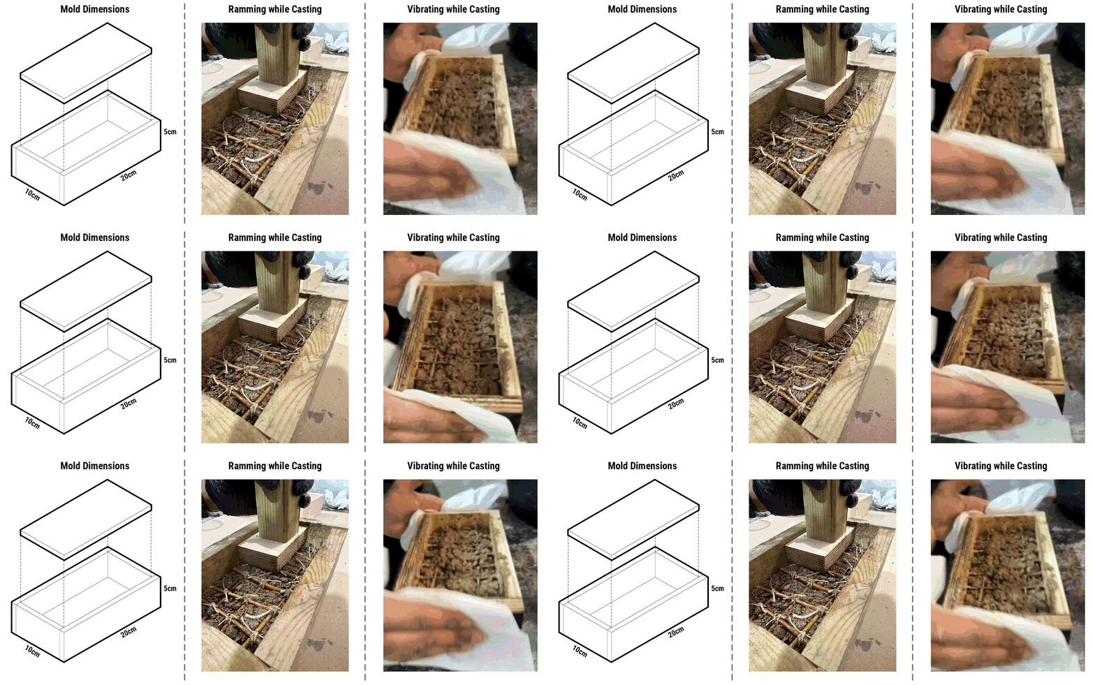
Initial prototypes explored fabrication methods such as ramming and vibration during casting. These tests highlighted the role of compaction in influencing density, bonding, and overall material performance.
Formulation and Tensile Systems
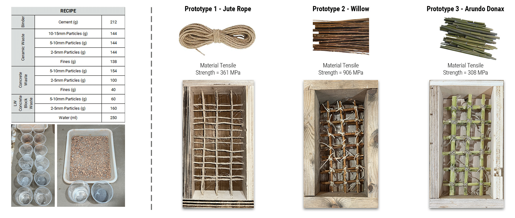
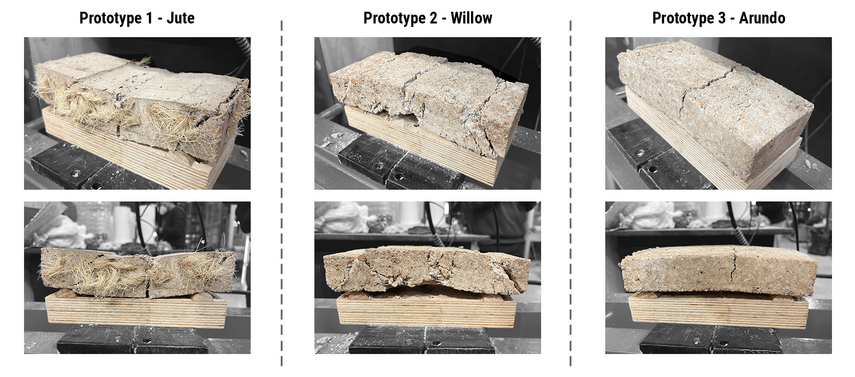
Bio-based materials, including jute, willow, and arundo donax, were tested to introduce tensile capacity. While these improved cohesion, their structural contribution remained limited and inconsistent.
Demolding
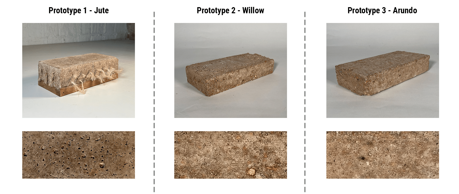
Post-demolding observations revealed variations in surface quality and internal bonding. The material exhibited brittle behavior, particularly under tension-dominated conditions.
Flexural Performance Tests Experiment G
Analysis and Best Performance
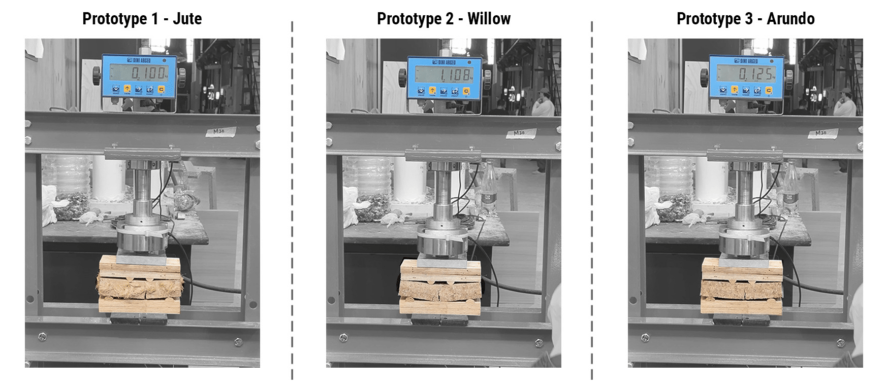
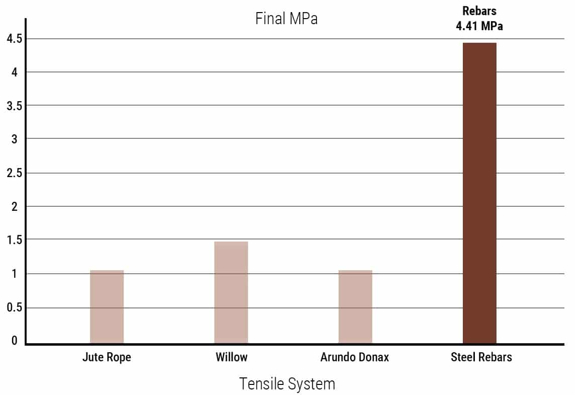
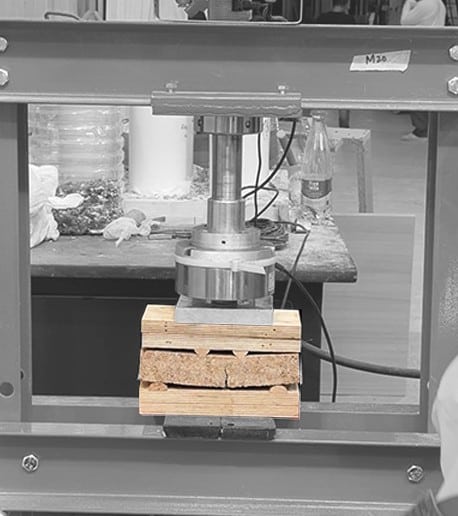
Flexural tests showed incremental improvements across iterations; however, performance remained insufficient for structural applications. This indicated that material modification alone could not resolve tensile limitations.
Visual Analysis
Failure patterns revealed brittle cracking and lack of tensile continuity. The system demonstrated sudden failure rather than gradual load redistribution.
Formulation & Tensile Systems
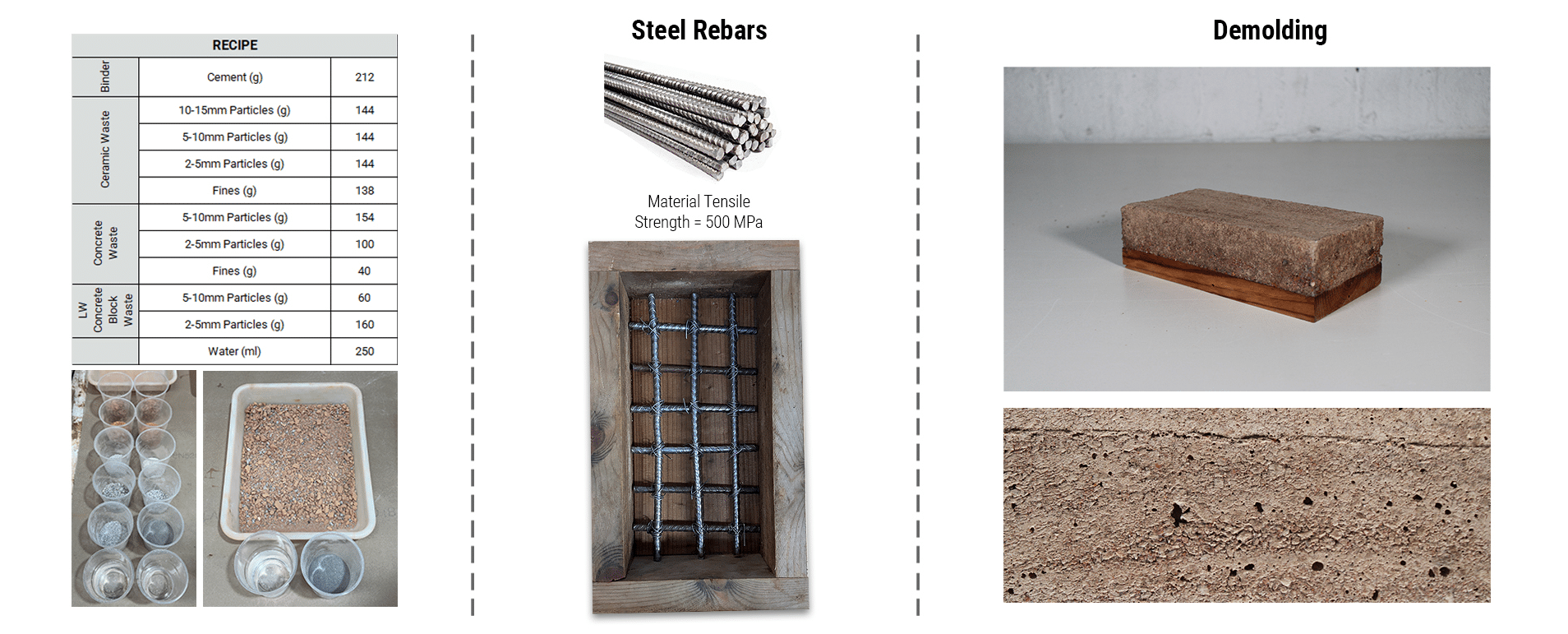
These limitations led to the integration of reclaimed steel rebars sourced from construction waste. The system evolves into a hybrid model, where compression is managed by the CDW composite and tension by steel reinforcement. Cement remains the only new material introduced, while all other components are reclaimed.
Analysis and Best Performance
The highest flexural performance was achieved using steel rebars, reaching 4.4 MPa.
Experiment Set H Tension Systems
Fabrication Parameters
The mold dimensions were increased, and vibration was introduced during casting to improve specimen quality.
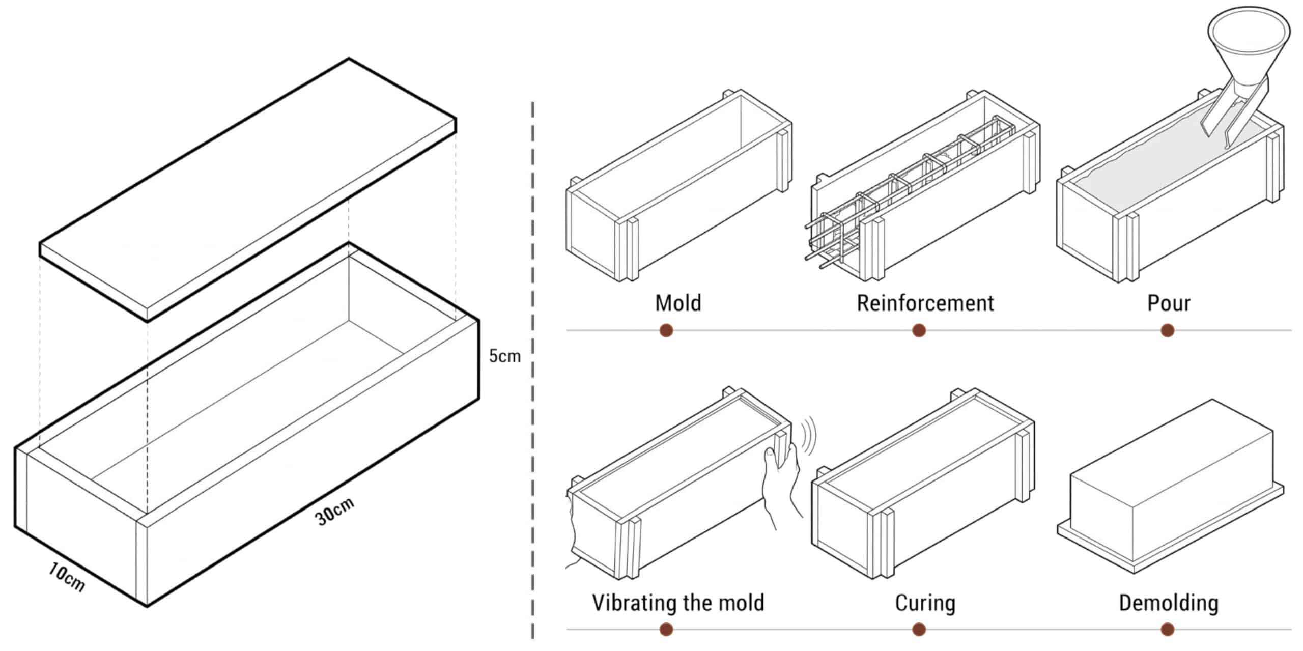
Tensile Systems
Four different reinforcement systems were evaluated to understand how each strategy influenced the structural behavior of the recycled concrete slabs. This comparison established the basis for identifying the most efficient reinforcement solution.
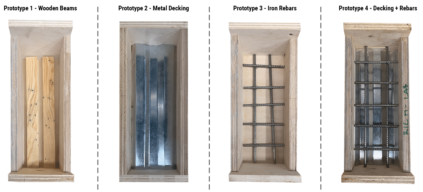
Demolding
Each reinforcement strategy represented a different approach to resisting tensile forces within the slab. The systems included wooden supports, metal decking, steel rebars, and a hybrid solution combining metal decking with steel rebars, allowing both conventional and alternative reinforcement methods to be assessed.
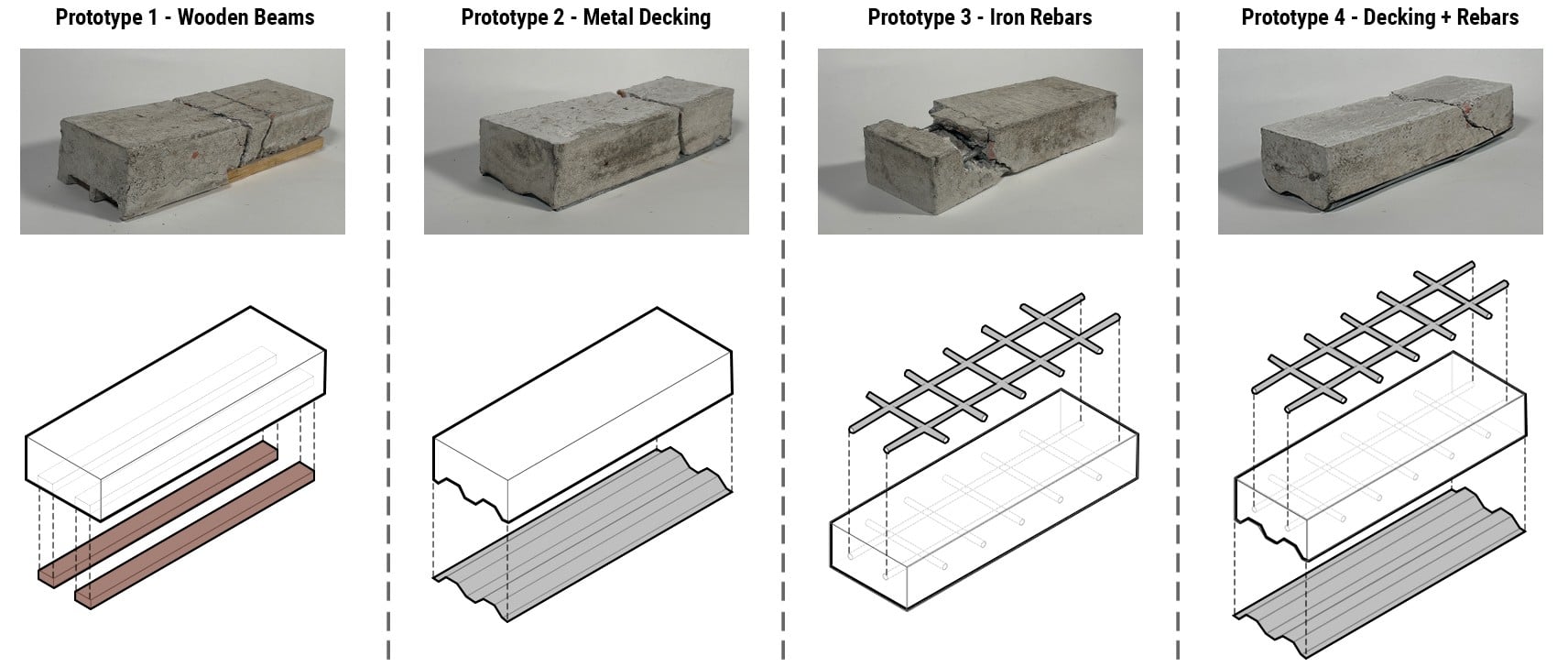
Analysis and Performances
As anticipated, the hybrid system combining metal decking and steel rebars delivered the highest flexural performance during testing. The combination provided greater stiffness and more efficient load transfer than the individual reinforcement systems.
Although the hybrid system performed best, the wooden beam configuration also exceeded the benchmark value. This result highlighted the potential of timber as a viable low-carbon reinforcement alternative deserving of further investigation.
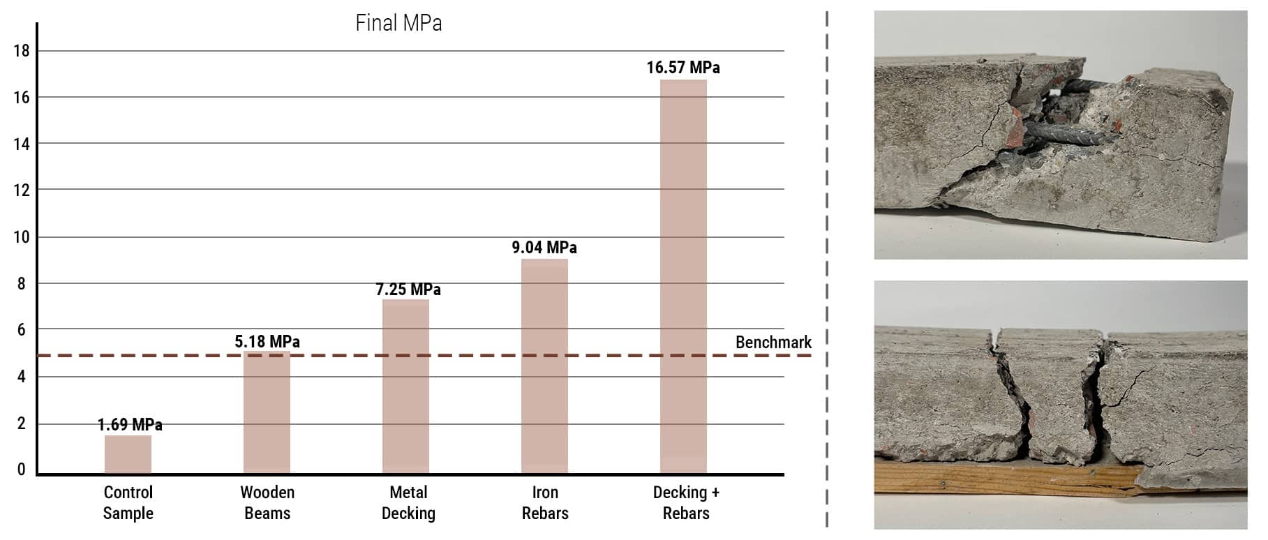
Tensile Systems
Following the initial comparison, the research shifted its focus toward the tension reinforcement systems that had shown the greatest potential. Three additional experimental configurations were therefore developed and tested.
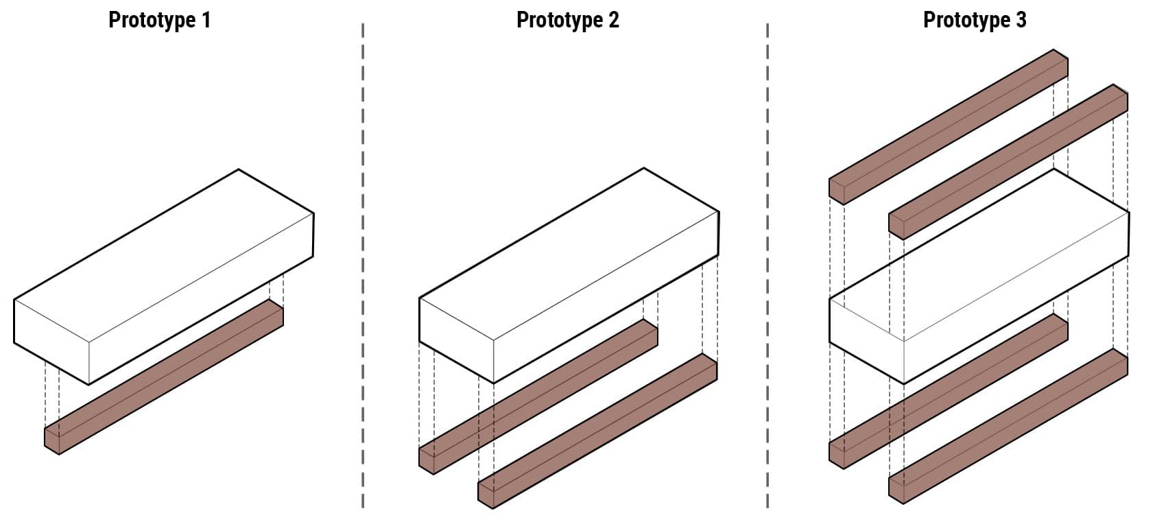
Among these, the wooden beam reinforcement system was investigated in greater detail. Different beam arrangements were explored to determine how the number and position of the timber elements influenced structural performance.
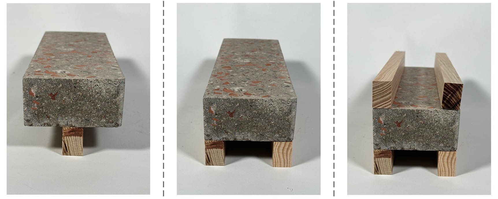
Best Performances
The flexural tests demonstrated that placing two wooden beams within the bottom tension zone produced the most promising results. This configuration significantly improved bending resistance and was therefore selected for further development.
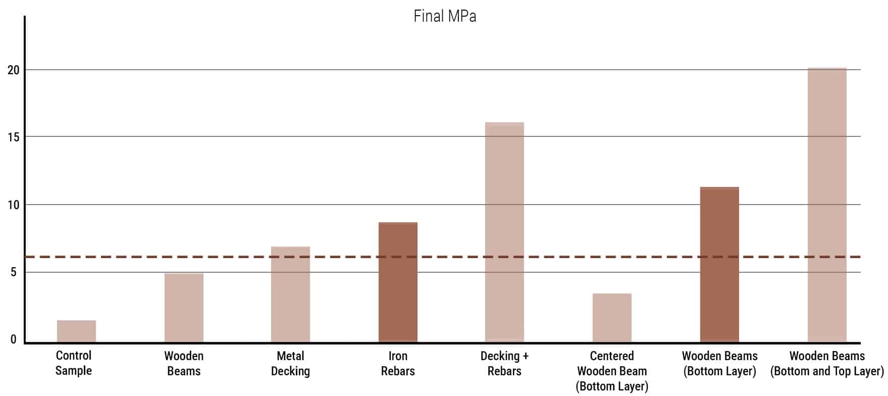
The results from all flexural experiments were compiled and compared to provide a comprehensive overview of the performance of each reinforcement strategy. This comparison made it possible to identify the strongest candidates for the next stage of the research.
The comparison revealed that both steel rebars (9.04 MPa) and the configuration using two wooden beams (11.77 MPa) exceeded the benchmark value. These two systems emerged as the most promising reinforcement solutions and became the primary focus for the continued development of the slab system.
Scaling Up: Building Systems, Joint Systems and Final Prototype
Material Prototype to Building System
Translation across Scales
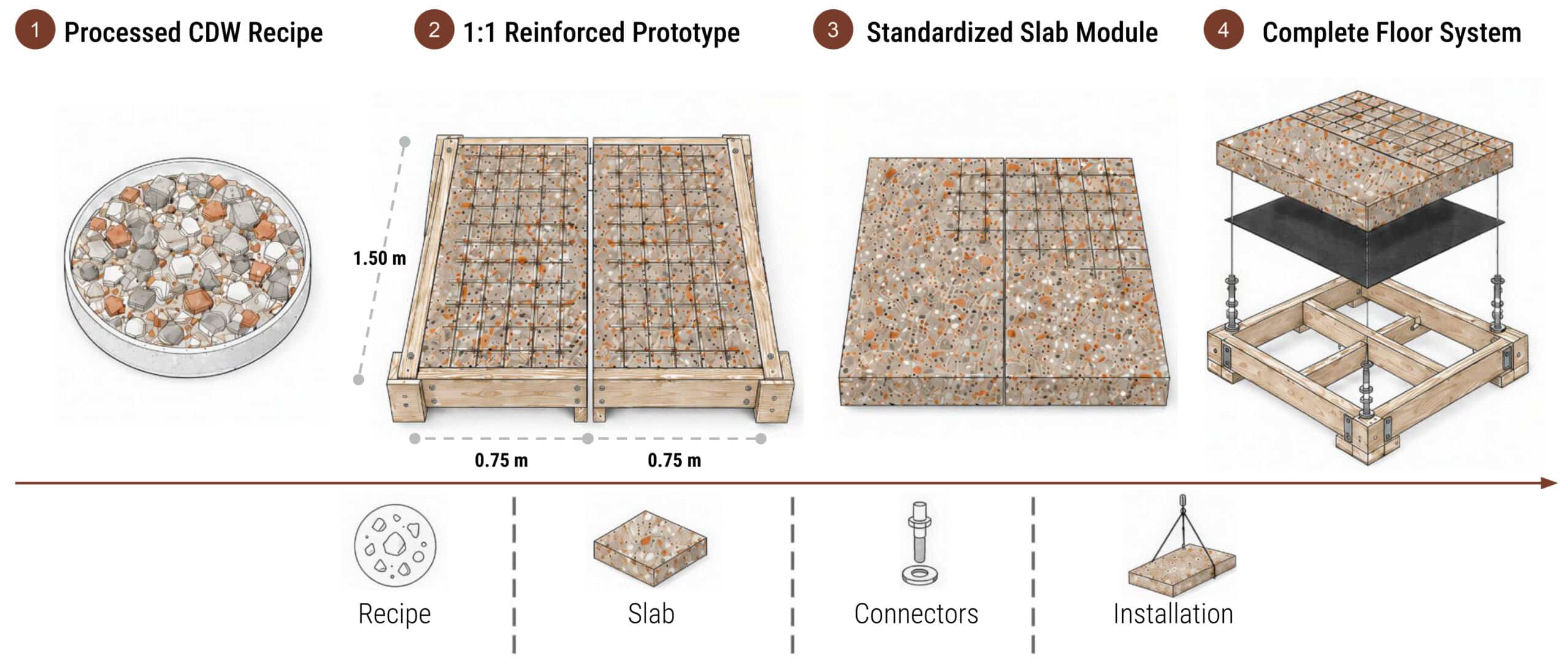
ReCast evolves from a processed CDW material recipe into a reinforced prefabricated slab system. The workflow progresses from material preparation to a full-scale prototype, then to a standardized module, and ultimately to a complete floor assembly.
Market Position and Application Range
Three Proven Construction Solutions
The system was evaluated across timber, concrete, and steel structural frameworks, each presenting distinct span requirements, structural logic, and market applications.

Product Family
Prototype Module to Floor Catalogue
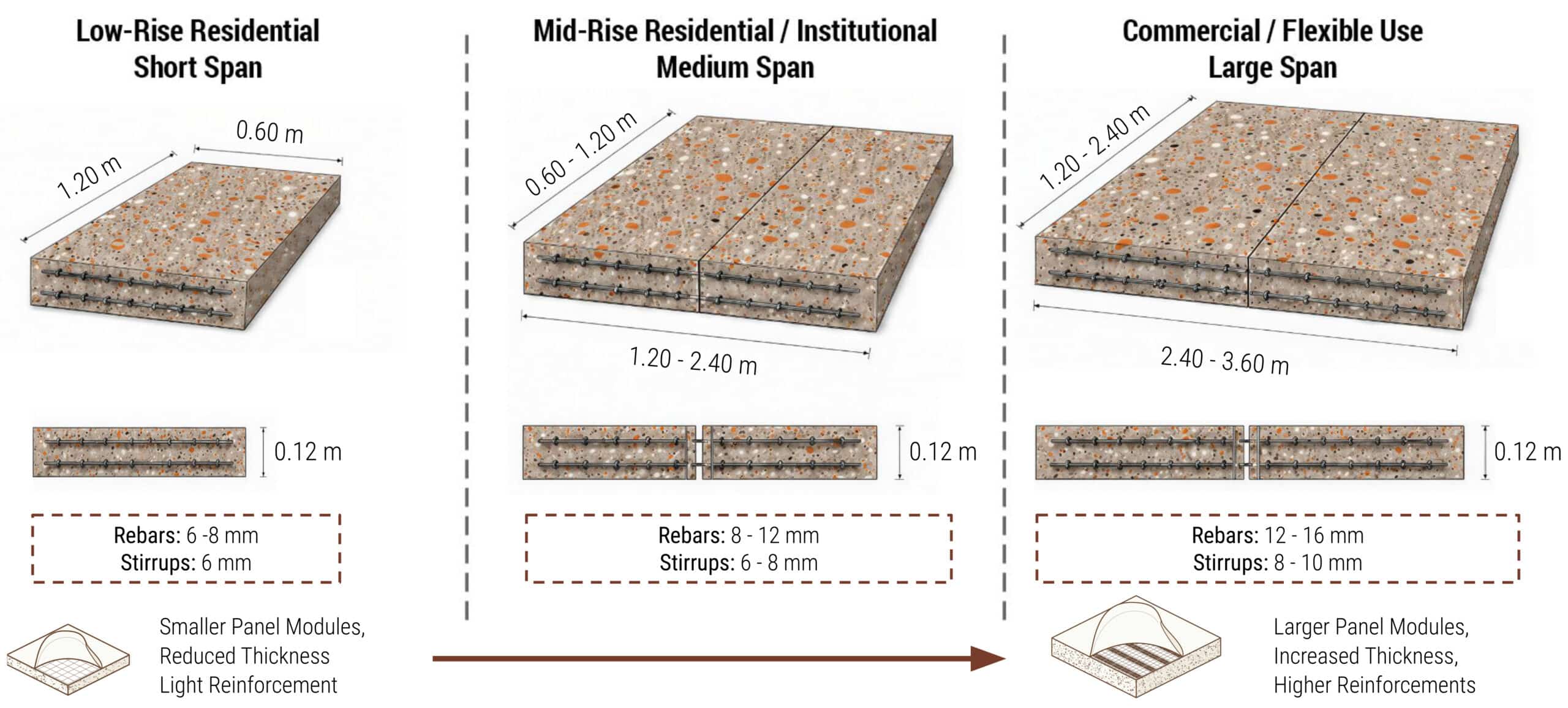
The prototype served as the basis for a slab catalogue featuring short-, standard-, and long-span configurations, with variations in panel dimensions, reinforcement, and structural capacity.
Standardized Connection Kit
Panel Connectors
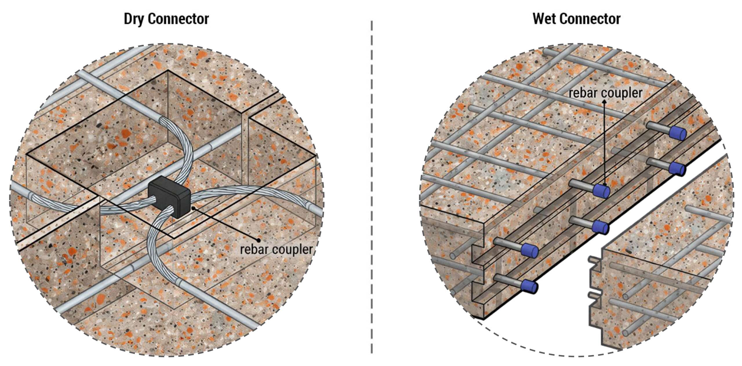
Dry connectors were introduced to facilitate rapid assembly and future disassembly, while wet connectors employing couplers were designed to provide structural continuity where greater integration was required.
Three Interface Families for Multiple Construction Systems
A connection kit was developed to define the interface between the slab system and different structural frames, addressing support, alignment, tolerances, and fixing requirements.

Timber System
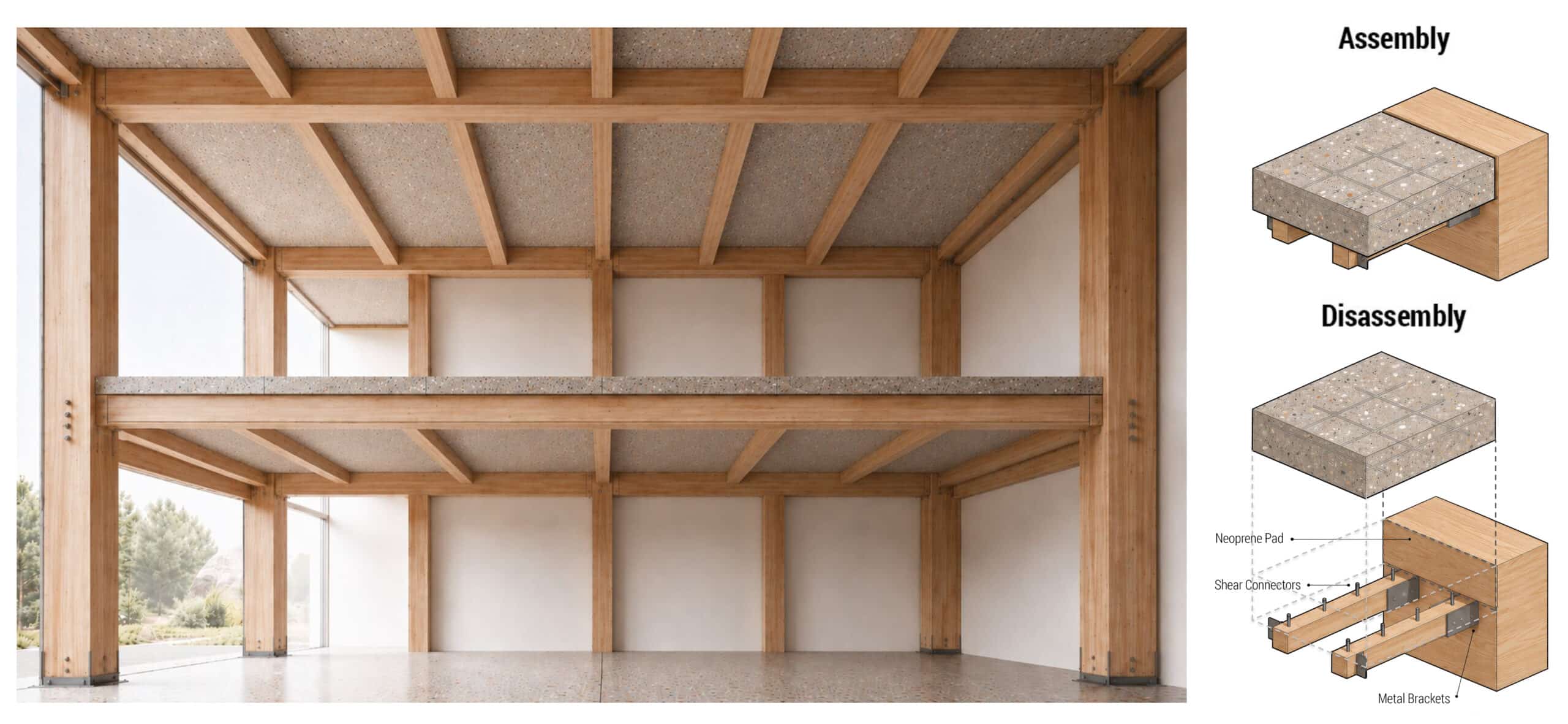
Dry Floor System for Timber Construction
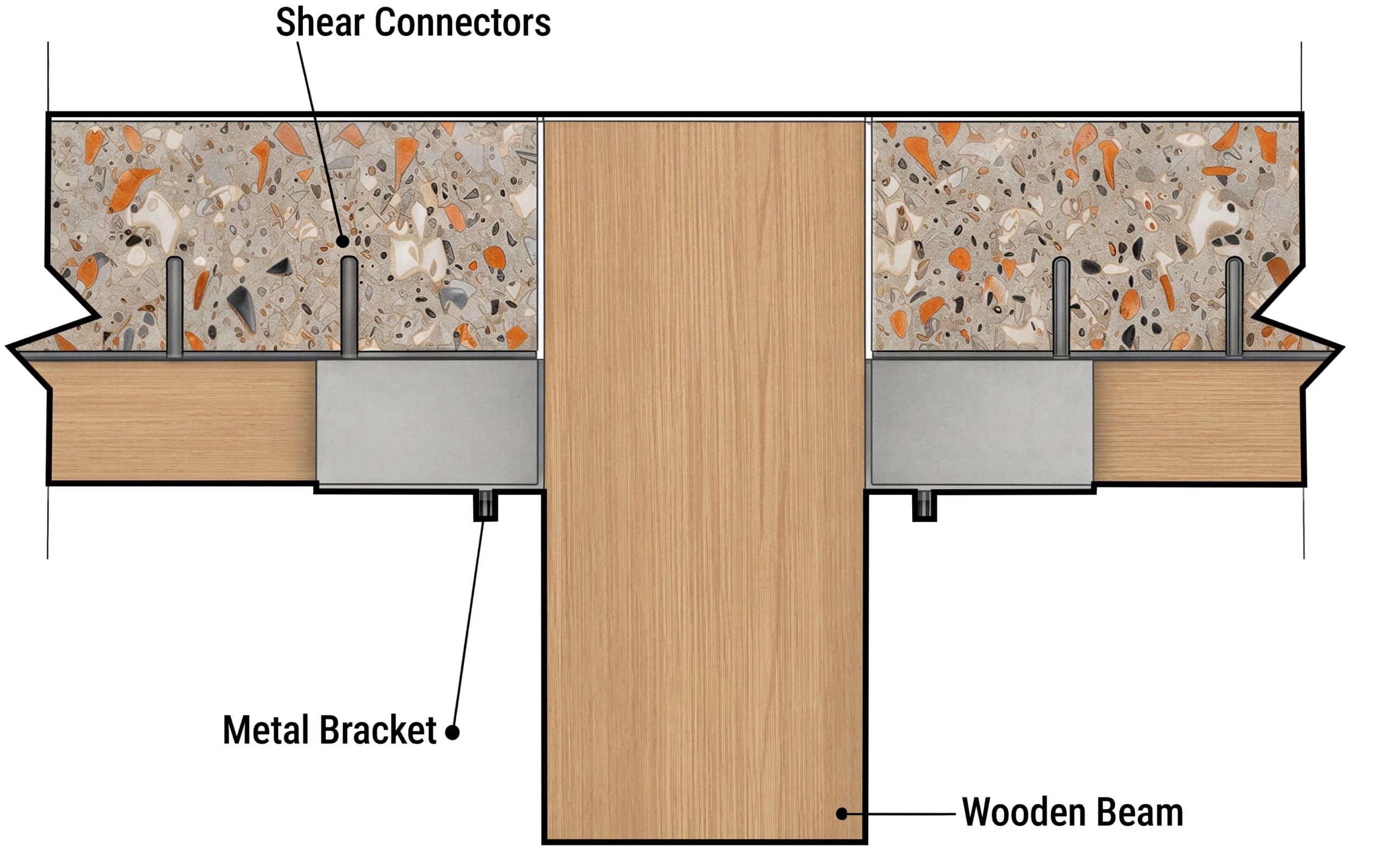
For timber construction, the slab bears on neoprene pads supported by a steel seat, while brackets and connectors provide restraint. This configuration enhances mass and durability while preserving a dry and accessible construction system.

Concrete System
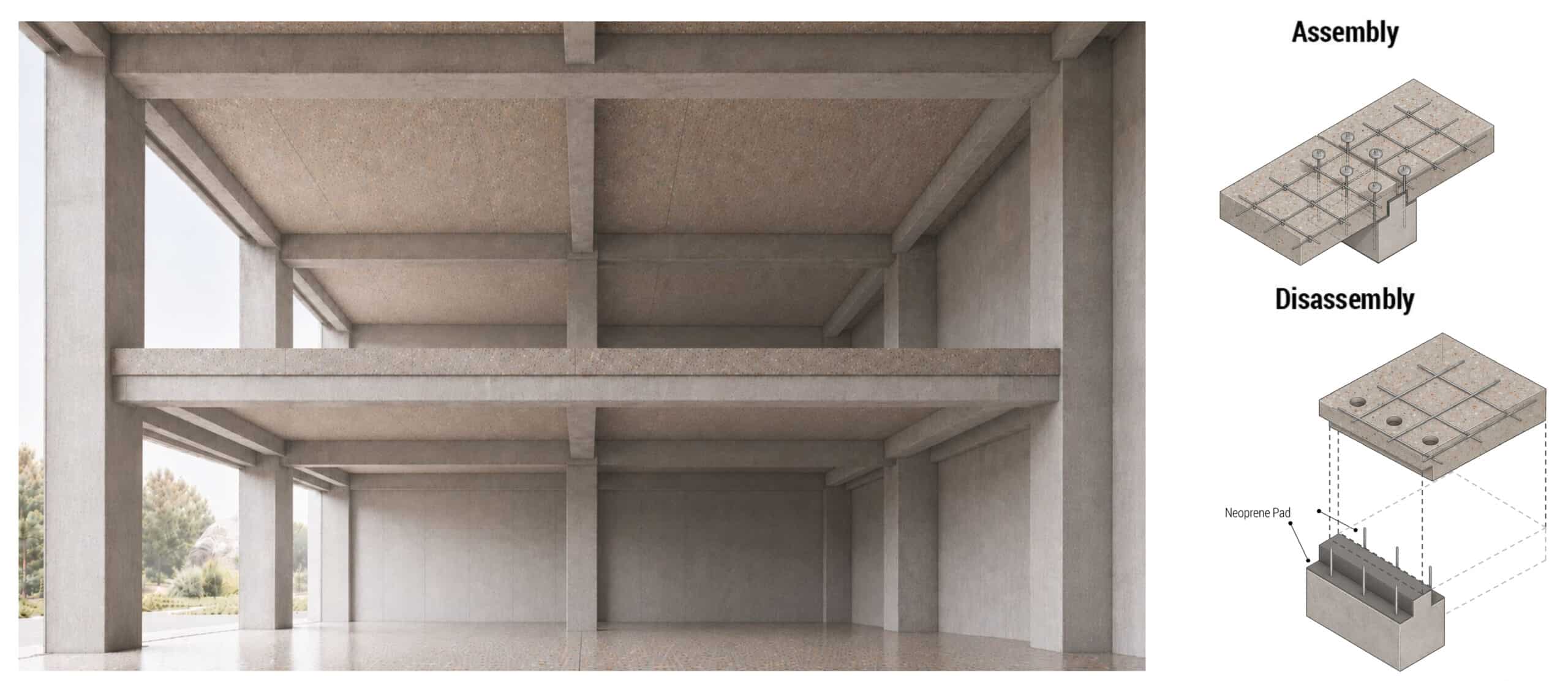
Continuous Floor System for Concrete Frames
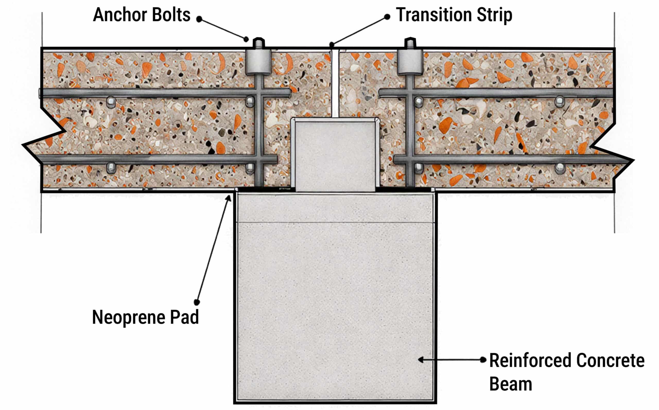
Within concrete construction, the system follows conventional precast principles using bearing ledges, neoprene pads, anchors, and reinforcement continuity, making it suitable for mid-rise residential and institutional buildings.

Steel System
Rapid Floor System for Steel Frames
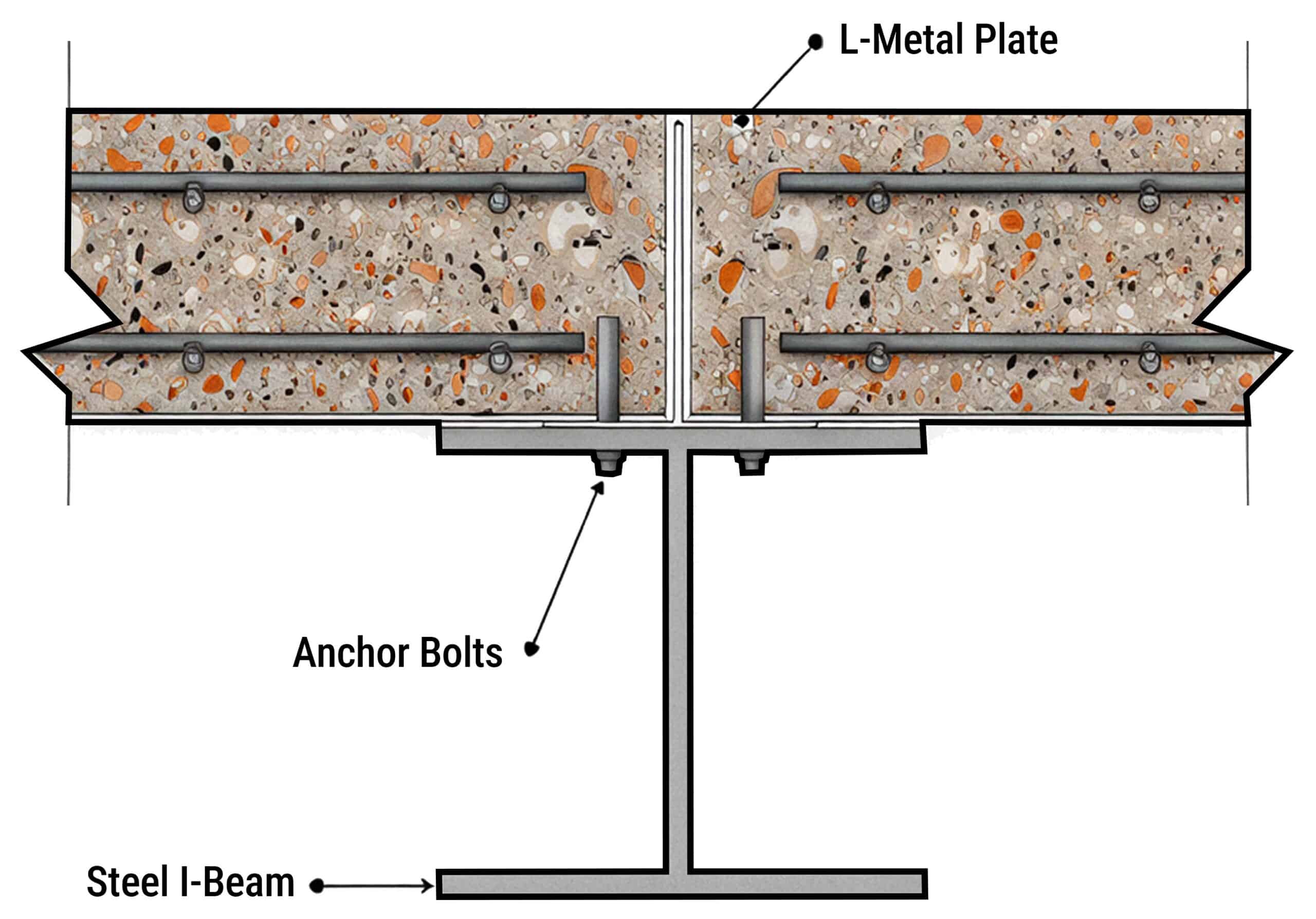
In steel construction, a dry L-plate interface with bolted restraint enables rapid installation and accessible connections, supporting wider spans and flexible commercial floor layouts.
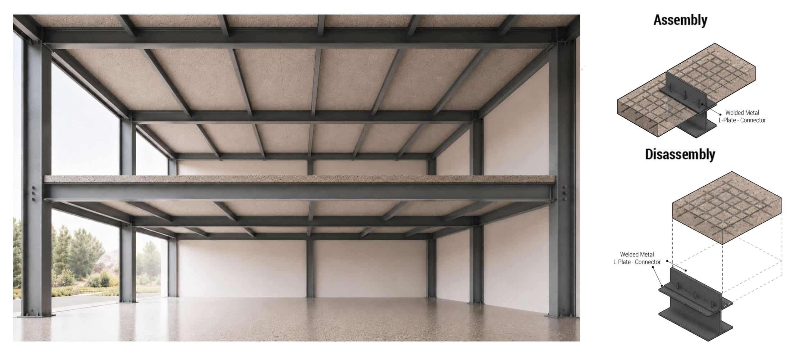

Prefabricated Slab Installation
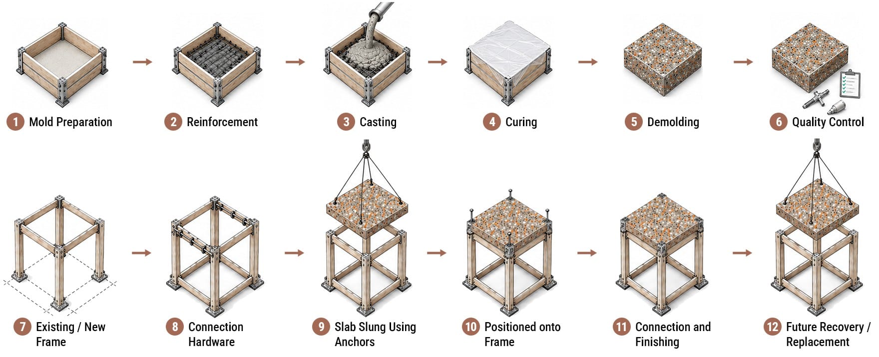
Controlled Assembly and Disassembly Sequence
Production follows a sequence consisting of mold preparation, reinforcement placement, casting, curing, demolding, and quality control. On-site installation consists of frame preparation, lifting, positioning, fixing, and potential future recovery.
Final Prototype
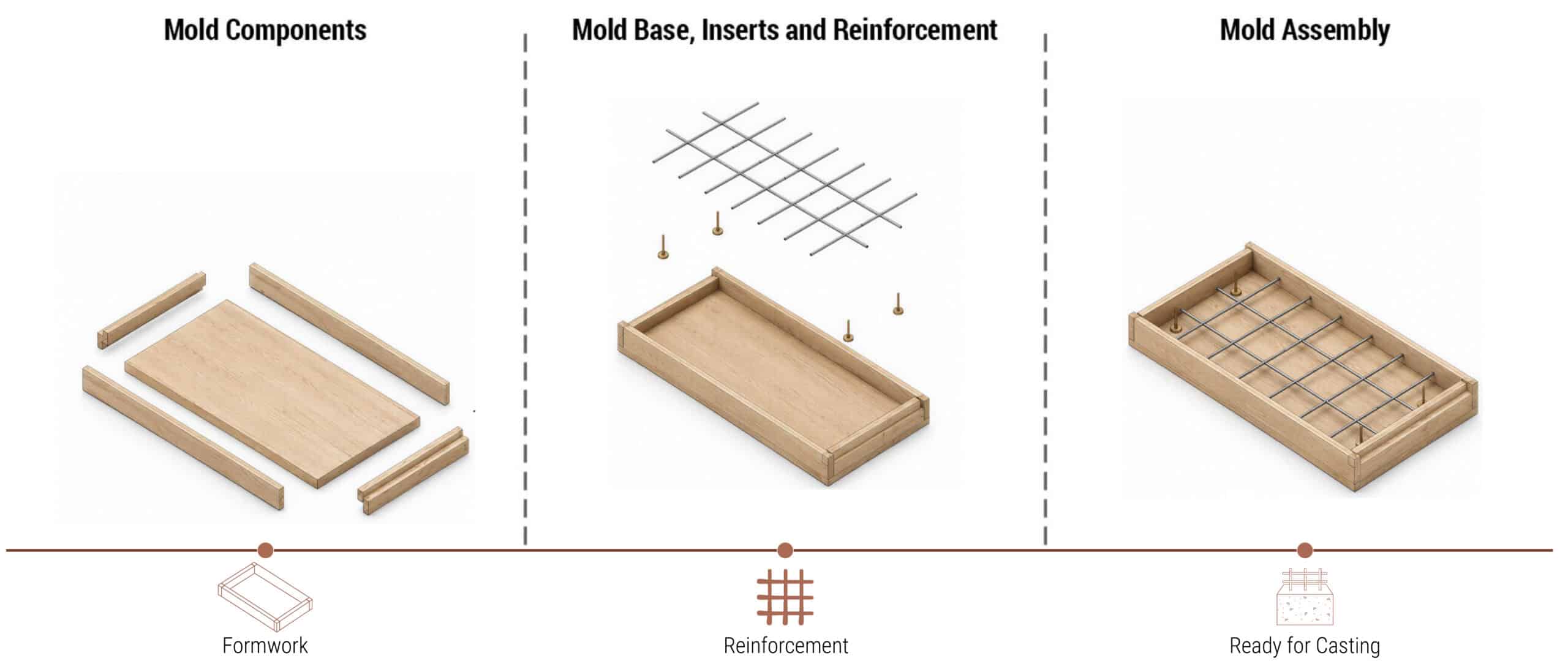
Mold Preparation
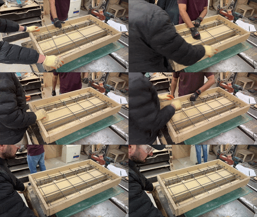
The full-scale prototype begins with accurately fabricated formwork, where mold precision, inserts, and reinforcement placement determine the quality of the finished element.
Fabrication Process
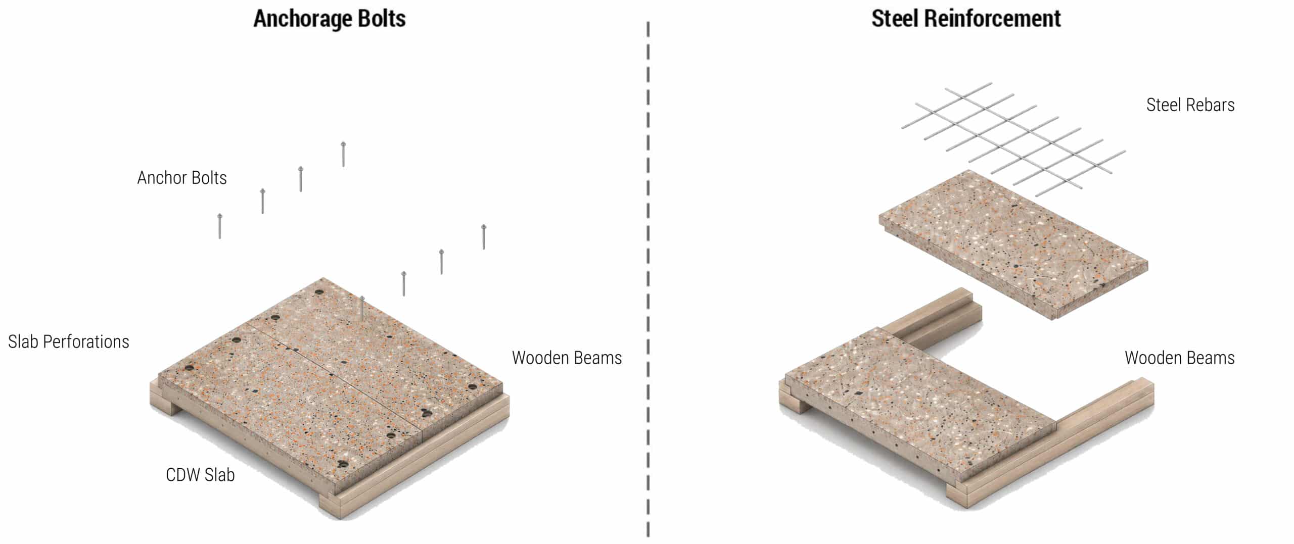
Anchors, slab perforations, timber supports, and reinforcement grids organize the prototype as a representative construction component rather than merely a material sample.
Exhibition Prototype 1:1
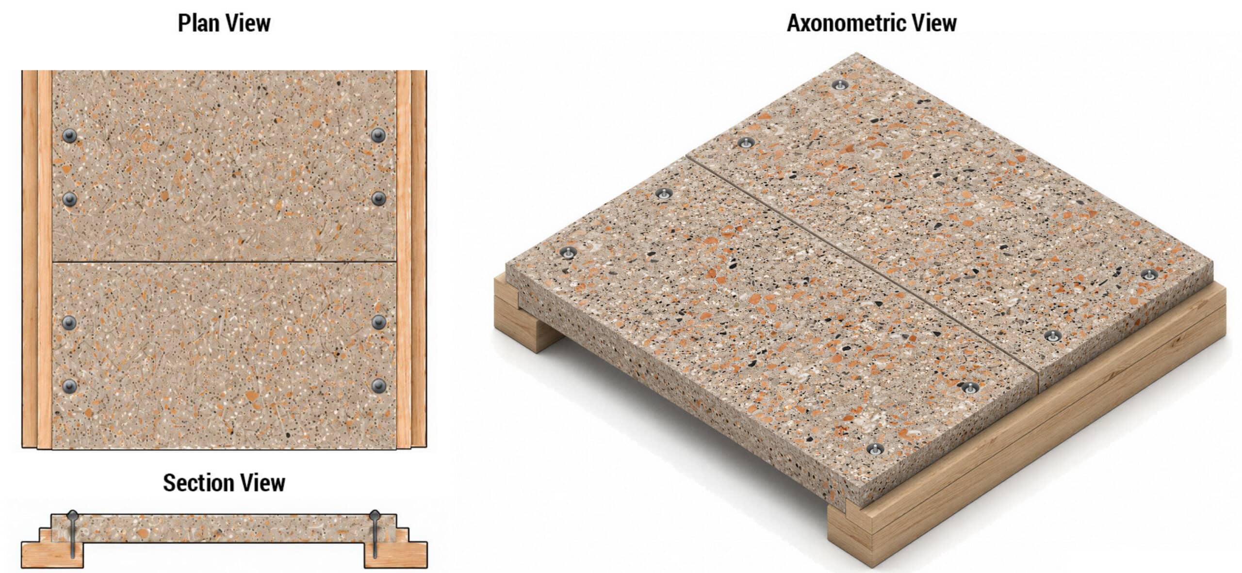
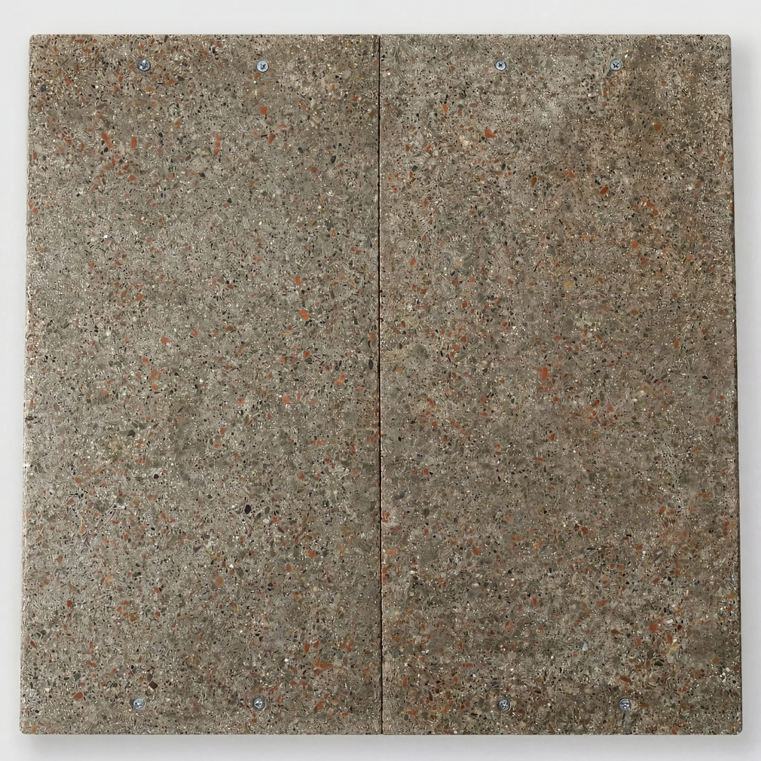
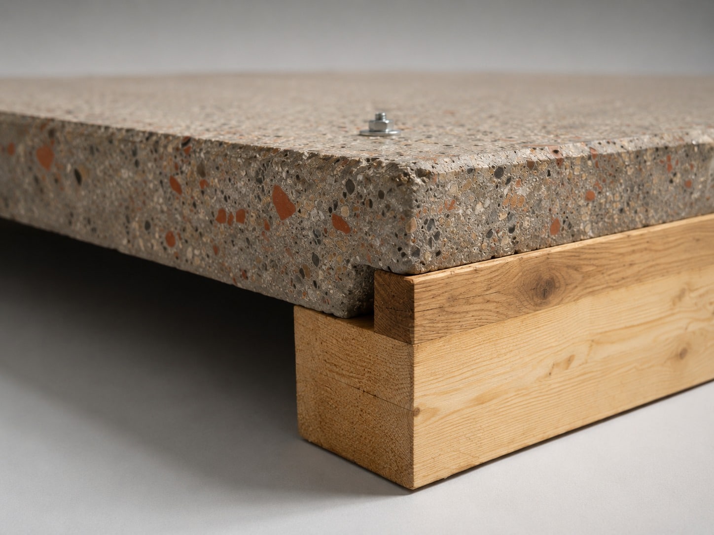
The completed prototype measures 1.50 × 1.50 m with a slab thickness of 120 mm. Plan, section, and axonometric drawings illustrate the support conditions, anchorage, joints, slab thickness, and exposed recycled aggregate texture.
Fabrication Process
Final Prototype Images
ReCast demonstrates how material research can be translated into a prefabricated floor system.
Performance and Analysis
Calculating Embodied Carbon
Computational Logic
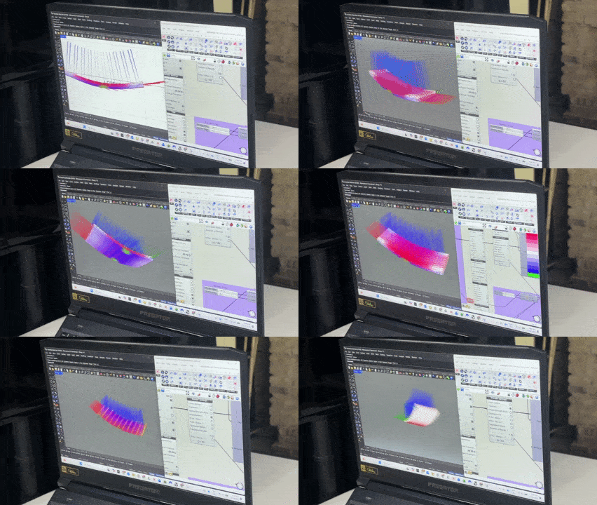
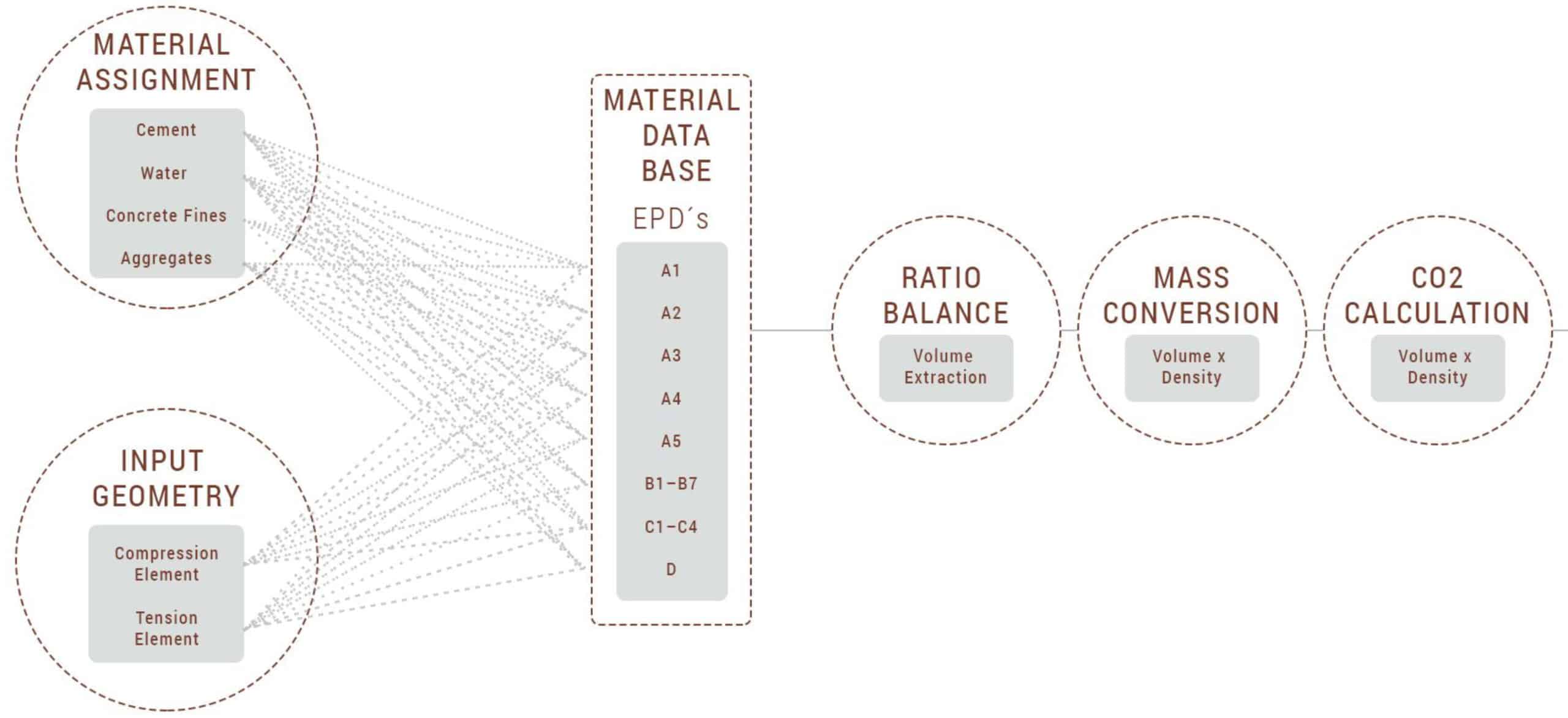
A workflow was developed to integrate material quantities with Environmental Product Declaration (EPD) data, enabling automated embodied carbon calculations from stages A1 to D.
Lifecycle Carbon Comparison
From Waste to Structure
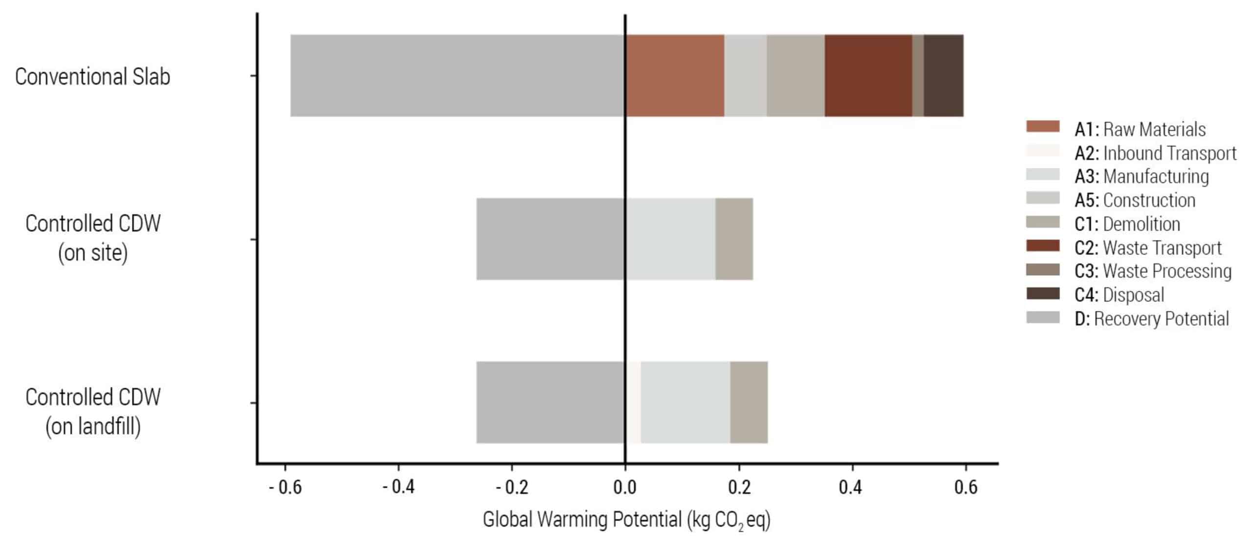
Conventional concrete slabs were compared with CDW-based slabs produced using on-site and landfill-sourced materials. The on-site scenario achieved the lowest embodied carbon by eliminating transportation.
Reinforcement Strategy Selection: Experiment Set G and H
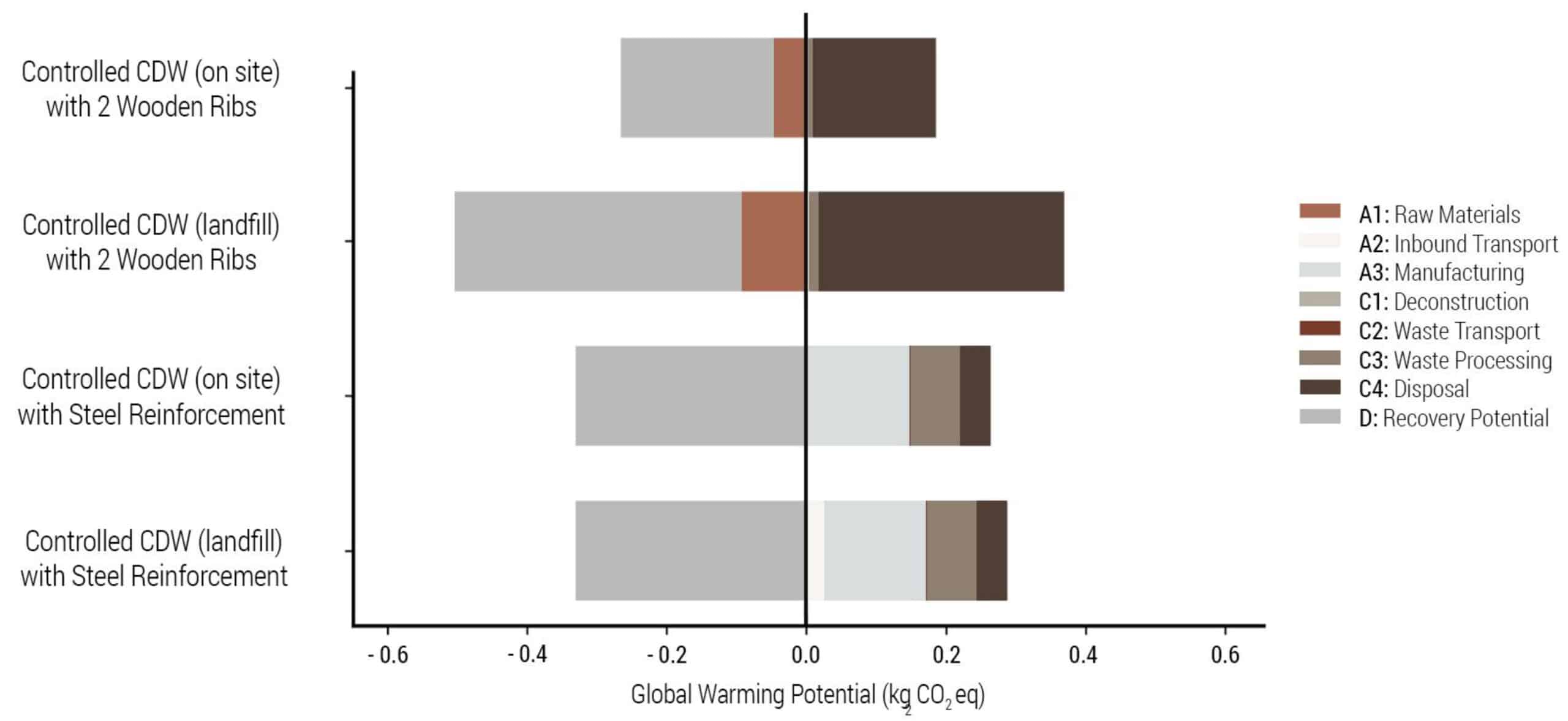
Steel and timber reinforcement systems were compared, revealing timber to have the lowest carbon footprint while reused steel remained a competitive low-impact alternative.
Principles of a Spanning Element
Differential Stress Distribution Across the Structure
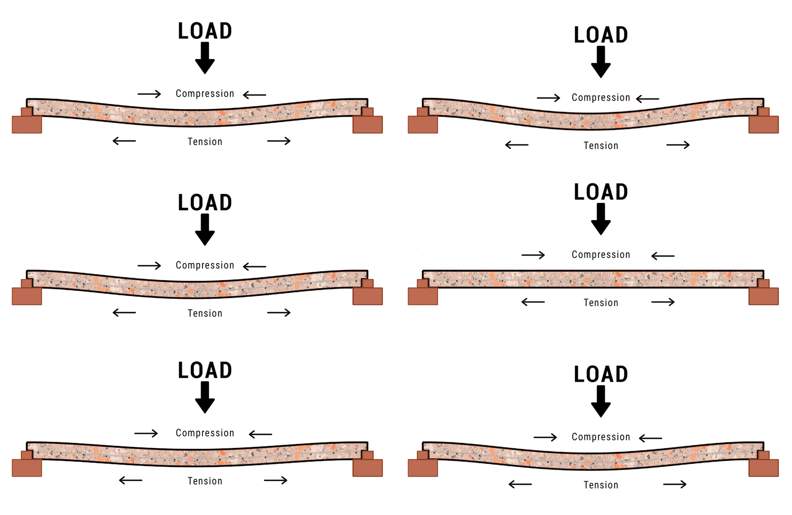
Structural behavior was first examined by considering the compression zone at the top of the slab and the tension zone at the bottom.
Maximum Compressive Stress
Evaluating the Global Warming Potential of On-Site vs. Landfill CDW Processing
Structural Performance Analysis
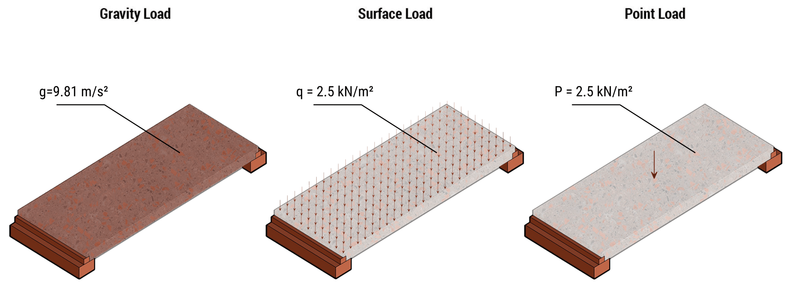
Load Conditions Applied to the Prototype
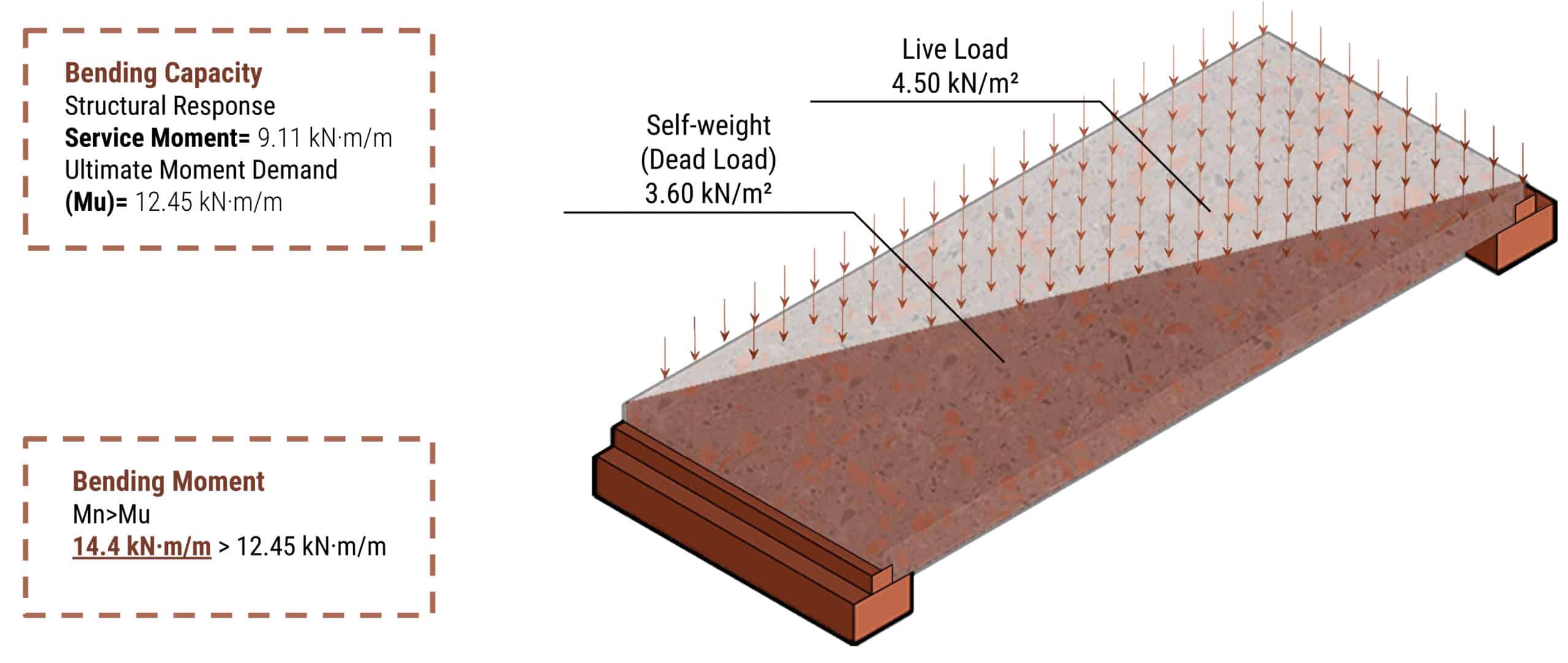
The slab was evaluated under self-weight, distributed surface loading, and concentrated point loading to represent its primary service conditions.
Optimizing Internal Reinforcement
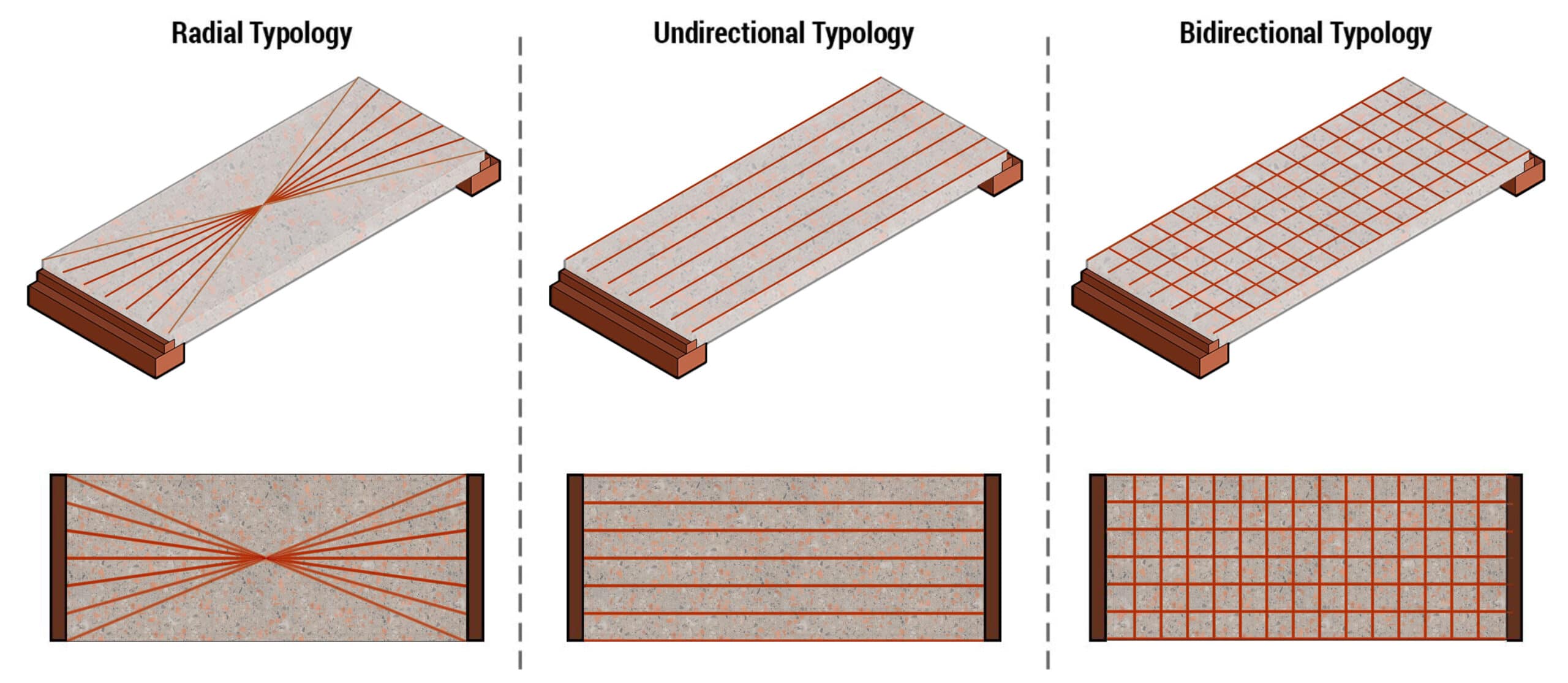
Line-to-Beam Analysis Identifies the Grid
Multiple reinforcement layouts were analyzed to determine the most efficient load transfer mechanisms.
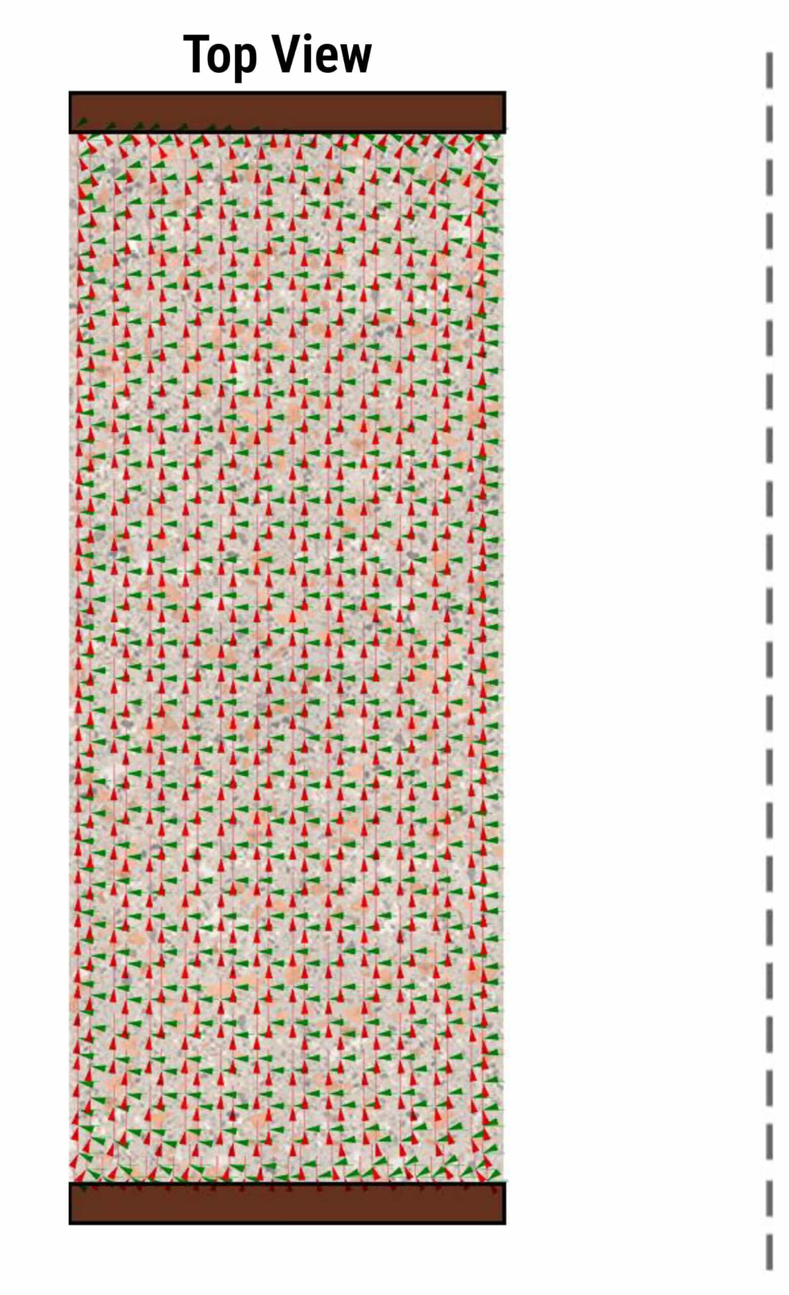
Principal Stress Analysis
Stress Distribution across the Slab
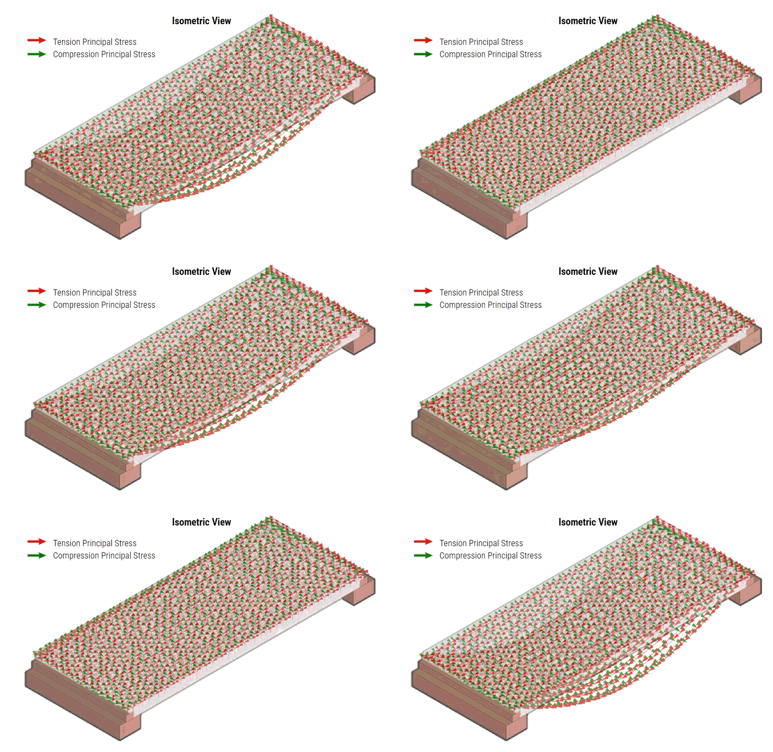
Principal stress analysis identified the compression and tension regions, thereby defining the required reinforcement zones.
Displacement Analysis
Deflection under Applied Load
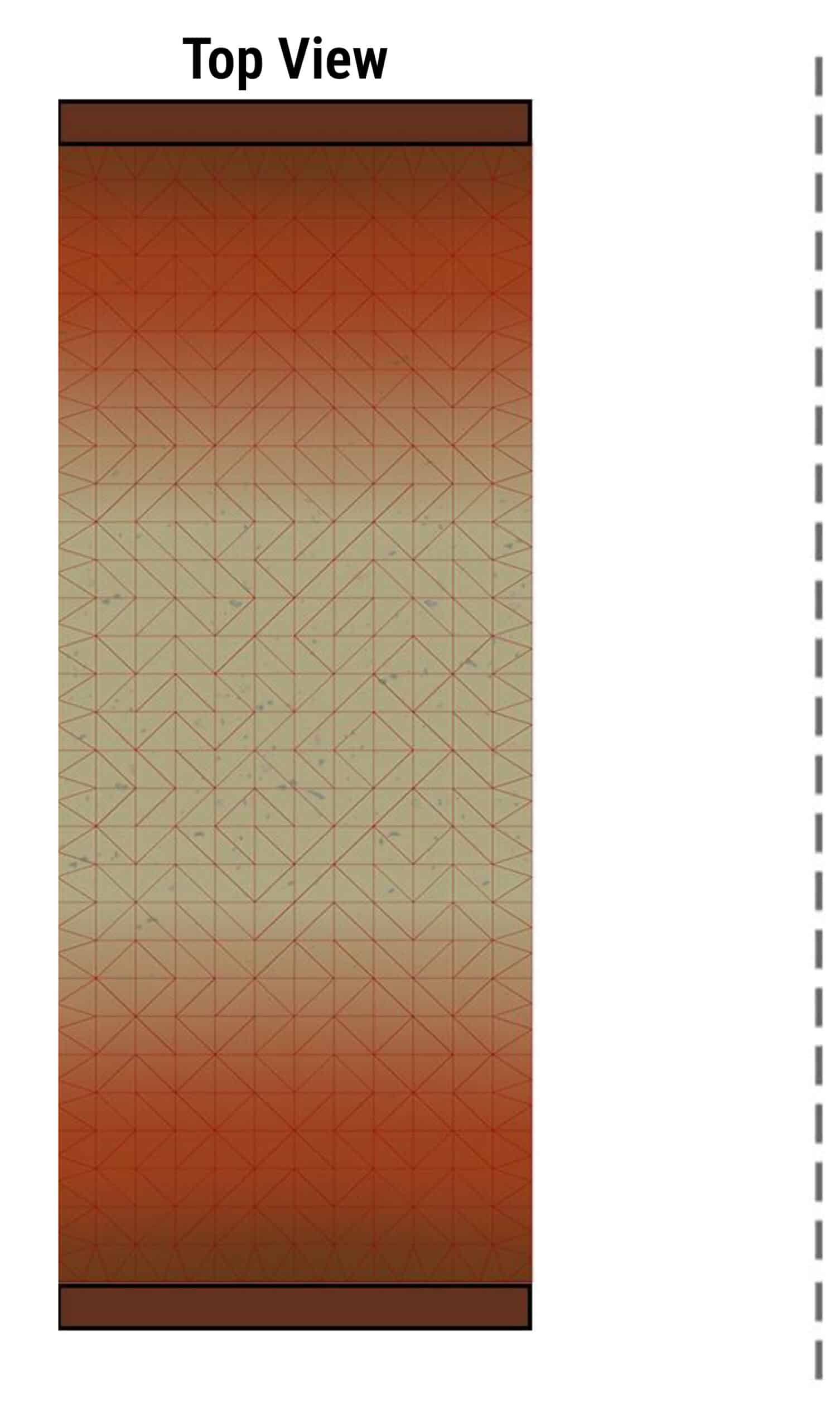
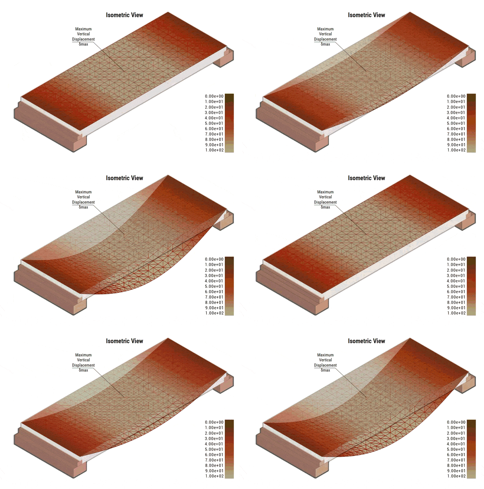
Displacement analysis confirmed that maximum deflection occurred at mid-span, consistent with structural expectations.
Flexural Performance Analysis
Calculation of Reinforcement for the Prefabricated Slab
The required reinforcement for the prototype was calculated using the experimentally determined material properties.
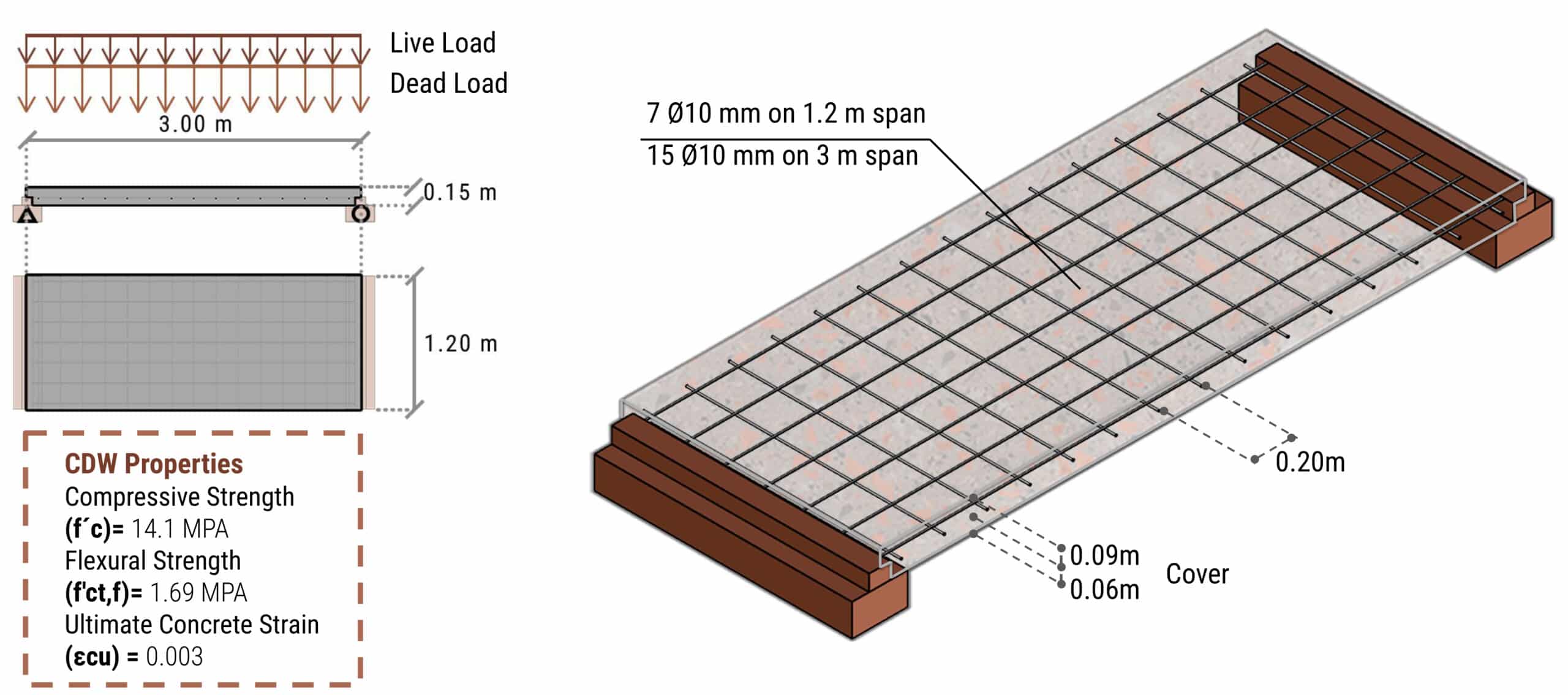
Structural verification confirmed that the slab capacity exceeded the required bending resistance, demonstrating the feasibility of the proposed system.
Next Steps
The research subsequently expanded beyond the material and prototype scale to investigate the broader implementation of a circular construction ecosystem.

Scaling the System
Industrial Scalability
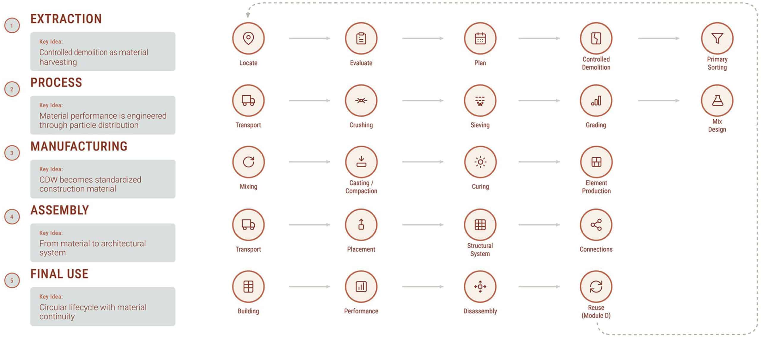
The scalability diagram illustrates a non-linear circular workflow in which components are designed for future disassembly and reintegration into the construction cycle.
Data Informed Sourcing
Urban Mining Interface and Building Analysis Diagram
An urban-scale digital interface was developed to reimagine the city as a searchable material database using publicly available municipal data.
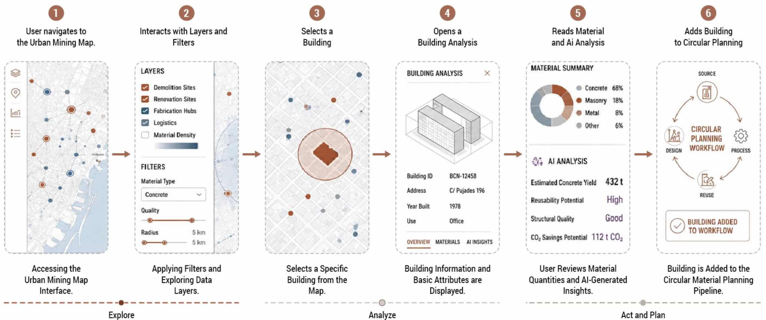
The platform demonstrates how multiple urban data layers, such as demolition sites, renovation projects, fabrication hubs, logistics networks, and material density maps, can be integrated. Building-specific analyses generate material quantities, structural information, reuse potential, expected concrete recovery, and carbon savings, enabling buildings to be identified proactively as future material banks.
User Interface
System Design
Proposal A
A centralized production model is proposed in which materials are recovered through controlled demolition, transported to a central processing facility, transformed into recycled concrete, prefabricated into structural elements, and returned to the construction site for assembly into buildings designed for future disassembly
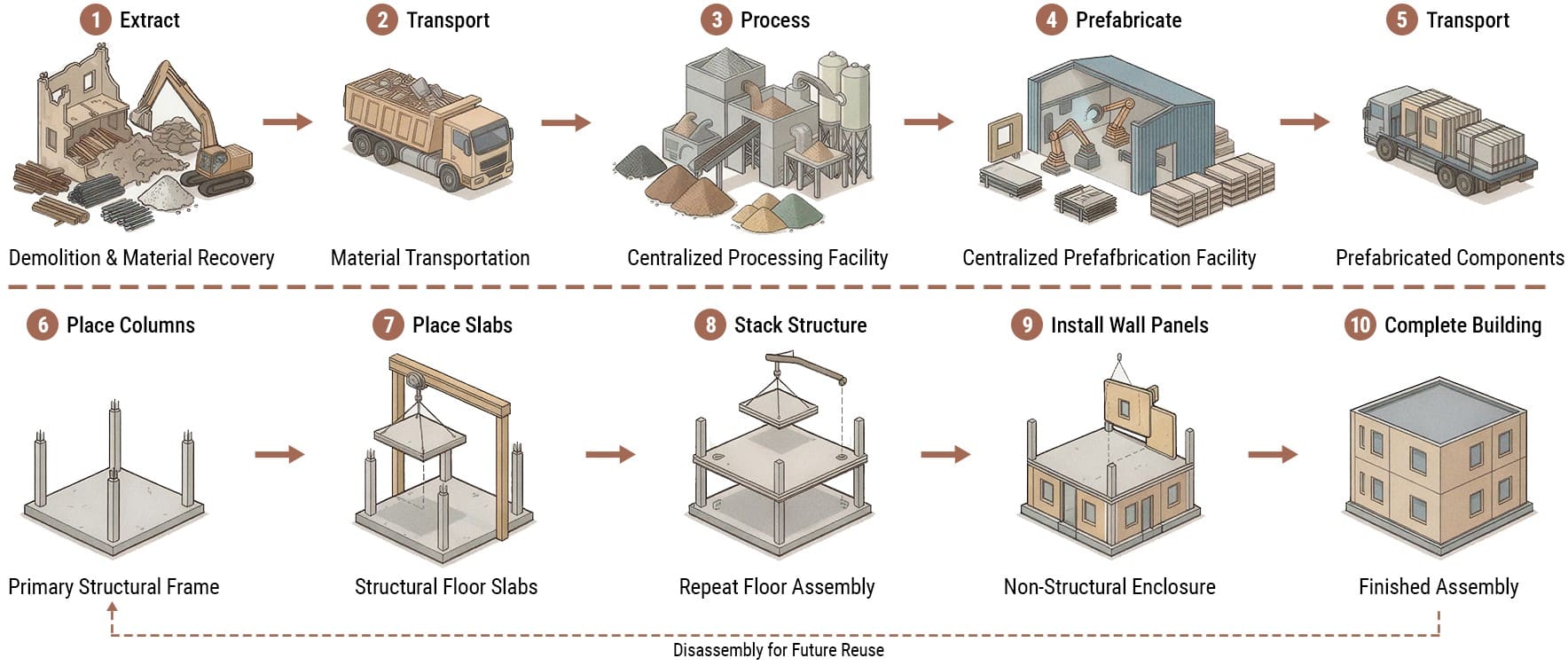
The centralized workflow begins with the identification of suitable material resources through the urban mining platform. Buildings are selected based on material inventories and reuse potential before undergoing documentation, controlled demolition, material separation, transportation, processing, aggregate engineering, robotic slab fabrication, curing, and final transportation back to the construction site for assembly.

Proposal B
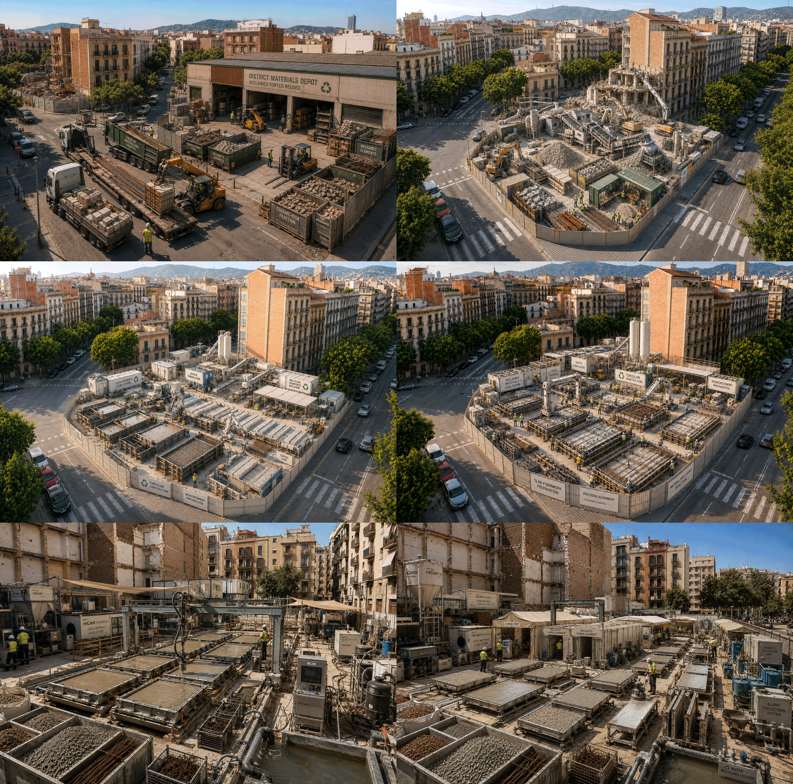
A second proposal investigates a distributed on-site circular construction model, in which demolition sites function as temporary fabrication facilities. Materials are processed, fabricated, and reincorporated directly on-site, significantly reducing transportation while shortening the material loop.
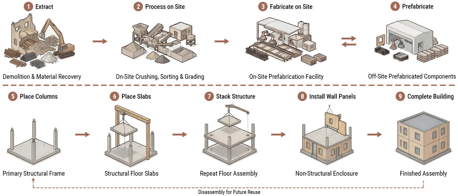
By transforming demolition waste into structural building components, ReCast demonstrates how localized circular material networks can contribute to rebuilding cities through a more sustainable and resource-efficient construction ecosystem.
Final Video
