
RE:EDU aims to reinstate the schools in Ukraine which were heavily damaged during the invasion by russia. It suggests a temporary relocation system which can accommodate the students while the schools will be rebuilt for the next 2-5 years.

Design
The design approach is modular by discretizing typical school typologies in a smaller raster and packing it in a chunk of 15 by 15 meters. In this way school parts are aggregated to create a temporary school.
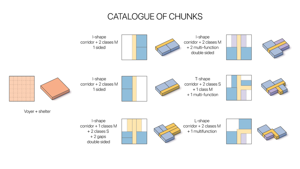
The advantage of modularity of the system is that it can adapt and fit to any site across the country, ranging from a small size in the village up to a bigger one in the cities. The system takes into account the shape of the site.

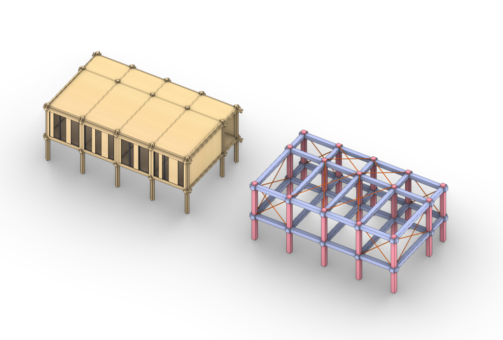
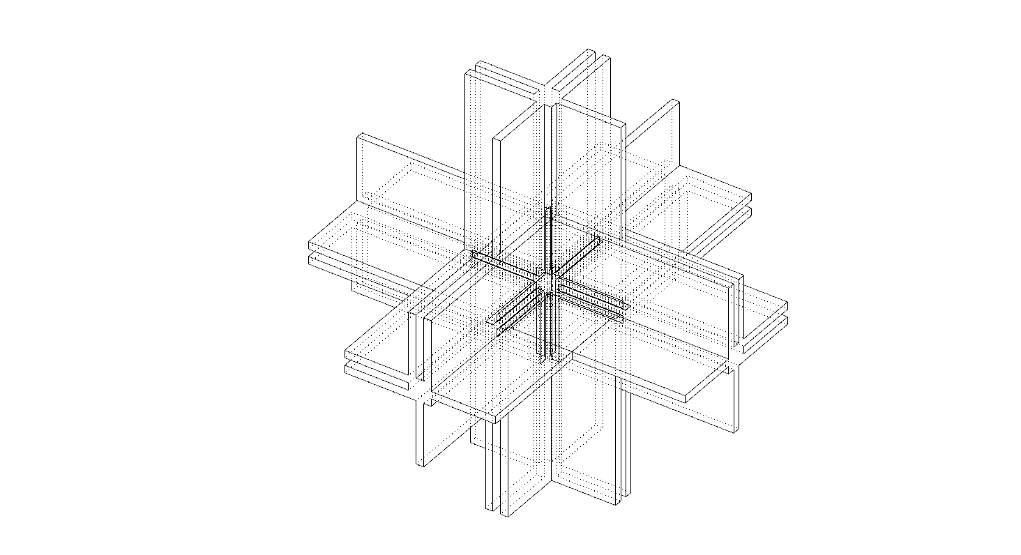
The structure is converted to the FE Model as beams, columns and bracings and simplified for the analysis. The actual cross section is a cross, simplified it into square section, The actual situation of structure is elevated from the ground by small vertical elements and joints are special elements combining wood and steel plates to stiffen intersection which are not placed in the model
Structure

Loads

Modules
The program and the division of the units are different and the structure is designed for each unit accordingly. Every module has axis for columns and beams, so that after the space program is aggregated, a structure can be placed inside. The structural raster has a step of 1,25m. Typical spans are 2,50m for the corridor and 6,25m for the class.

Optimization
For the optimization process the selection of different cross sections of Beams, the Size and the Location of Bracings are investigated. The smallest cross section was applied to columns in the optimization process.The analysis purpose is to use the least amount of structural material that is possible to lower the construction costs.The aggregation starts from the core component and while adding elements to the aggregation the monitored values can be seen for structural performance check. The results of the aggregation finally fall into structural requirements but, using the same cross section for all elements, the system is using far more material than necessary, therefore the result is not efficient.The first solution is to experiment with cross section optimization. Starting from a very slender section of 15 cm, the variety of sections utilized in this scenario overcomplicates the system composition. 20 cm has an overall balanced optimization, utilizing 3 cross sections but from this point the overall mass starts increasing again. The optimization continues here with 25 showing very good structural performance but relies on several 30 cm section beams. When the system reaches 30 it is back to the same cross section element and initial condition before the optimization. A better approach was to implement the system with steel rods to achieve stiffness with less structural material. In this case, the result overall of the cross section optimization from the 15 cm section, with the addition of bracing elements from the 0% ratio to 100%, fully braced system. Generally, for every case that the bracing doesn’t do much for the structure after 20-30% reduction rate but you can see the system overall weight is lighter when reinforced with rods keeping the cross section at 25 cm.
To conclude, this combination is selected as the best solution for the structure of this system. The system has the same cross section of 25×25 cm and 39 steel braces distributed in the structure to respond mainly to wind stresses. Using the same element is best for simpler assembly and bracing arrangement can secure the structural stability.

The overall final result compared with the amount of CO2 from the first resolution up until the optimization. The calculation is made manually knowing the amount of CO2 emissions of the used materials. In the first situation, the mass of columns and beams are extracted and multiplied by the CO2 emission of timber. Following slabs, walls and facade are calculated for CLT material. In the last situation in addition to the former calculations steel bracing CO2 emission is added. The massing amount is halved after the cross section optimization on beams and columns and addition of bracings. As a result, The CO2 emission is almost cut to half as well.

