In this workshop we explored computation design and fabrication through the study of stereotomic geometries. Our task was to create a stereotomic voussoir – which is a single element in an arch or vault – whose logic could be decoded so that it could be built in grasshopper and then be replicated across the surface of a global geometry. At the same time, we learned how to take this series of voussoirs, which were defined as closed breps in grasshopper, and process them using another grasshopper script to produce instructions for the ABB robots. Finally, as an iterative process we fabricated our voussoirs out of styrofoam, developing along the way some intuition about the challenges and opportunities presented by stereotomic fabrication. In this post we will explain the creation process of our final geometry.
Geometries
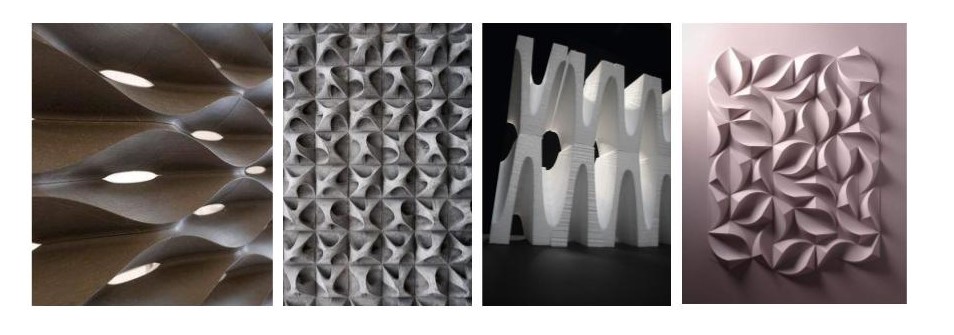
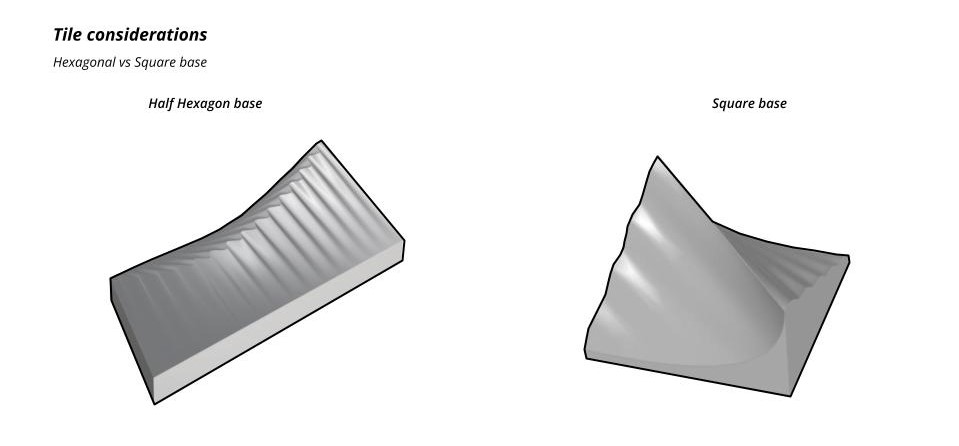
According to the inspration images moodboard, we came up to two tile considerations: hexagon and square base. The designs which are shown below consist on parametric designs which allows the modification of their curves frequency , height and curvatures. Both designs are shown at the image below:
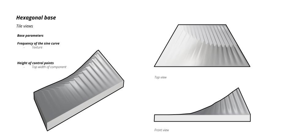
Component 1
First, we started explaining the half-hexagon base design. This tile parameters include the frequency of the sine curve (which its texture changed depending on this) an the height of the sine curve control points (which decided the tiles height)
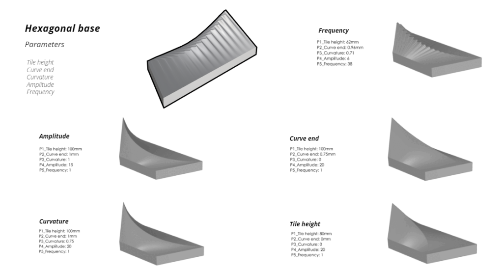
This tiles evolution was then discretized to 5 main parameters: tile height, curve end, curvature, amplitude and frequency. Each of these parameters consist on a minimum change that varies from 0mm to 100mm.
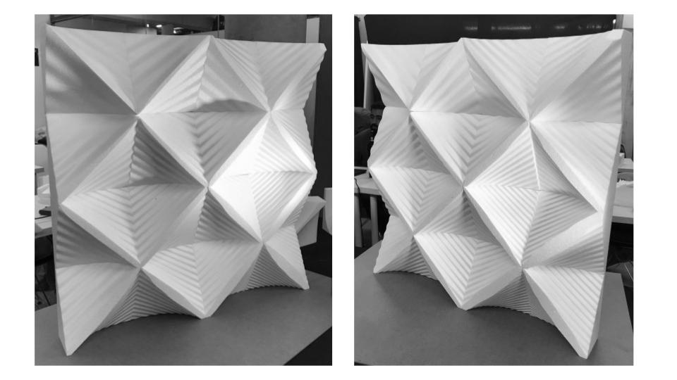
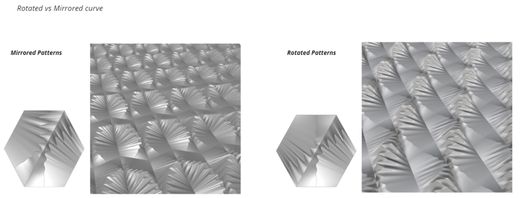
Once we had the geometry, we could arrange the tiles either mirrored or rotated. Depending on the assemblage, the result would be totally different using the same tile. With this we created a pattern and finally generated a wall simulation to see a final scaled result.
Component 2
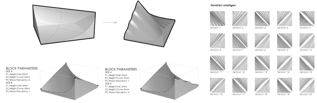
For the second geometry, we created a square-based tile comprehended by 2 cuts (2 sides) and 2 main parameters on each one: height line and height curve. These values vary from 0 to 50mm and the top cut is affected depending on them. The higher the value, the more covered-area from the top of the component.
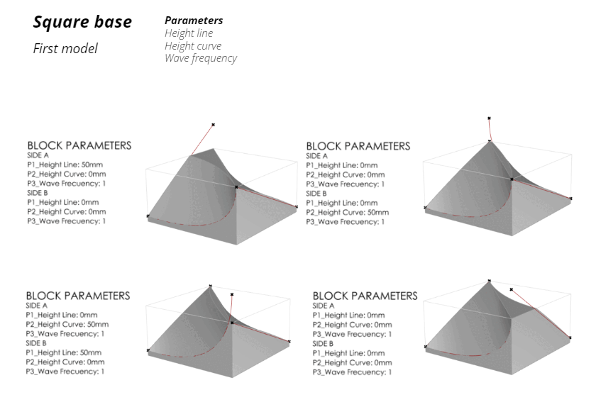
After generating the first model, we decided to add one more parameter which could generate a more-texturized tile: wave frequency. This third parameter was implemented on the straight cuts from the blocks and caused a wavy-like side. With this final change, we created 20 iterations that were changed parametically with the values mentioned before so that afterwards we could propose a surface wall.