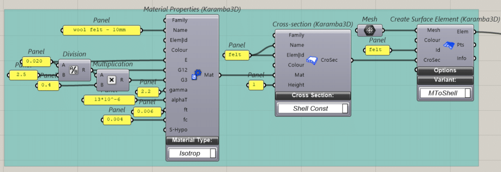
When you’re building with a material that has no entry in a standard structural materials library, the first job isn’t drawing a frame, it’s defining what the material actually is. That was the starting point for the structural phase of our robotic needle-felted wool prototype: before we could ask Karamba to tell us anything useful about how our piece would behave, we had to set up the felt itself as a bespoke material. We pulled material property values from existing material research on wool felt and then adapted them to our own panel (our specific thickness, and fiber density) rather than relying on a generic, off-the-shelf material definition. Everything that follows, every deflection curve and utilization ratio, sits on top of that calibration.
The Frame
Starting Big, Then Cutting Back
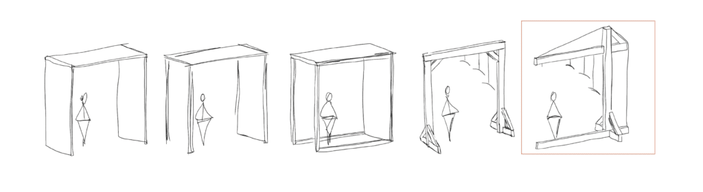
Our first structural concept approached the frame like a section of the room our system might one day be installed in – a full timber frame with a rigid ceiling and wall support holding the form.
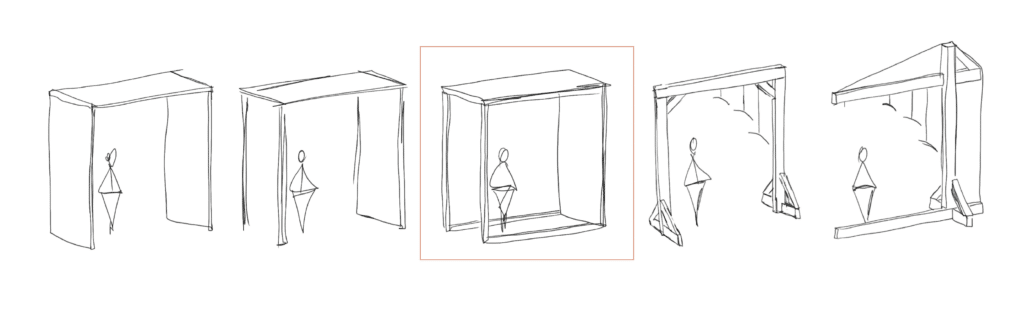
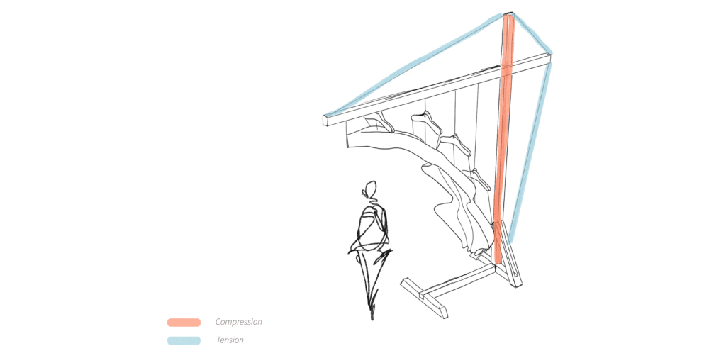
It quickly became obvious that this was structural overkill for a material this light, and it worked against one of our core requirements: the installation needed to be moveable. So we simplified. Version 2 reduced the frame to a single column with a cantilevered top, with a tension cable across the upper span doing the work that a second vertical column would otherwise have had to do. That one change accomplished two things at once; it cut the footprint dramatically, and it kept the viewer’s sightline to the felt panel completely unobstructed.
Setting up the model
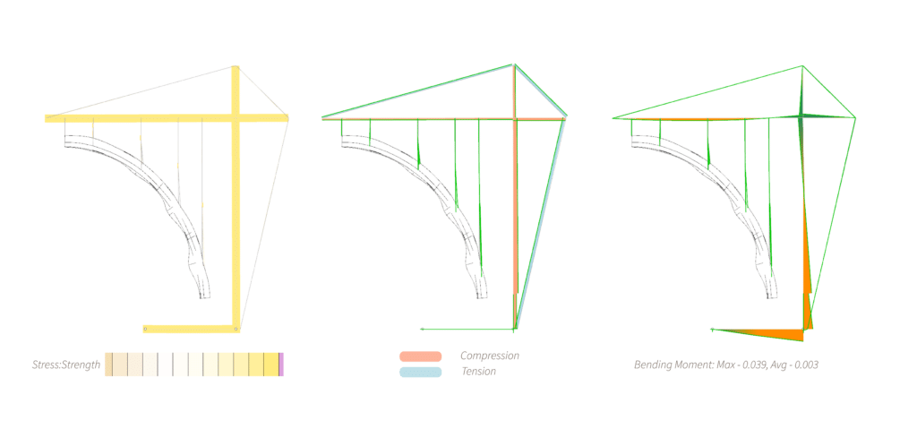
In Karamba, we modeled the felt as a surface mesh, the timber members and steel rope as linear elements, with gravity (self-weight) as the applied load case and the base points fixed as supports. From there we ran the frame through a series of cross-section tests. A generous 10 × 20 cm timber section returned vanishingly small utilization numbers (max 0.021, average 0.008), telling us we had far more material than the loads demanded.
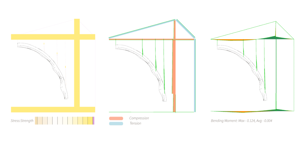
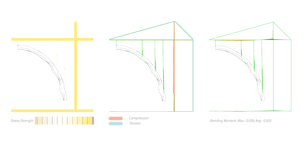
Dropping down to a 4.7 × 10 cm section still kept utilization comfortably low (max 0.053, average 0.021), confirming we had real room to lighten the structure without compromising it.
From observer to inhabitant
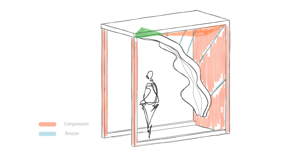
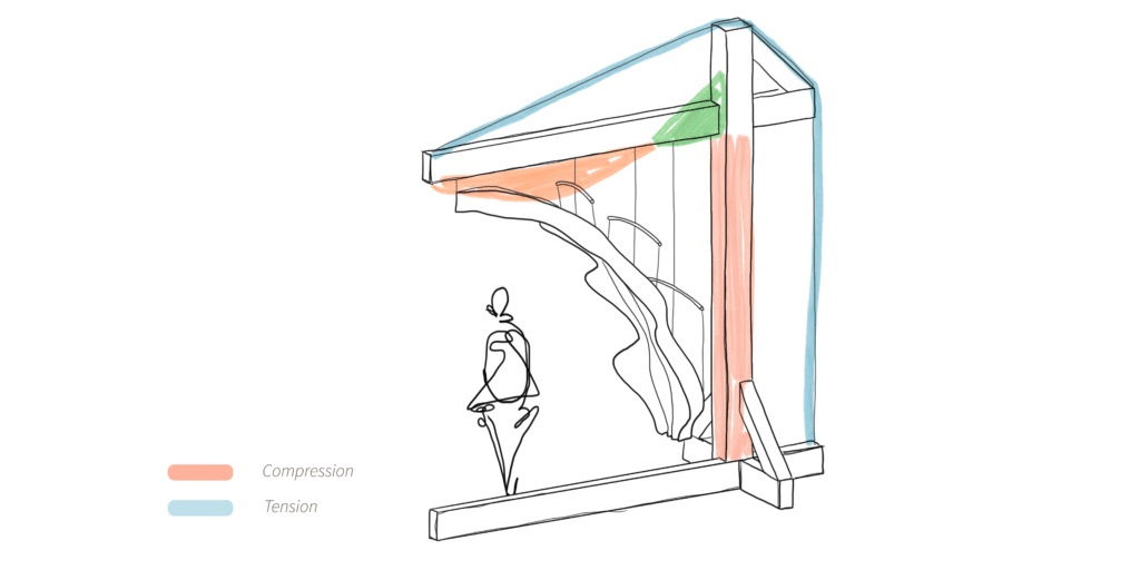
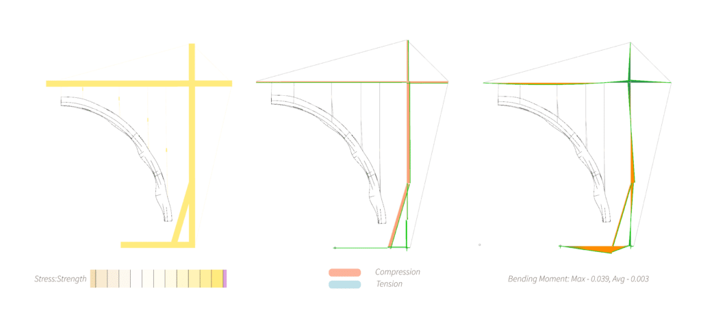
Version 3 pushed the spatial idea further: we opened up the base of the frame by removing the front ground member entirely, letting a viewer step inside and stand beneath the hanging felt form rather than just look at it from outside.
Removing that ground member also changed the structural picture, concentrating more demand on the remaining vertical support, so Version 3.1 added a diagonal brace at the base to recover stability.
That stability question turned out to matter more than we expected. When we ran reaction forces under self-weight alone, the numbers were small and unremarkable; 0.10 to 0.14 kN. But once we applied a horizontal load of 200 N, representing nothing more dramatic than someone accidentally bumping the piece, the reaction forces jumped to ±0.23 kN, and the analysis flagged a real risk of the frame tipping over.
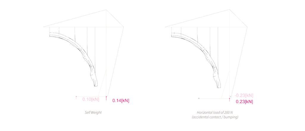
That single test reshaped our next steps: either widen the base footprint or add 25–30 kg of ballast at the base of the main vertical member to keep the installation safely planted under everyday gallery conditions.
Exploring Felt Geometry
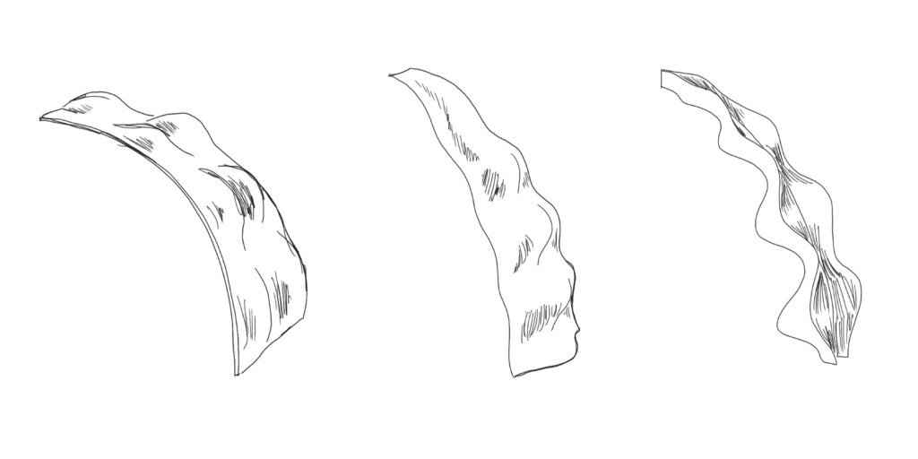
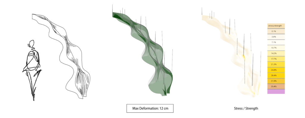
In parallel with the framework, we explored how the geometry of the felt panel itself affected its structural performance. We tested three variations: a broad, gently curved sweep; a narrower wave with more pronounced undulation; and a tighter sinusoidal form with repeating folds along its length.
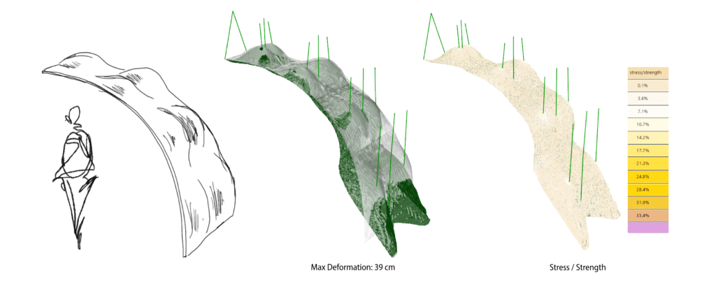
Each one was set up as a surface mesh and analyzed for deformation under its own self-weight. The differences were not subtle. The first form deformed noticeably under load, 39 cm distributed across the form.
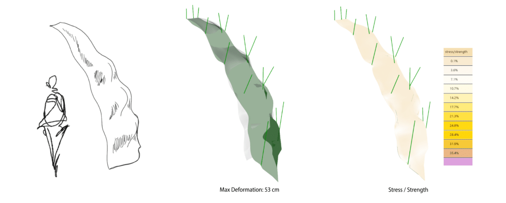
The second wave held up even less, deforming a total of 53 cm.
The sinusoidal form outperformed both by a wide margin, maintaining its geometry significantly better than either alternative, though the analysis did surface one localized weak point: deformation concentrated in the upper section of the panel where it met the hangers.
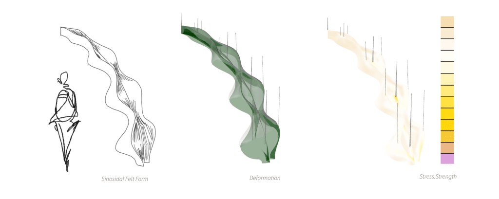
The fix was simple. Rather than redesigning the geometry, we added one small additional hanger near the top to distribute that load across more points along the panel’s length. Re-running the analysis with the extra hanger in place showed deformation spreading evenly across the whole form, with the upper section’s movement reduced substantially and the stress-to-strength ratio sitting comfortably within acceptable limits everywhere along the panel. That configuration became our resolved geometry.
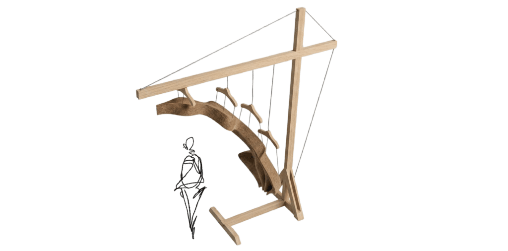
Where the design landed
The current iteration combines a three-layer laminated timber cantilever frame, with a 6 × 10 cm cross section, four wooden hangers at 3 cm thickness, a 2 × 2 cm aluminum track, and 2 mm steel rope, all calibrated against a felt panel whose material behavior we’d defined ourselves from the ground up. Looking ahead, two threads carry forward from here: continuing to develop felt forms that build on the sinusoidal logic that performed so well under self-weight, and resolving the tipping risk at the frame’s base, either by widening the footprint or adding ballast, so the final prototype can stand confidently under real-world handling, not just under a static load case.