Concept
Creating a circuit based on operating principle of distance detection and on the usage and applications of ultrasonic sensors in PAS (parking assist) applications.
Workflow
Using an ultrasonic sensor as in input which measures the distance to obstacles (walls, etc.) and reports their proximity to the driver.
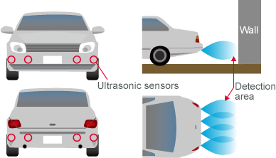
PAS basic operation
Pulse signals are transmitted, the ultrasonic waves reflect off of obstacles, and the distance to the obstacles is measured based on the time until the reflected waves are received.
A clock pulse is generated when each pulse signal is transmitted, and this clock is used to measure the time.
Reflection time (s) × speed of sound (340 m/s) = distance to obstacle (round trip)

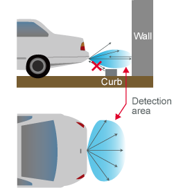
Characteristics necessary for PAS
– Must be able to detect a wall behind the vehicle while ignoring the curb.
– Each sensor must cover a wide range to reduce the total number of sensors required.
– Must be able to detect very close proximity.
Therefore, sensors with the following features are desirable:
Directionality that is narrow vertically but wide horizontally
Short resonance time
BOM (Bill of Materials)
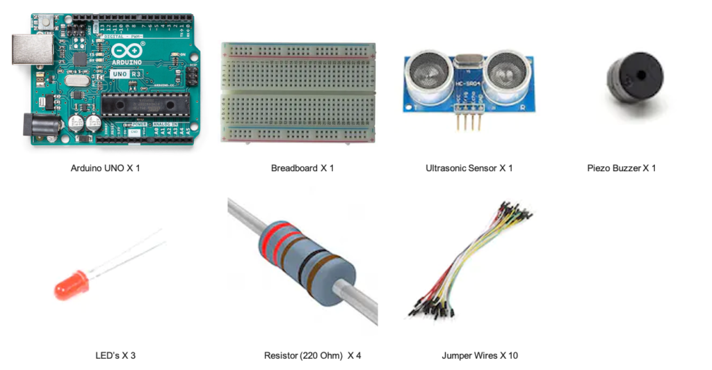
Step 1: Assemble the Components
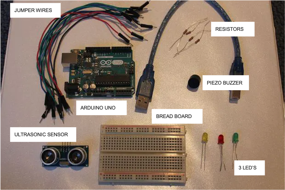
Step 2 : Setting up the Components
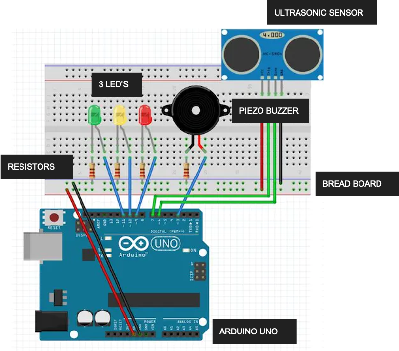
Step 3 : Assembly- Breadboard
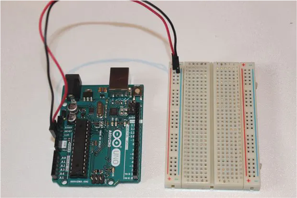
? Connecting a wire from the 5V pin on the Arduino to the positive channel of the breadboard.
? Connect a wire from the GND pin on the Arduino to the negative channel of the breadboard.
Step 4 : Assembly- Ultrasonic Sensor
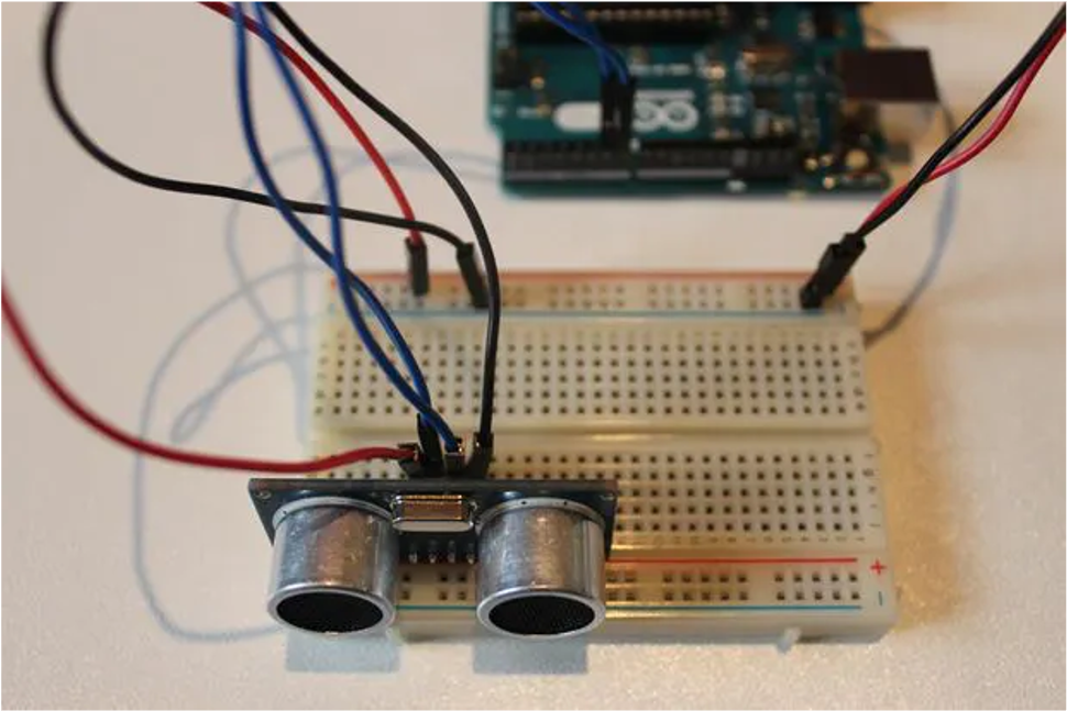
? Connect the GND pin on the ultrasonic sensor to the negative channel on the breadboard.
? Next connect the Trig pin on the sensor to pin 2 on the Arduino.
? Connect the Echo pin on the sensor to pin 3 on the Arduino. Lastly, connect the VCC pin on the ultrasonic sensor to the positive channel on the breadboard
Step 4 : Assembly- LED’s
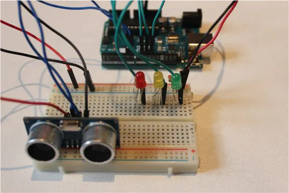
? Attaching all the LED’s on the breadboard
? Connecting Resistors on the Cathode (shorter leg) of the LED’s and the GRND of arduino.
? Connecting the Anodes (Longer leg) to the digital pins i.e. 9, 10, 11.
Step 4 : Assembly- Piezo Buzzer
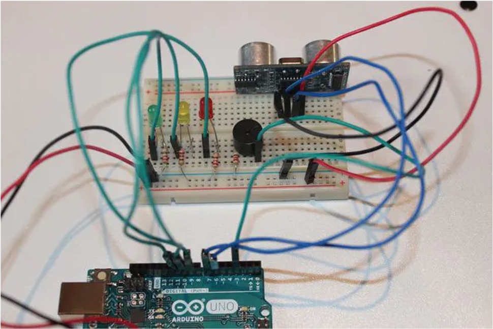
? Connect the longer leg of the buzzer to pin 7 of the Arduino.
? Connect the shorter leg of the buzzer to the negative channel of the breadboard using a 220 ohm resistor.
CODE