
General presentation of the research
Knowing that the printed geometries require a drying time that forces to limit the daily printed layers, thus slowing the construction process and increasing the financial cost, the aim of this research was to find a system that would increase the drying time and then faster the process.
The research conducted by Jose Antonio Gutierrez Rangel, Mark Francis and Noel Akroma focused on the ventilation and the dehumidification of the printed wall.
This strategy, essentially based on previous studies and physical principles such as the venturi effect and the stack effect, the research explores the wind as a tool to ensure a homogeneous drying inside the walls.
To research our goal, we first observe what the previous research inside and outside of 3dpa allowed us to deepen or not. From this point, we went to the next step, which was to develop geometries based on the Kib²aha (Hassell prototype) and analyze their behavior in the drying period.
1. State of the art
It was difficult to find a starting point for this research. It was so important to know what had been done and which direction. This little documentation oriented us to 2 essential principles of the fluid dynamics which are the Venturi effect and the stack effects.
a. Outside an inside 3Dpa
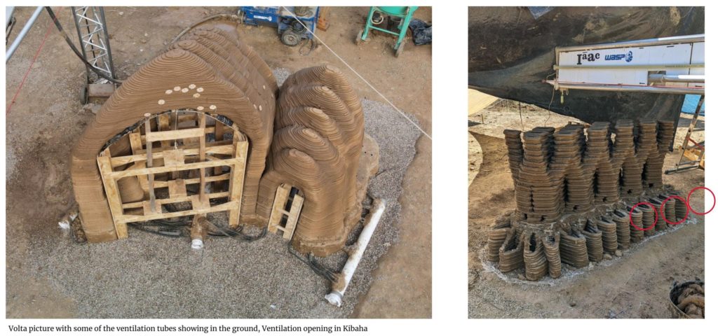
Inside 3Dpa, if the previous projects achieved were not focused on this thematic, they still tried to fix the issue of the disunification by an active ventilation system. Grounded pipes connected together to a tube and a fan were used in TOVA and VOLTA to try to extract or push the air inside the infills.
Outside the program, several tests highlighted the possibility to use the air flow to cool an inner space. If those researches are essentially focused on the interior comfort and use ceramic as material, it’s still interesting to see how we could reuse the power of the wind for our own project.
b. Venturi and Stack effect
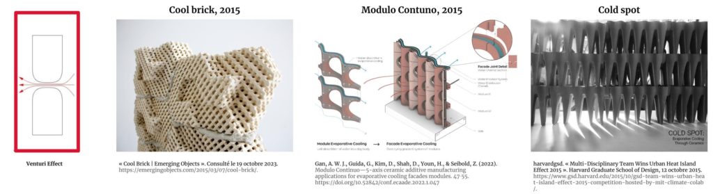
The reuse that can be done lay on two scientific effect which are: the venturi and the chimney effect:
The first effect can be defined as the reduction in fluid pressure that occurs when a fluid flows through a narrowed (or constricted) section of a pipe. The the effect suggests that in a continuous flow of incompressible material, the pressure reduction at a specific location will accelerate the material’s velocity at the exit of the depression
The second effect suggests that a thermal draft occurs when a temperature difference results in a difference in air density between the entry and exit of a duct, leading to an airflow. This effect is accentuated by a taller chimney.
Partial conclusion
This first overview is clear: venturi is the main effect used in the past and it is the one we will focus on. Because of the acceleration given by the cavities, the venturi ensures the possibility to increase the velocity of the wind and so ventilate an inner space. This observation can also be used to maximize the velocity of the wind coming in the wall to dry it faster. Linked with a chimney effect, we can’t imagine this fresh air traveling all along the geometry to cool it faster.
2. Develop different cavities strategies
From our understanding, the goal is now to know how to use the wind in a way to empower the drying time of the 3D printed geometry with a particular attention on the application to the Kibaha’s geometry. With digital exploration, we observed the behavior of the wind in a cavity before producing different geometry. Those geometries play on various positions of the cavity in order to see which one dries the structure the fastest.
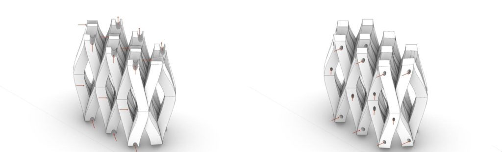
a. How to redirect the wind?
Regarding the previous understanding, we tried to simulate the airflow in funnels by using Grasshopper and the software Butterfly. We did 18 simulations, based on 4 scenarios.
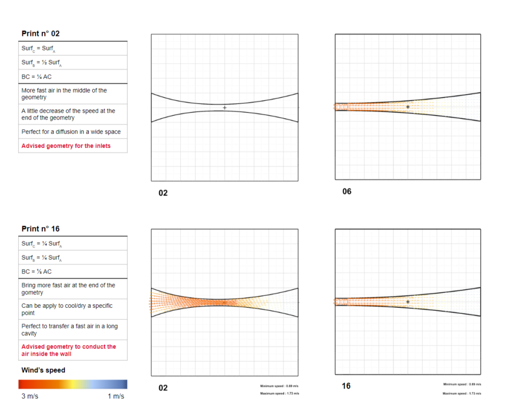
In scenario 1, the two openings (A and C) have the same size, the middle opening (B) is ½ of the opening and situated in the perfect middle of [AC].
In scenario 2, the two openings C and B are each ½ of the size of opening A, and B is still in the perfect middle of [AC].
In scenario 3, Opening B and A are equal and opening C is ½ size of opening A while B is situated in the middle of [AC].
In scenario 4, we tried the same disposals of the previous scenario, but with a ratio of ¼ instead of 1/2.
b. Tonak V1, V2, V3
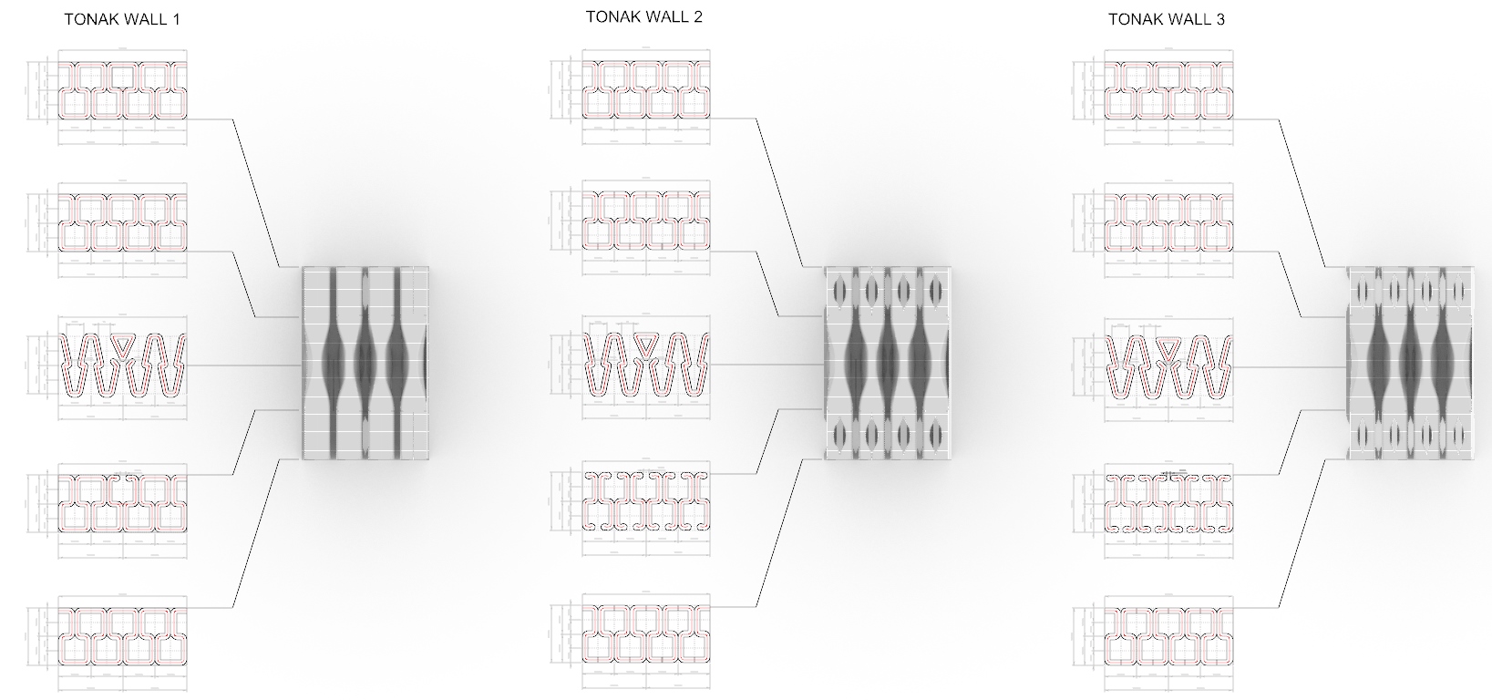
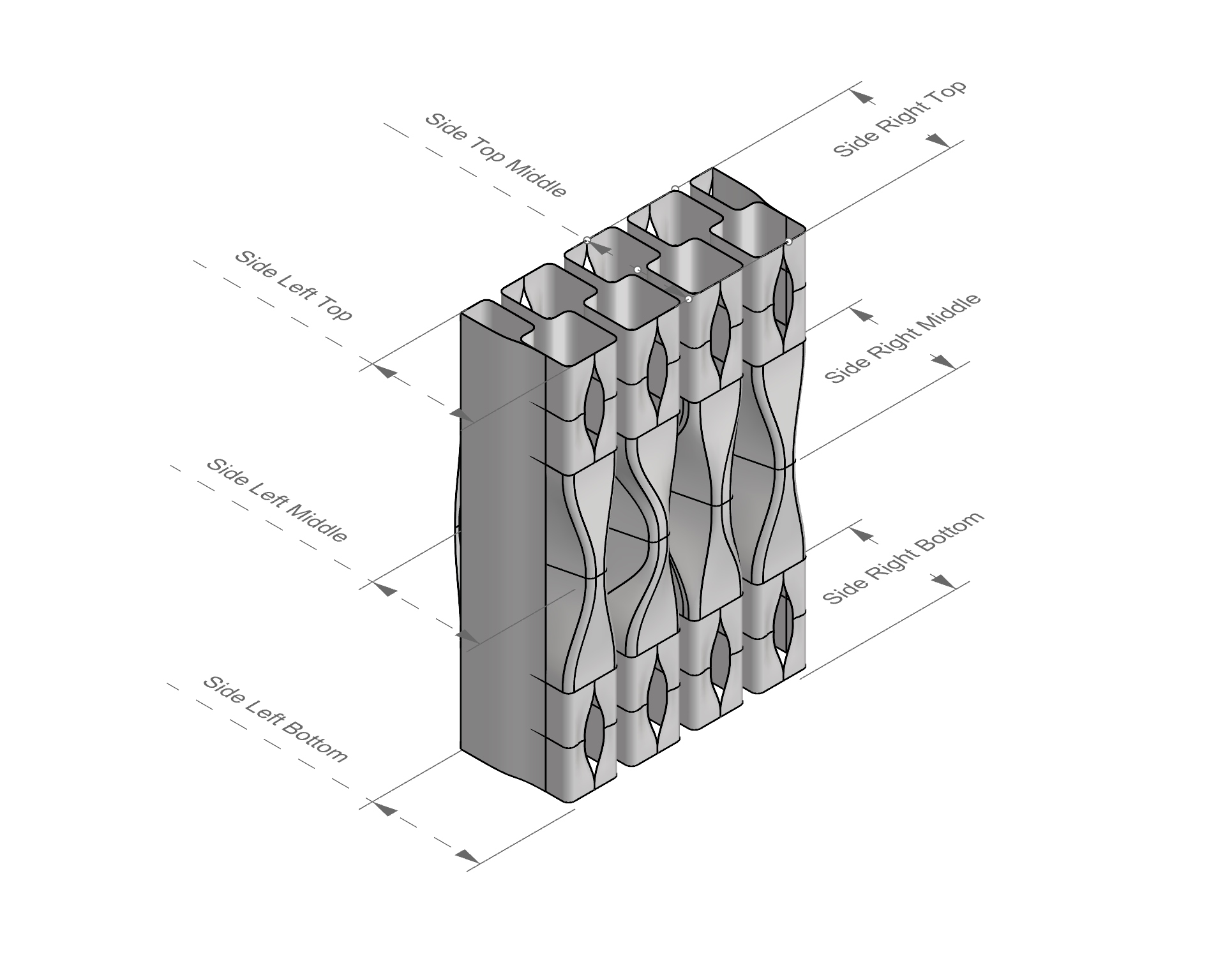
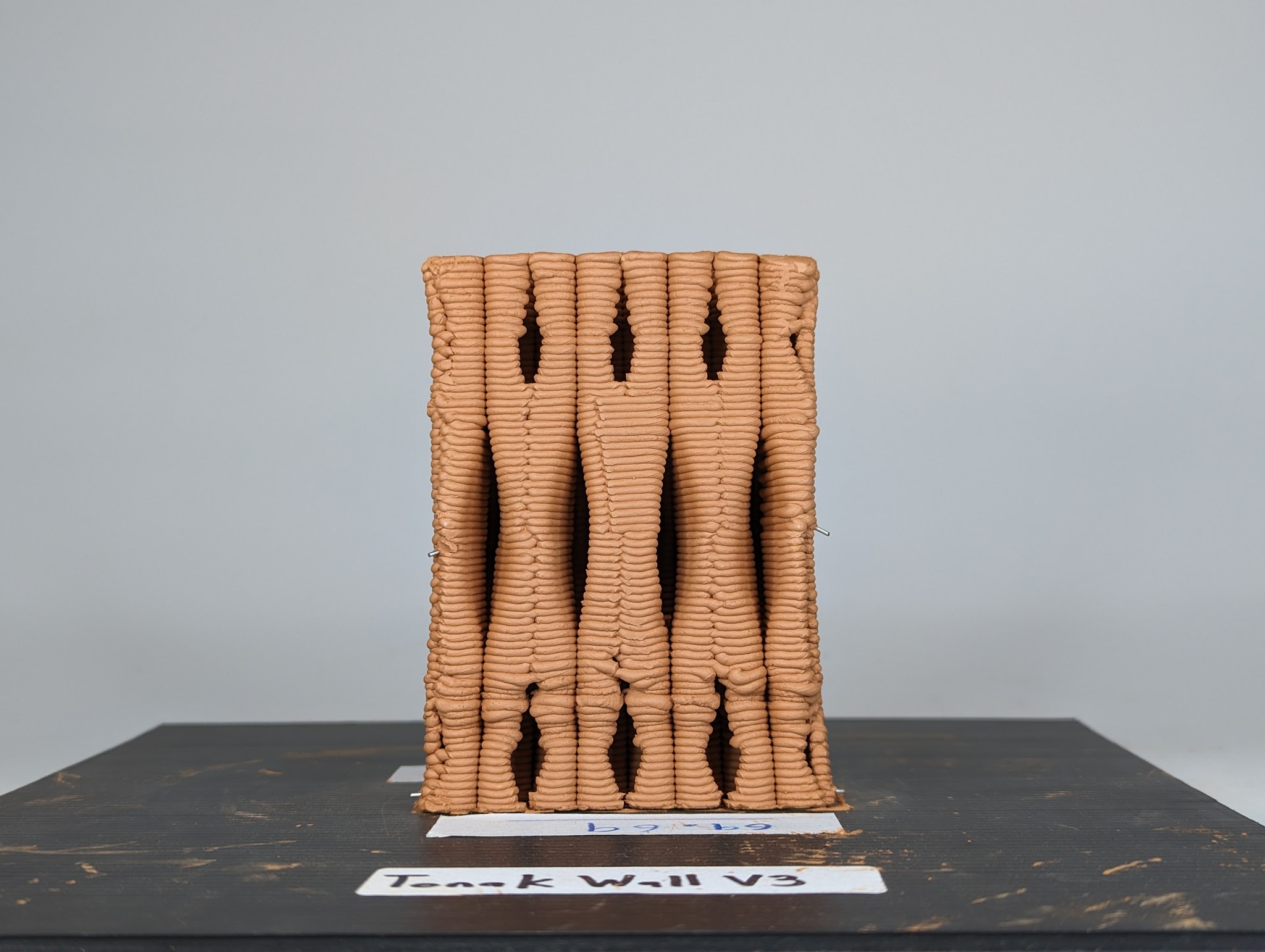
We then created 3 variants of closed geometry (the Tonak walls) with an infill that exposed all the walls directly to the wind. Those variants were created to observe which one dried the fastest regarding the different configurations. While drying, the clay evaporated water, which made him lighter with the time. TO measure how fast they dry, we weigh them continuously during their drying period.
Tonak 1, is an infill design to allow the walls to be directly exposed to the air, but without opening on the upper and below parts.
Tonak 2, based on Tonak 1, receives openings on top and at the bottom of the geometry.
Tonak 3, has the same configuration of Tonak 2, with the difference that its lower and higher openings are 1 mm smaller than Tonak 2.
Partial conclusion
Digital exploration helps us to identify two types of depth. One that is more suitable to conduct the wind and ventilate a particular spot, while the other one is more suitable to diffuse the wind while keeping a high velocity in the spreading.
The first one can be assimilated to a funnel and appear when: SurfC = ¼ SurfA, SurfB = ¼ SurfA, BC = ? AC. The second one occurs when: SurfC = SurfA, SurfB = ½ SurfA and BC = ¼ AC.
If the pattern shape given from this understanding is too sharp to be transferred into an infill for the wall, we could at least exploit the general principle observed in a pattern. The second pattern was designed to let all the walls be exposed as much as possible while playing on different openings to direct the airflow. We expected the walls with the most and biggest opening (Tonak 2) to dry faster and this is not what we observed. But what happened is that at the end of the test, the three walls had roughly the same mass loss regarding the original one. Tonak 1 lost 31.74% of its original weight, Tonak 2 lost 31.75% of its original weight and Tonak lost 3 32.63% of its original weight.
What we can say is that, due to the small scale of the test, it is very hard to make a statement and maybe, a higher scale would be more relevant. In fact, it is difficult at this scale to make a statement and it will be maybe better to try at a bigger scale.
But in general, if the introduction of the holes does not affect the structure, it can still be envisaged to introduce them in other geometries. Which is what we tried with the Kibaha structure.
3. Test the cavity in the drying period
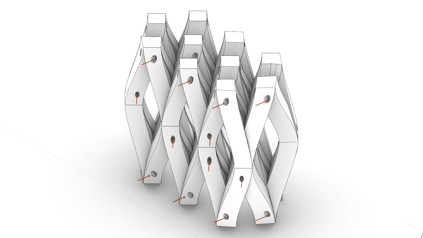
The last part of this test is to reproduce the same test with the Kibaha’s geometry to find a way to dry it faster and facilitate our construction process. To do so, we inserted holes in the geometry of Kibaha to observe the drying time. To have better accuracy, we augmented the size of the tested model.
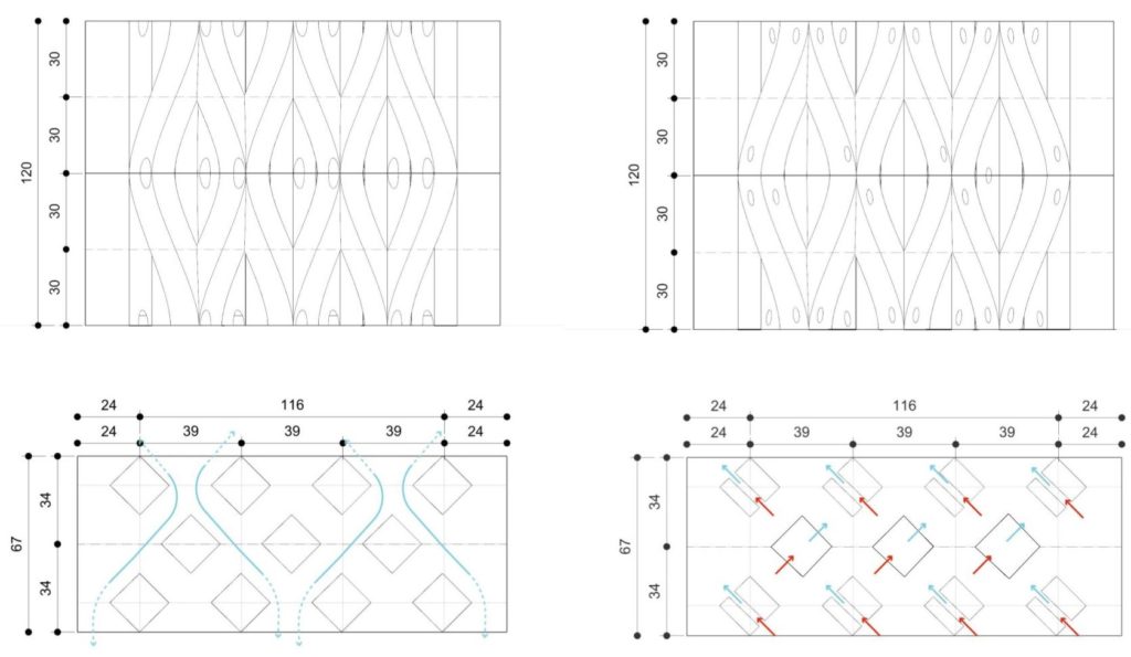
For this last test, we built 3 models based on Kibaha’s geometry. The two first are similar, without openings, but with 2 different conditions of drying. One dry without and second with continuous airflow. The third one has openings on it and dries also with a continuous airflow.
Rescaled, the goal is to observe if the presence of the micro-openings will affect the geometry. We can analyze the effect of the continuous airflows, as much as the effect of the openings.
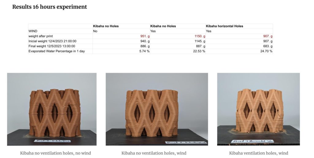
The measurement method is the same as the previous one. The only difference is that we could only measure the samples after one day.
Partial conclusion
After one day of drying, we can observe that the insertion of holes is relevant in the sense that it increases the evaporation of the water. While the original Kibaha geometry lost 22.87% of the weight of its original weight, the implemented one lost 2.17 point of percentage more.
General conclusion
The intention of this research is to contribute to the broader research effort that is improving the process and qualities of 3d printing earthen architecture.
Because fluid dynamics is a very difficult element to measure and analyze, the first understanding of this research is that the bigger the model is, the more accurate the result will be.
Also, if the use of the stack and venturi effect are very relevant and are worth to deepen, the only use of micro perforation in the geometry seems to help them to dry faster thanks to the expositions of the inner walls to the wind.
Those micro perforation, if done in a right way can improve the printing process without damaging the structure, which is an encouraging path to explore for further research.
