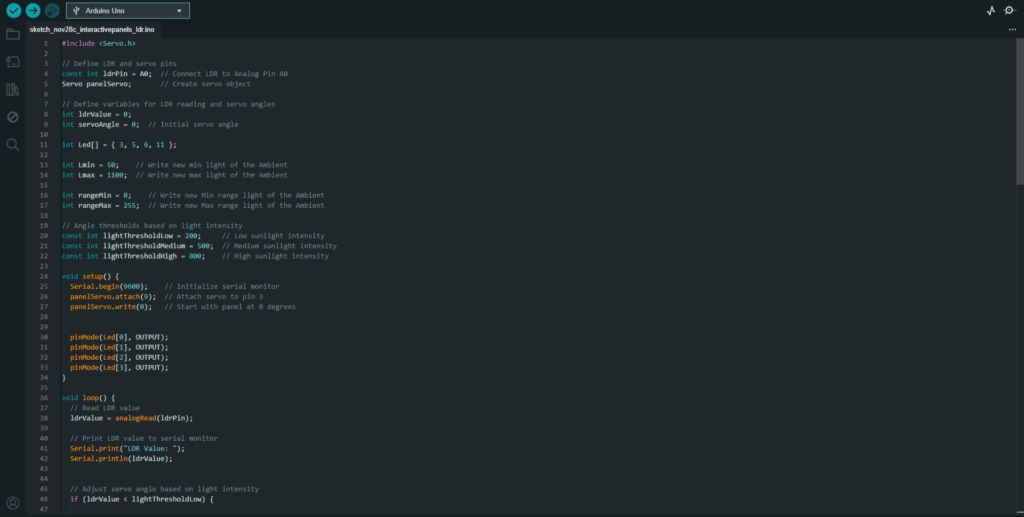
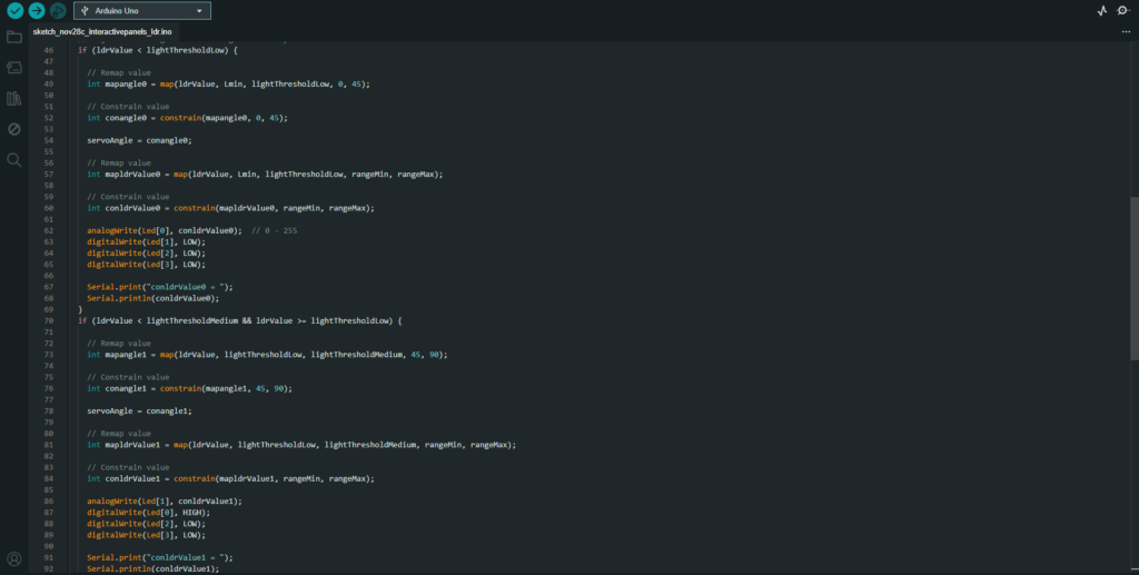
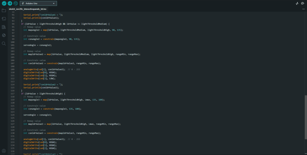
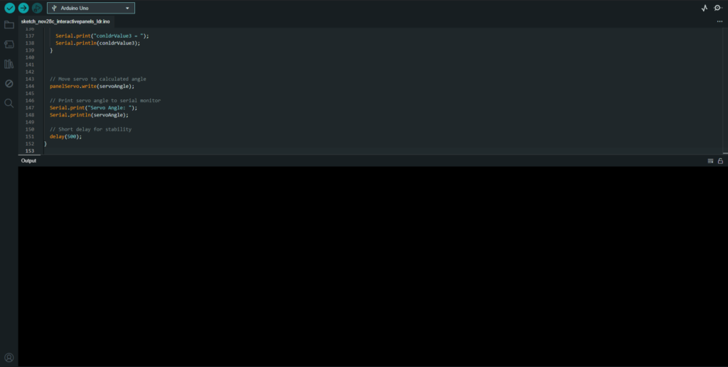
This project implements an Arduino-based sunlight-responsive system that dynamically adjusts a solar panel’s angle using an LDR sensor and a servo motor. The system detects sunlight intensity and positions the panel to maximize exposure, using predefined thresholds for low, medium, high, and very high light levels. LEDs serve as visual indicators of the detected light intensity, with brightness corresponding to sunlight strength. This project demonstrates efficient light tracking and energy optimization, ideal for small-scale solar tracking applications. The design utilizes components from the Arduino UNO R3 Starter Kit, ensuring accessibility and scalability.
Render
Functionality
Objective:
- Use an LDR (Light Dependent Resistor) to measure sunlight intensity.
- Adjust servo motor angles to reposition a solar panel based on light levels.
- Light up specific LEDs as visual indicators of the light intensity.
Required Components:
From the Arduino UNO R3 Starter Kit:
- Arduino UNO R3 (1 unit)
- Microcontroller to run the code and control components.
- Servo Motor (1 unit)
- To adjust the angle of the solar panel or any dynamic structure based on light intensity.
- LDR (Light Dependent Resistor) (1 unit)
- To measure sunlight intensity.
- 10kΩ Resistor (1 unit)
- For the LDR voltage divider circuit.
- LEDs (4 units)
- Visual indicators for light intensity levels.
- 330Ω Resistors (4 units)
- For limiting current to each LED.
- Jumper Wires
- For connections on the breadboard.
- Breadboard
- For assembling the circuit.
Demonstration of Final Prototype
Circuit Wiring:
- LDR Sensor:
- One terminal of the LDR connects to 5V.
- The other terminal connects to A0 and one leg of the 10kΩ resistor.
- The other leg of the resistor connects to GND.
- This forms a voltage divider, outputting a variable voltage to A0 based on light intensity.
- Servo Motor:
- Connect the servo motor’s signal wire to Pin 9.
- Connect the servo’s VCC to 5V and GND to GND.
- LEDs:
- Connect each LED’s anode (long leg) to pins 3, 5, 6, and 11 via 330Ω resistors.
- Connect each LED’s cathode (short leg) to GND.
Connections Diagram:
Here’s a text representation:
Component
LDR
Servo Motor
LED 0
LED 1
LED 2
LED 3
Arduino Pin
A0
Pin 9
Pin 3
Pin 5
Pin 6
Pin 11
Additional Notes
Use a 10kΩ resistor as a pull-down
Connect VCC to 5V and GND to GND
330Ω resistor in series
330Ω resistor in series
330Ω resistor in series
330Ω resistor in series
Code Breakdown:
- LDR Readings and Light Ranges:
- The LDR sensor reads ambient light intensity values (0–1023).
- These values are mapped into thresholds:
- 0-200: Low sunlight
- 200-500: Medium sunlight
- 500-800: High sunlight
- 800-1023: Very high sunlight
- Servo Movement:
- Servo angle is adjusted in steps:
- 0–45° for low light
- 45–90° for medium light
- 90–135° for high light
- 135–180° for very high light
- Servo angle is adjusted in steps:
- LED Indicators:
- LEDs light up based on the intensity:
- LED 0: Low light
- LED 1: Medium light
- LED 2: High light
- LED 3: Very high light
- LEDs light up based on the intensity:
- Value Mapping and Constraints:
- The map() function adjusts LDR values to servo angles and LED brightness levels.
- constrain() ensures mapped values stay within defined limits.


Functionality:
- Servo Panel Movement:
- As sunlight increases, the servo motor adjusts the panel’s angle to optimize exposure.
- Panel positions dynamically update according to the LDR readings.
- LED Indicators:
- LEDs provide a visual representation of light intensity:
- Low sunlight: Only LED 0 is ON.
- Medium sunlight: LED 1 is ON.
- High sunlight: LED 2 is ON.
- Very high sunlight: LED 3 is ON.
- Brightness of LEDs (via analogWrite) reflects the strength of sunlight within each range.
- LEDs provide a visual representation of light intensity:
Additional Improvements:
- Multiple Panels:
- Use multiple LDRs and servos for tracking sunlight in different directions.
- Real Solar Tracking:
- Implement dual-axis tracking by adding another servo for horizontal movement.
- Power Optimization:
- Use a dedicated power source for servos to prevent overloading the Arduino’s 5V regulator.

