Abstract:
In this class on Intelligent Prototyping within the MaAI program, we explored two distinct approaches to prototyping: 3D printing with robotic arms and real-time sensing with microcontrollers. Using parametric modeling tools, specifically Grasshopper, we designed and fabricated a series of 3D-printed clay pots. These included small, medium, and large-scale pots, with a focus on two standout designs: a medium-scale pot featuring a star-shaped profile that dynamically rotates along its height, and a large cylindrical pot showcasing a unique bump texture inspired by the IAAC logo for enhanced aesthetics and structural appeal.
On the microcontroller side, we developed a system using Arduino Uno paired with MPU6050 sensors—an accelerometer and gyroscope combination—to monitor and classify building sway caused by wind or seismic activity. This system provided real-time visual and auditory feedback to inform building occupants about potential safety concerns. Together, these projects highlight how robotics and microcontrollers can advance architectural design and safety in practical and innovative ways.
Robotic Fabrication
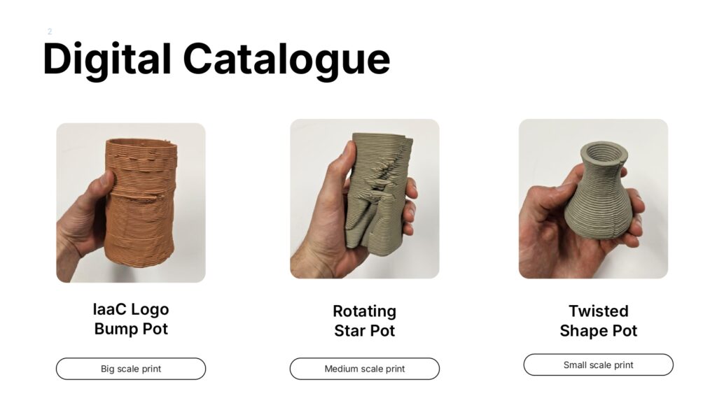
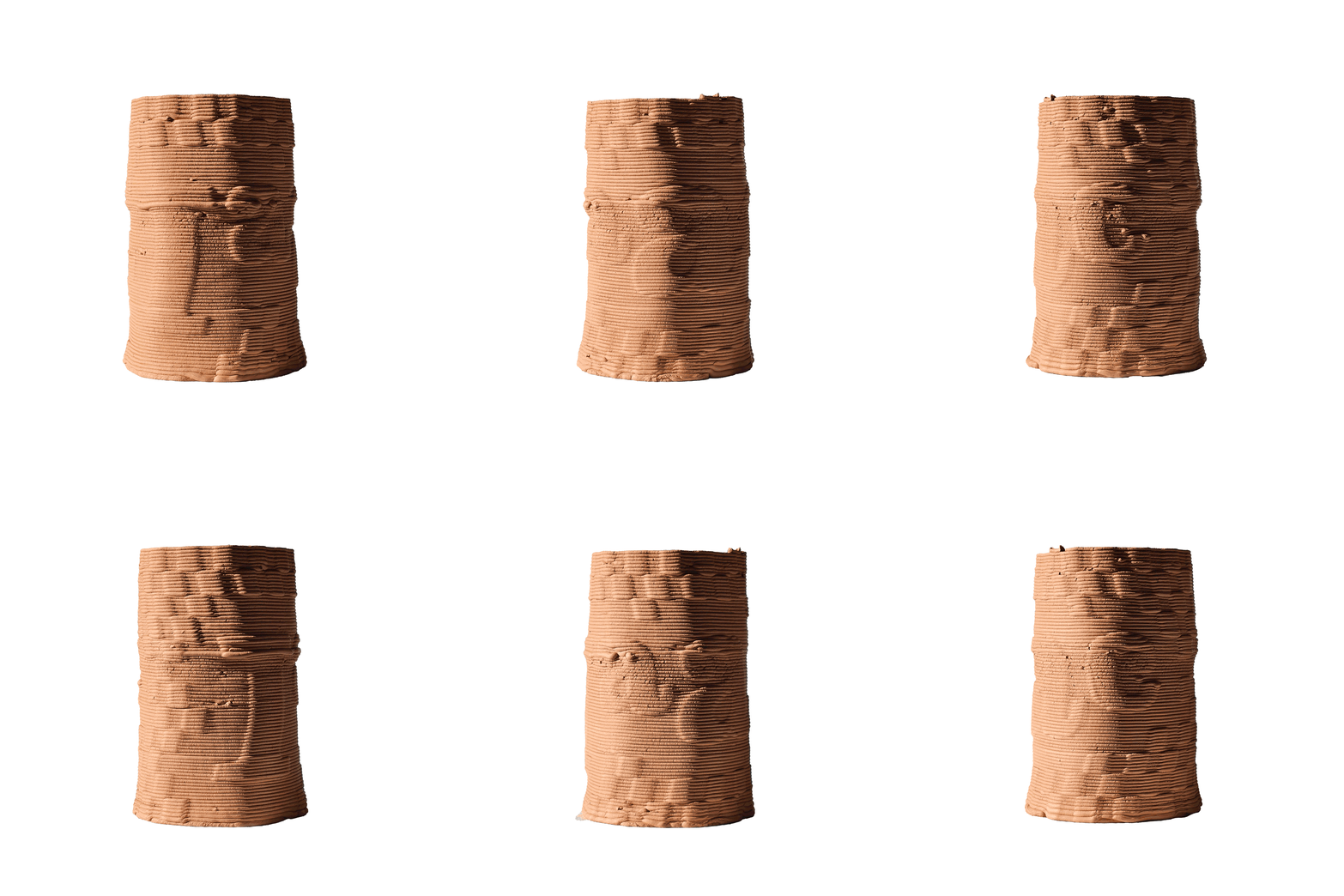
IAAC Logo Bump Pot
This 3D-printed pot, created using robotic manufacturing techniques, features a parametric design developed in Grasshopper, incorporating a distinctive bump texture to enhance its aesthetic and structural appeal.
- Designed using Grasshopper and Rhino
- Fabricated with robotic 3D printing technology in the the additive manufacturing process with clay.
- Features a unique “bump” texture, enhancing visual and tactile qualities.
Geometry construction:
- Base Shape: A cylindrical form was created in Grasshopper.
- Bump Map: The IaaC logo was applied as a bump map to add texture.
- Final Geometry: The textured shape was optimized for 3D printing with simplified lines.
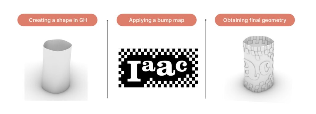
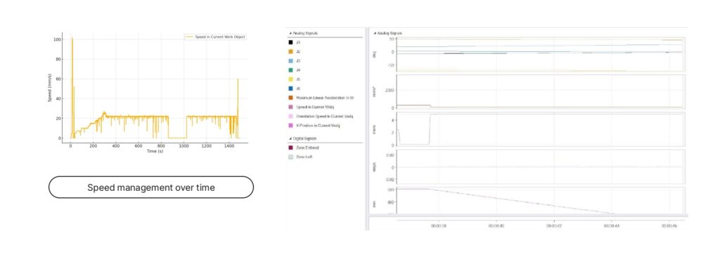
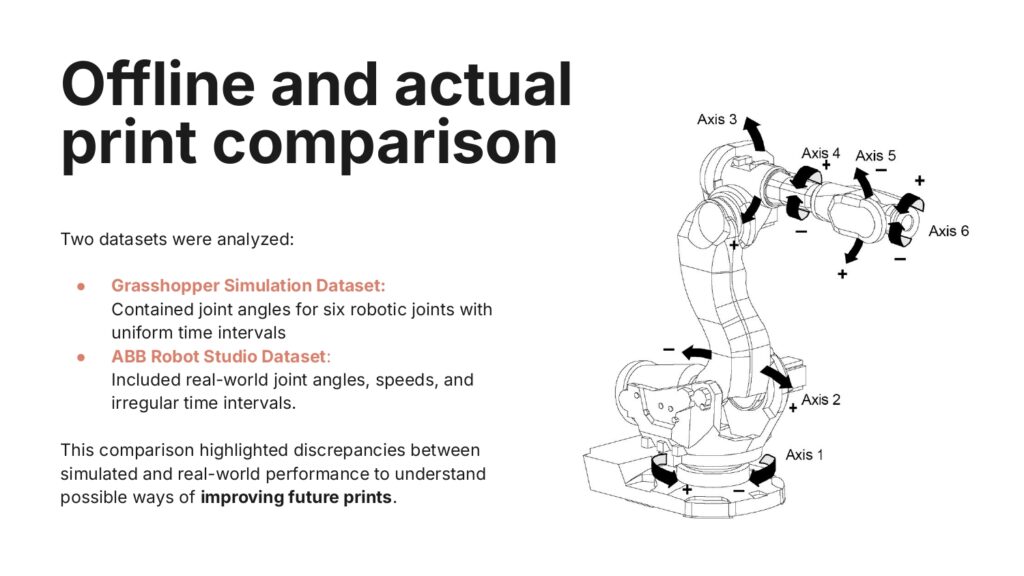
ABB Robot Studio data:
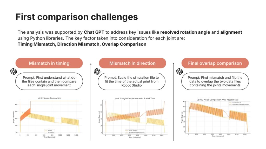
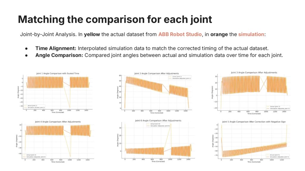
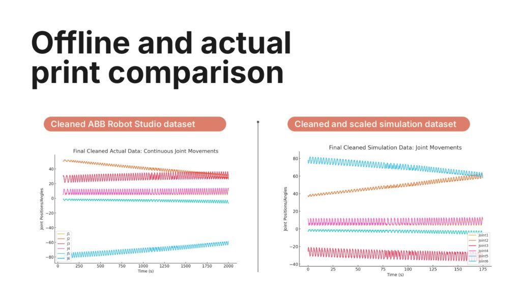
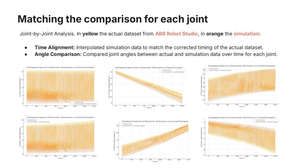
- Challenge: The dataset had inconsistent time intervals, requiring alignment with simulation data.
- Interruption: The print stopped at a specific point, necessitating data cleaning and adjustments.
- Speed Consideration: Speed variations were analyzed and factored into the process.
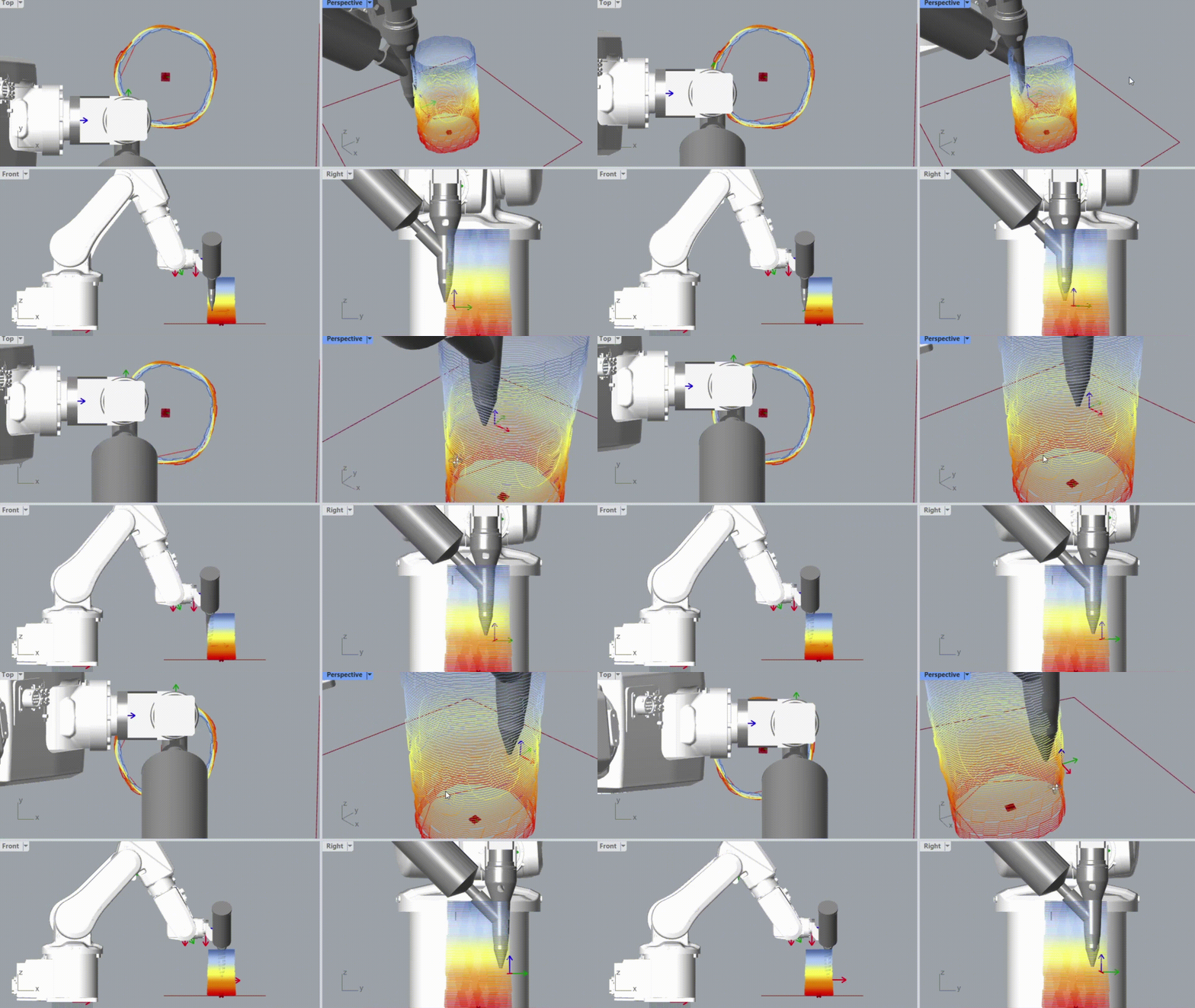
Offline Simulation:
- Bump Design: A mesh bump was created to balance the cantilevered structure and prevent clay collapse.
- Simplified Geometry: The mesh reconstruction ensured compatibility with simplified lines for printing.
- Layering Issue: Problems in the first layer were not initially considered, requiring adjustments for stability.
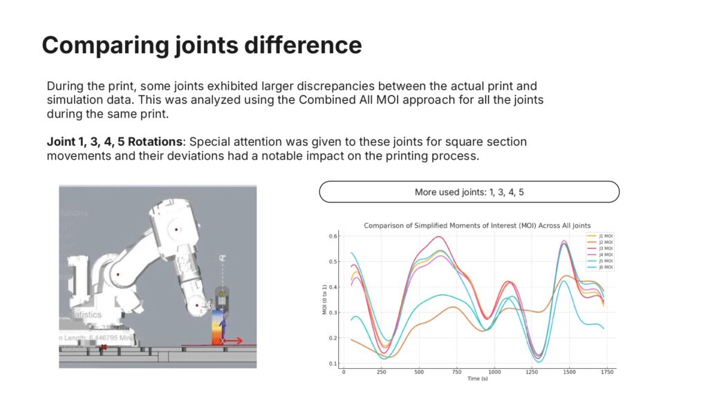
Rotating Star Pot
This 3D-printed pot, created using robotic manufacturing techniques, features a parametric design developed in Grasshopper, where a star-shaped profile rotates along the height, creating a dynamic and intricate form.
- Designed using Grasshopper
- Fabricated with robotic 3D printing technology in the additive manufacturing process with clay
- Challenging texture to define with the limitation of the additive manufacturing with clay and robots
Geometry construction and challenges:
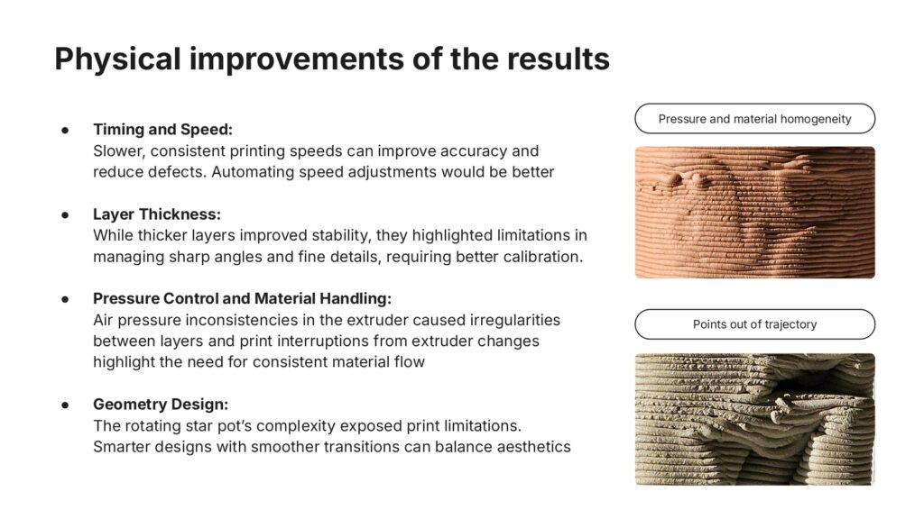
Challenges with Print Limitations: The detailed geometry pushed the boundaries of printing, with the sharp angles and fine details influenced by the layer thickness and material deposition constraints.
Unique Aesthetic and Structural Features: The unaltered geometry parameters produced a pot that demonstrates the raw potential and limitations of parametric design in additive manufacturing.
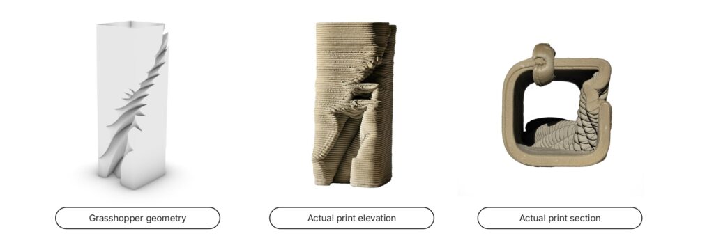
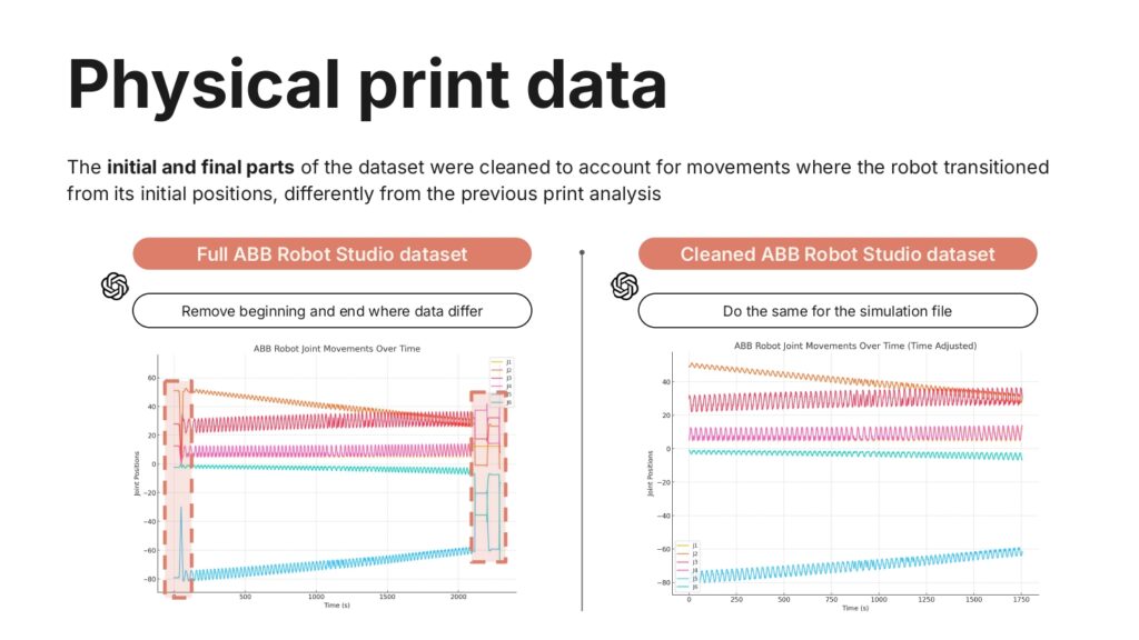
Offline Simulation:
- Complex Geometry: The design primarily involved a square shape with intricate internal details to create the rotating star effect.
- Trajectory Issues: Some points of the geometry extended beyond the printable area, forcing the robot to make non-printing movements to reach the next positions. These unnecessary transitions caused errors and deviations from the intended trajectory.
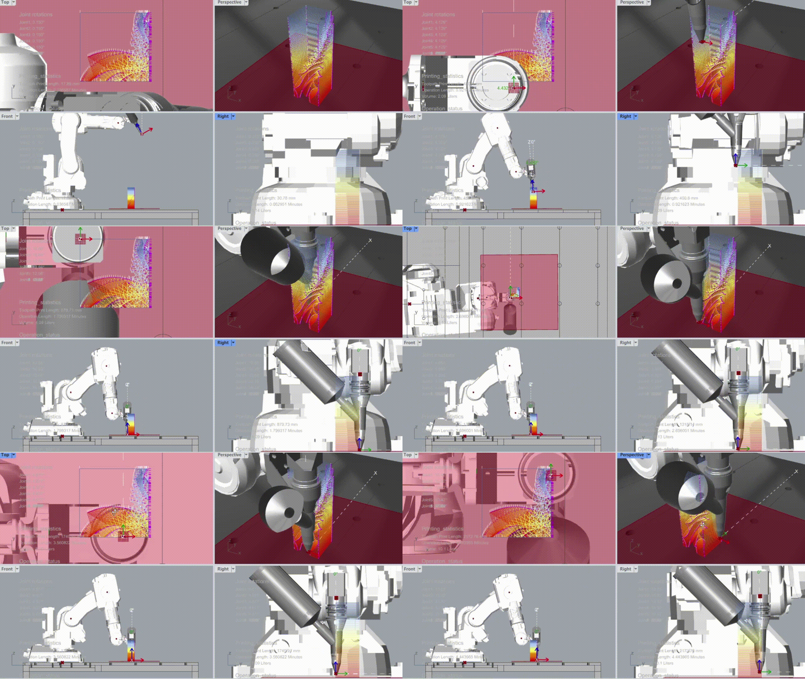


Key takeaways and improvements
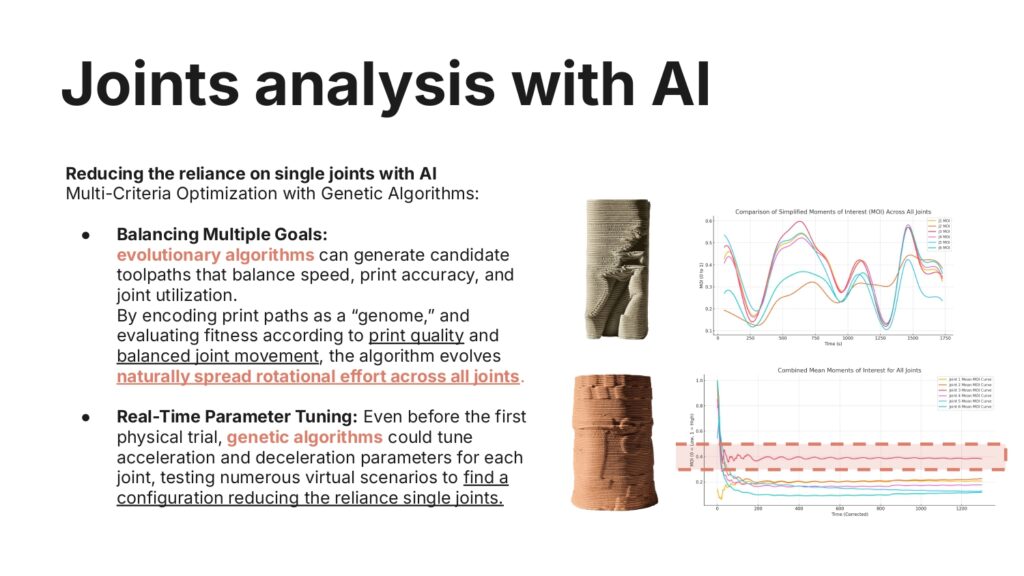
- Simulation Alignment: To achieve accurate comparisons, it is essential for the simulation to include the robot’s return to its initial and end positions. This ensures that all movement data is captured and comparable with the physical print.
- Consistent Data Points: The simulation and actual print must have a similar number of data points for each joint to allow for a fair and meaningful comparison. Misalignment in data density can result in inaccurate analysis.
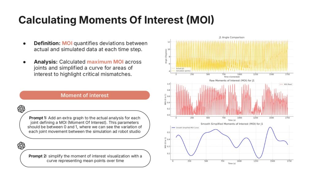
- Issues with Print Data: Both prints exhibited problems, particularly at the middle and end of the process. These issues created discrepancies when comparing data between the simulation and actual performance, emphasizing the need for robust data cleaning and error handling.
Microcontrollers
Concept:
Purpose:
- Monitor building sway in real-time to distinguish between wind-induced sway and seismic activity.
- Provide visual and auditory alerts for safety measures, such as evacuation.
Background:
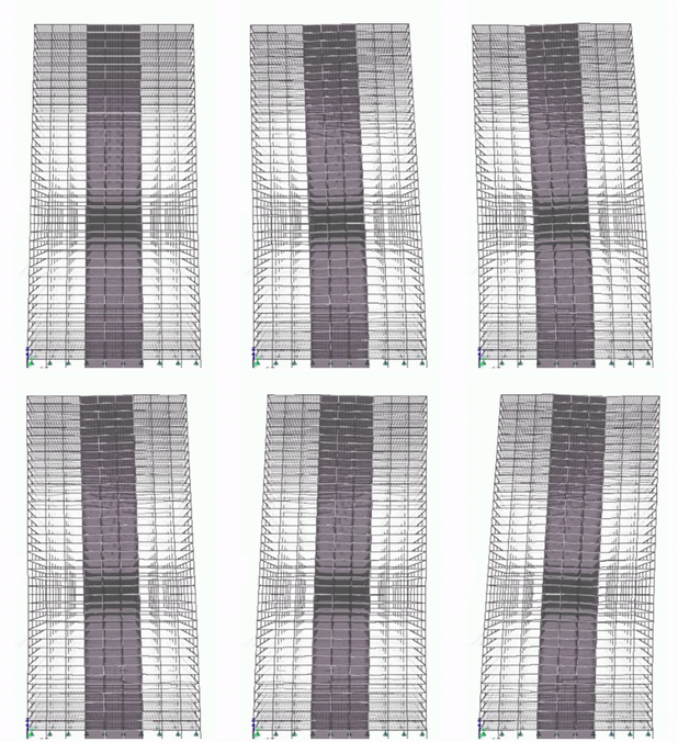
- Skyscrapers experience sway due to wind or earthquakes, and detecting dangerous motion is critical for safety.
- Inspired by modern structural health monitoring systems.
Objective:
- Detect and classify motion based on thresholds for acceleration and angular change.
- Trigger alarms for dangerous conditions.
Case Study:
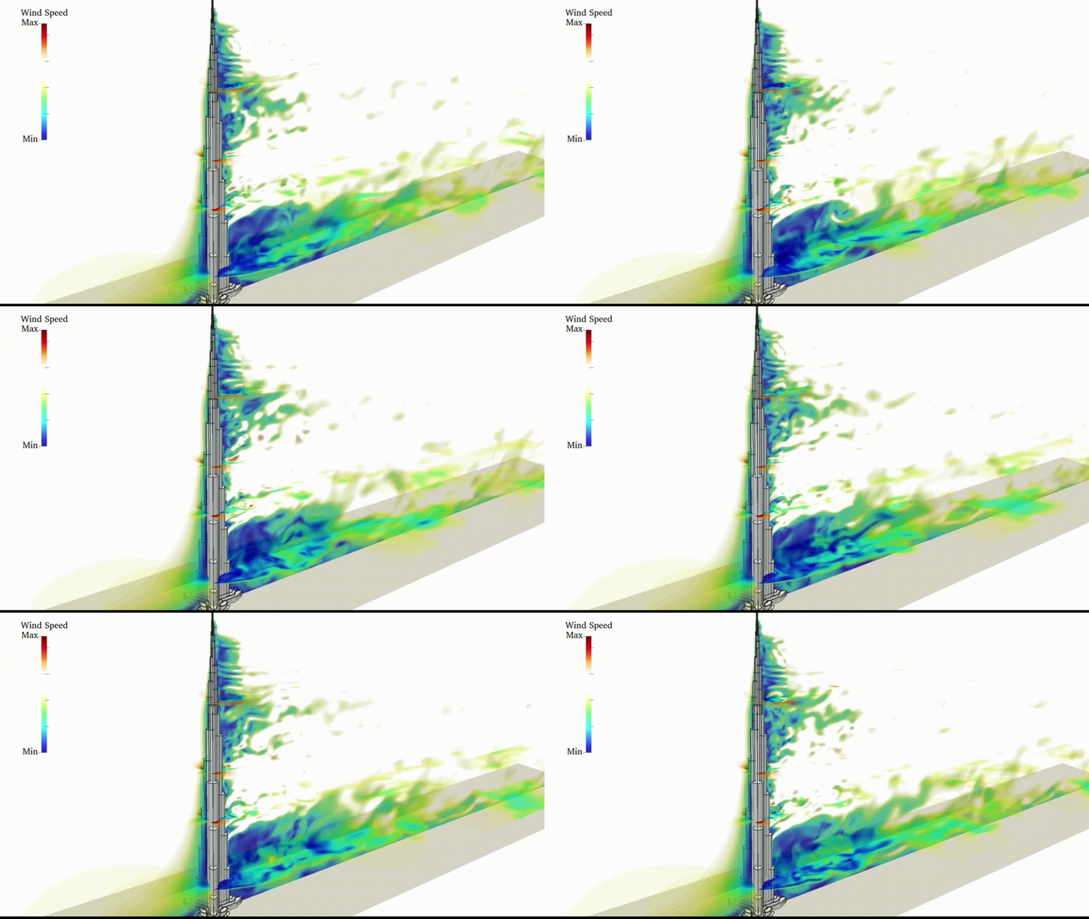
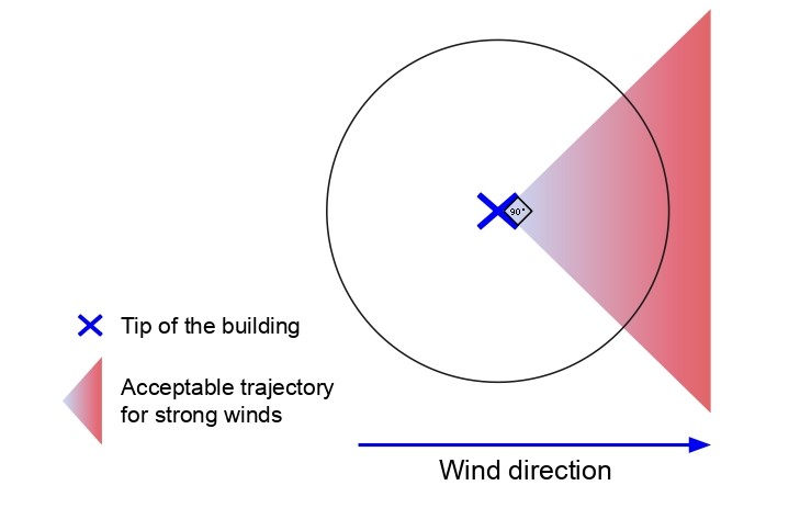
To better understand we took the example of the tallest building in the world, Burj Khalifa, that has an acceptable threshold of around 4m of swaying in strong wind conditions.
Our project is to get a device that can measure the swaying of the building on the top of it, and based on that gives directives to the building occupants.
Our objective is also to measure potential earthquakes. Where winds would sway the building in one direction, an earthquake would sway it in multiple directions, which is something that we can measure.

Bill of Materials (BOM)
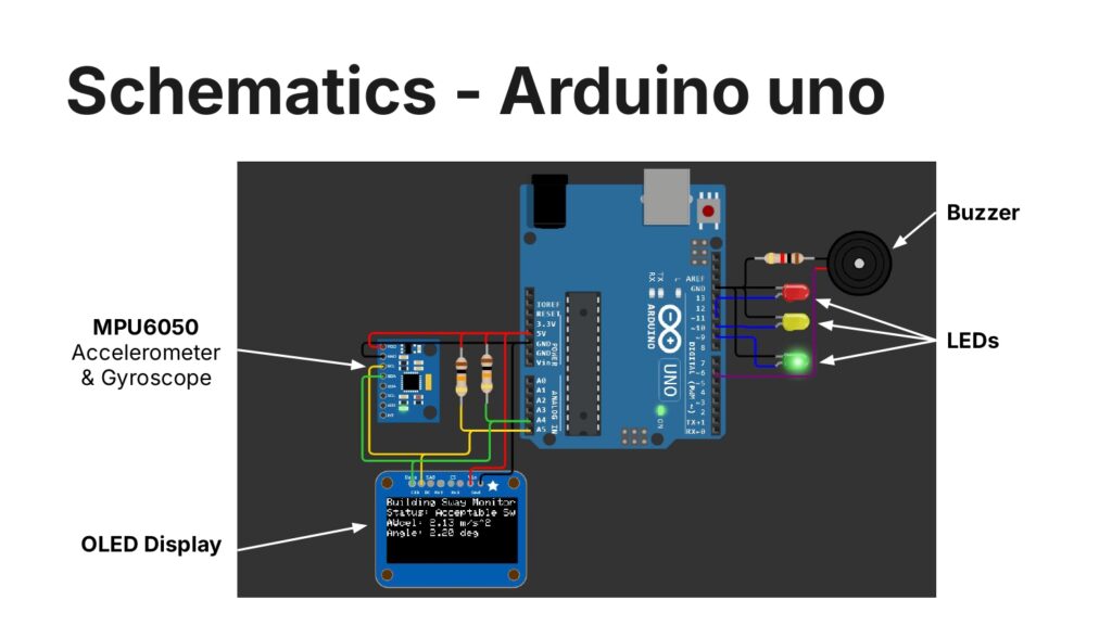
- Sensors:
- MPU6050 Accelerometer + Gyroscope.
- Microcontroller:
- Arduino Uno.
- Actuators:
- Green LED (1x).
- Yellow LED (1x).
- Red LED (1x).
- Active Buzzer (1x).
- Display:
- OLED Display (128×64).
- Power:
- 5V battery or USB power supply.
- Others:
- Resistors (220Ω, 1kΩ).
- Breadboard and jumper wires.
Software Overview
- Used libraries:
- Wire.h for I2C communication with MPU6050 and OLED.
- Adafruit_SSD1306 for OLED control.
- Key Features:
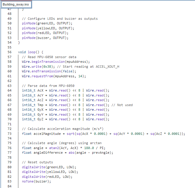
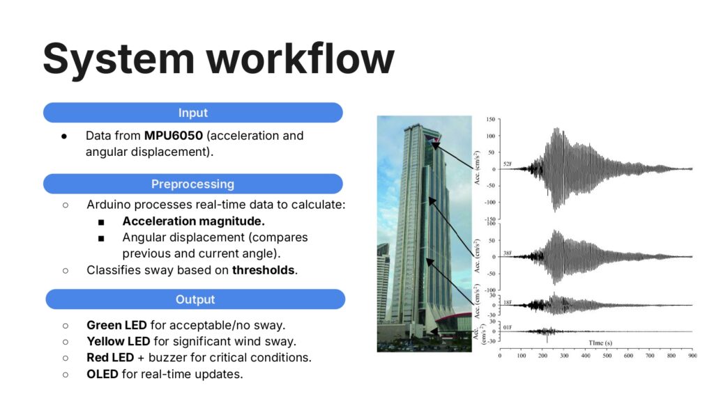
- Calculates acceleration magnitude and angle from MPU6050 data.
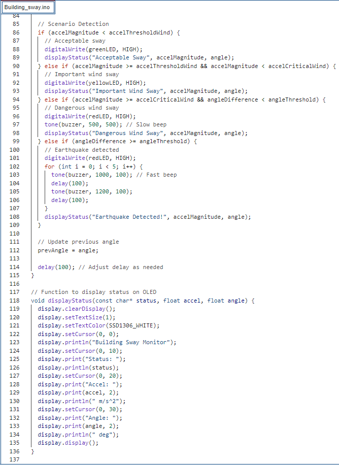
- Categorizes sway into 4 scenarios with visual (LEDs) and auditory (buzzer) alerts.
- Displays acceleration, angle, and status on OLED.
- Test scenarios:
- Wind Sway:
- Acceleration under 4 m/s².
- Angular displacement remains within 45°.
- Output: Green/Yellow LEDs based on thresholds.
- Earthquake Scenario:
- Rapid, large angular displacement (>90°).
- Output: Flashing Red LED and fast buzzer beeping.
- Wind Sway:
- Show data from Serial Monitor (acceleration and angles logged).
Arduino Code:

