CASE STUDY – GOOGLE HQ
Exploration from the Case Studies.`
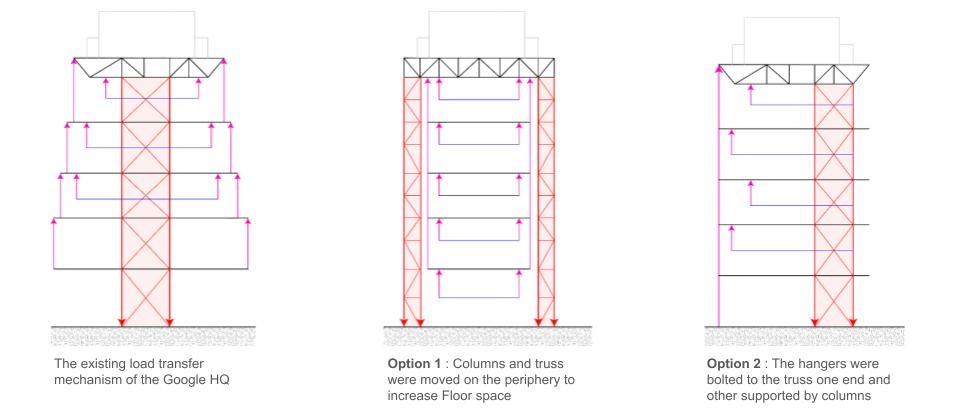
Diagram Analysis Set up – Load & Mass Distribution
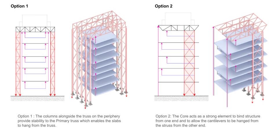
Beam Test Design Investigation
Truss with blocks (Vierendeel) using reclaimed hardwood exploring amount of overlap, number of blocks and impact of gaps between blocks.
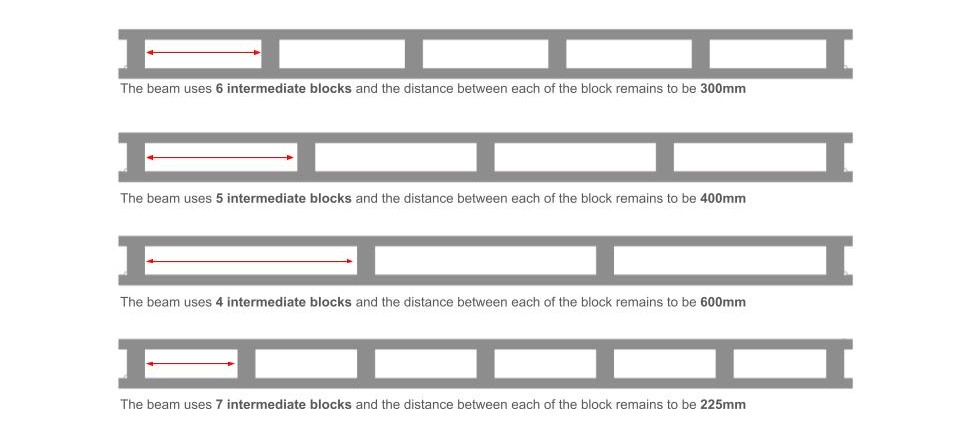
Beam Test Design Reclaimed Timber Block Truss

Beam Fabrication

Testing Videos
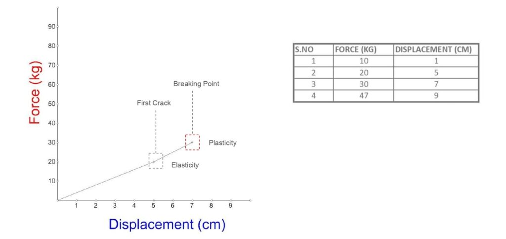
The beam exhibits elastic behavior until it reaches the point of plasticity. At this stage, when loads are released, the beam springs back to nearly its original position, but it doesn’t completely regain its initial shape. Understanding this transition helps in assessing the material’s performance and in designing more resilient structures.
Load Deflection Graph
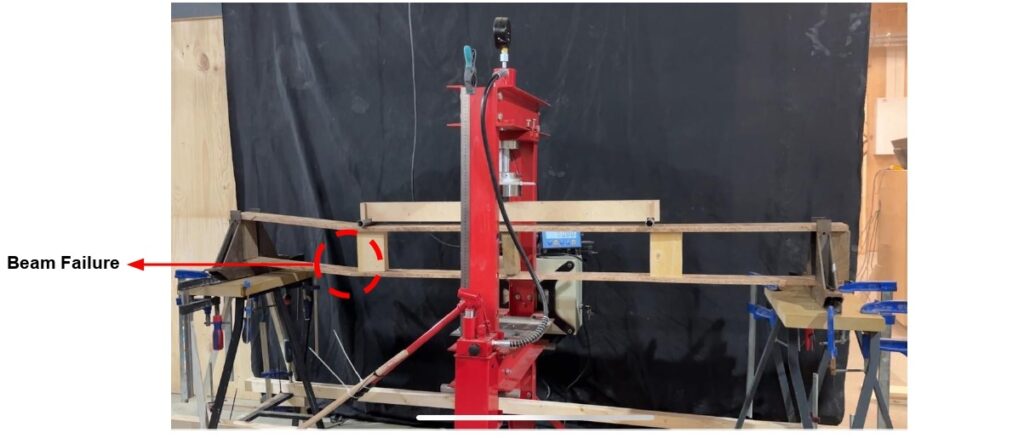
Beam Failure & Improvement
- Failure at the intermediate block was inevitable due to the excessive point load, which will cause displacement in the unbraced vertical element, as indicated by the Karamba analysis.
- Additional supports and bracing can enhance a structure’s load capacity, allowing for design flexibility to withstand higher loads or future expansions. Bracing provides diagonal reinforcement that resists shear forces, stabilizing the structure and improving rigidity.
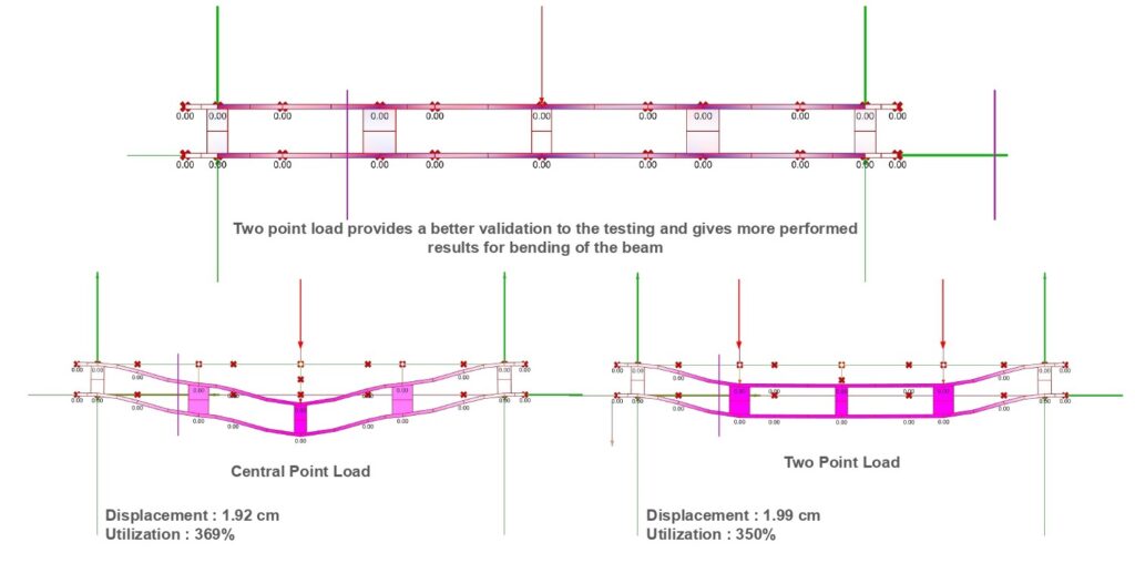
Beam tests Karamba3d Analysis with Point loads _ Sheer / Strength
Beam tests Karamba3d Analysis with Point loads _ Displacement of Intermediates
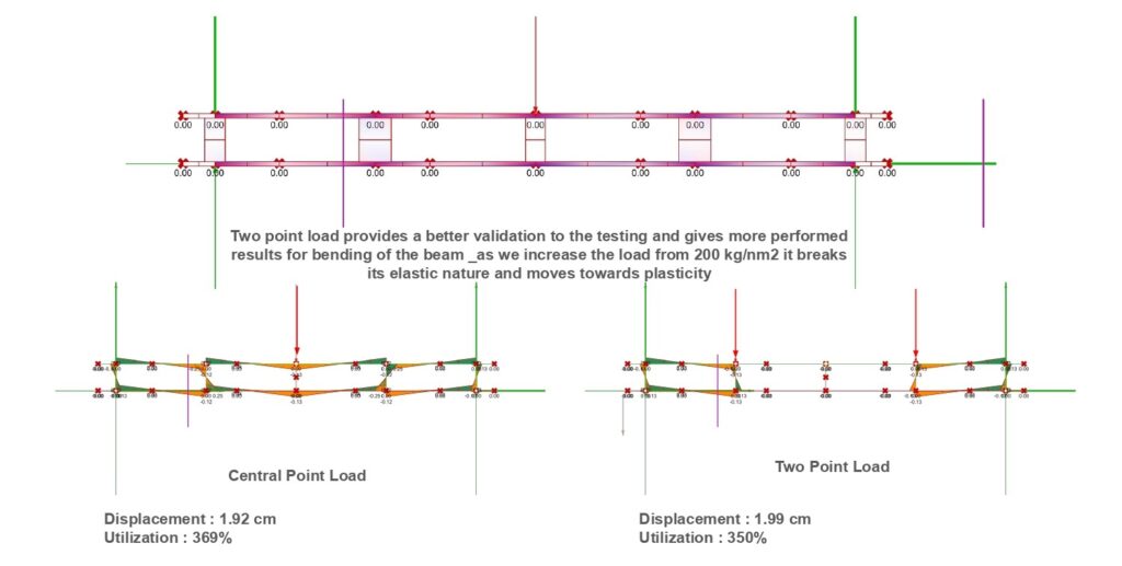
Analysis Comparison _ Implemented Beam test to Design
- We anticipated the beam to withstand a displacement and break under a 60 kg force, but in practice, it failed at just 40 kg.
- we expect the beam to have a displacement of “1.90 meters” at both the ‘beginning and the end’ of the beam (denoted by 2.2 and Length). However, in real-world testing, we observed that the beam broke and exhibited “asymmetrical displacement” (i.e., displacement occurred predominantly on one side). This discrepancy indicates the beam exceeded its material limits under applied loads, leading to structural failure

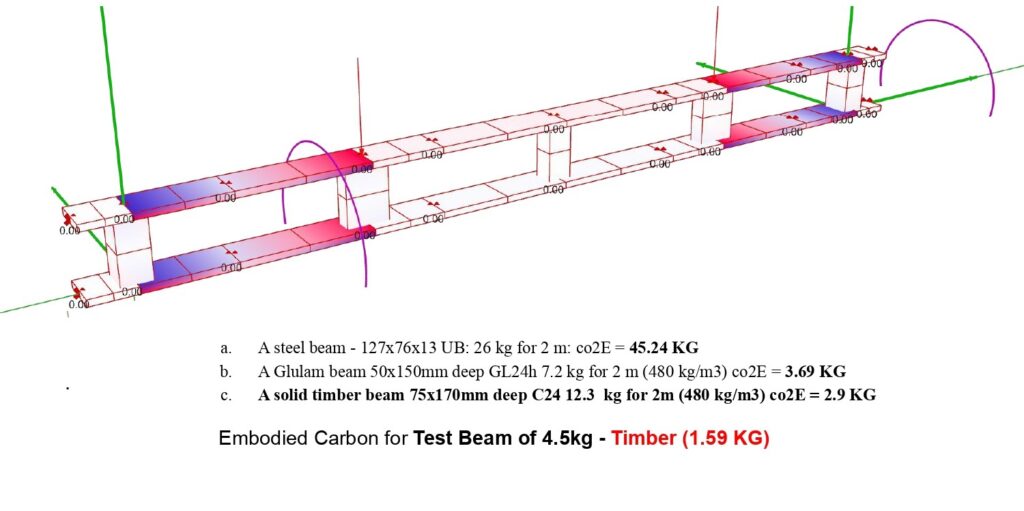
Embodied Carbon
