Introduction to Digital Fabrication Seminar
Faculty: Ricardo Mayor, Hamid Peiro, Shyam Francesco Zonca
Faculty Assistant: Sheikh Rizvi Riaz, Federico Caldi, Vivek Venkateshappa
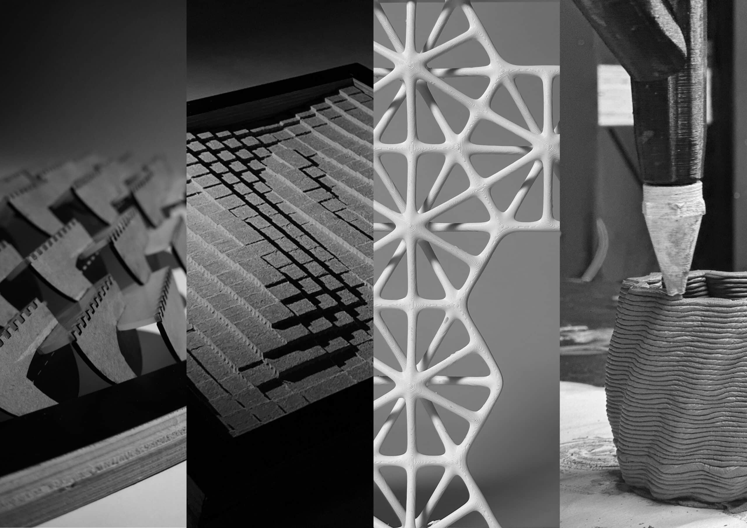
In our Introduction to Digital Fabrication course we developed a small ecosystem of “bio” prototypes that test how code, machines and matter can co-evolve. Across four exercises we treated each fabrication tool as a way to grow architecture rather than just draw it. BioJoint uses the laser cutter to turn flat sheets into an interlocking, organism-like structure that plays with light and shadow. BioPixel translates a digital height map into a CNC-milled relief, where each wooden “pixel” can host micro-greens and micro-shadows. With BioMesh, 3D printing becomes a way to weave porous, load-bearing skins in which structure and opening are one continuous geometry. Finally, BioCup brings in robotic clay printing, using an ABB arm to coil a simple vessel from wet earth, layer by layer. Together, these four pieces trace a trajectory from 2D to 3D, from grid to mesh, from inert material to potentially living surface, an early catalogue of how digital fabrication can prototype future bio-informed architectures.
BioJoint – Laser Cutting
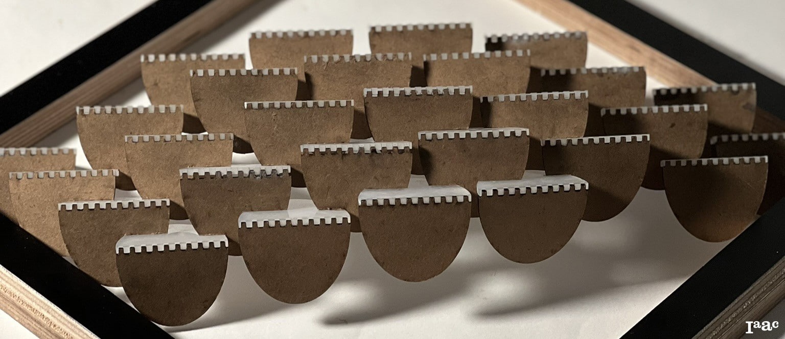
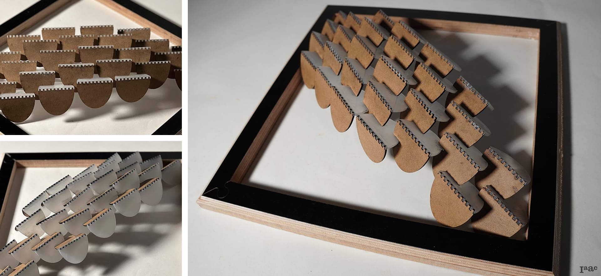
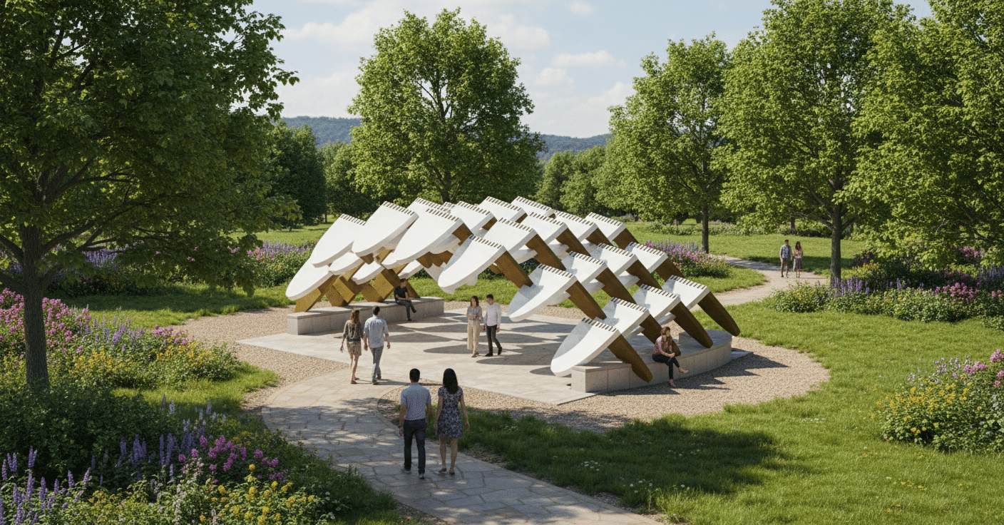
BioJoint is an experimental interlocking system that utilizes two laser-cut materials to create a sculptural 3D volume from flat 2D components.
The design, which resembles natural organisms and combines acrylic with MDF wood, promotes a dynamic interplay of transparency, light, and shadow. Its structural porosity and organic geometry make it suitable for diverse uses, such as partitions, pavilions, or shading devices, showcasing the potential of digital fabrication in nature-inspired architecture.
Process and Design
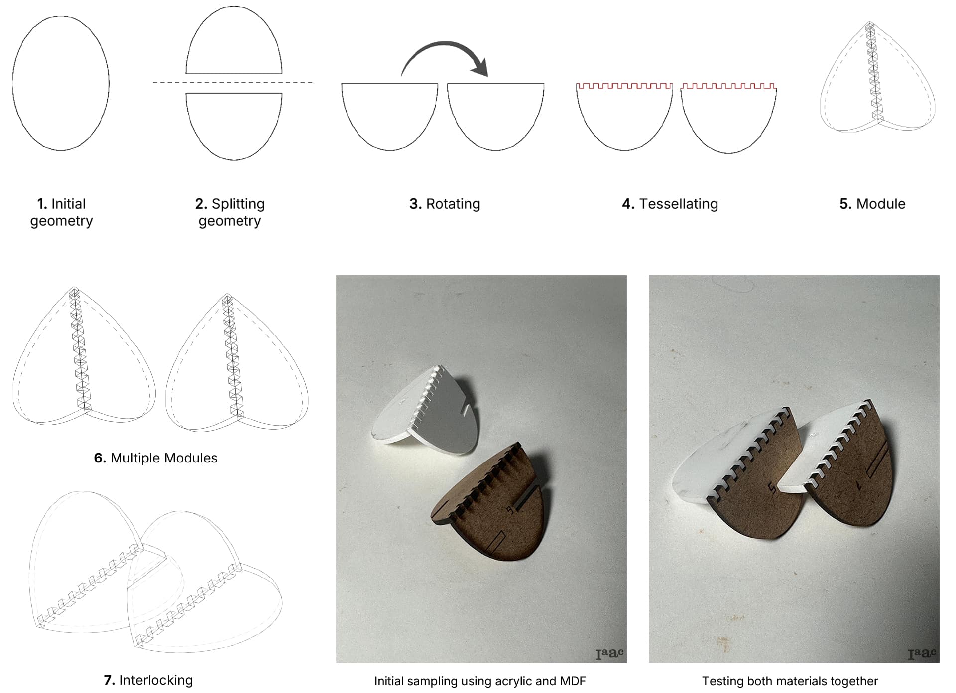
Project Diagrams and Final Design
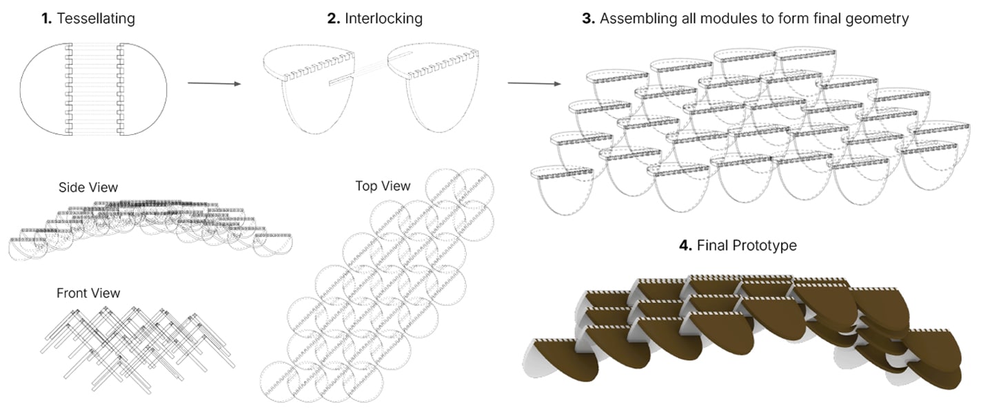
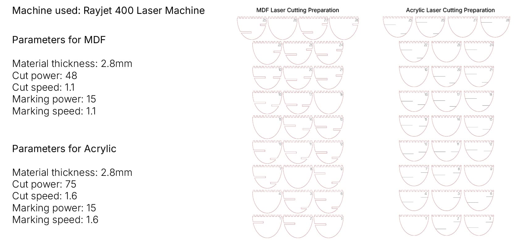
Fabrication Strategy

Prototype Pictures
BioPixel – CNC Milling
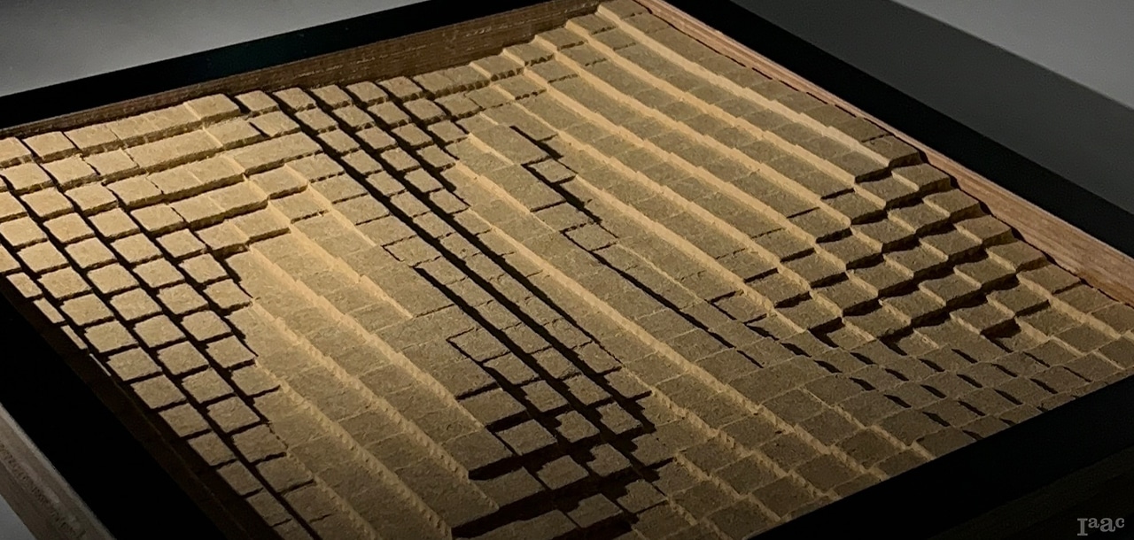
BioPixel explores the intersection between digital fabrication and ecological design.
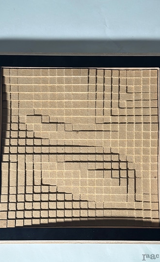
The panel translates a pixelated digital pattern into a physical, three-dimensional surface that can host micro green pockets and dynamic light effects. Each pixel’s depth variation generates texture, shadow, and potential for natural growth, transforming a rigid digital grid into a living architectural skin. Chosen as our CNC project, BioPixel demonstrates how computation and material fabrication can merge to create adaptive, responsive facade systems.
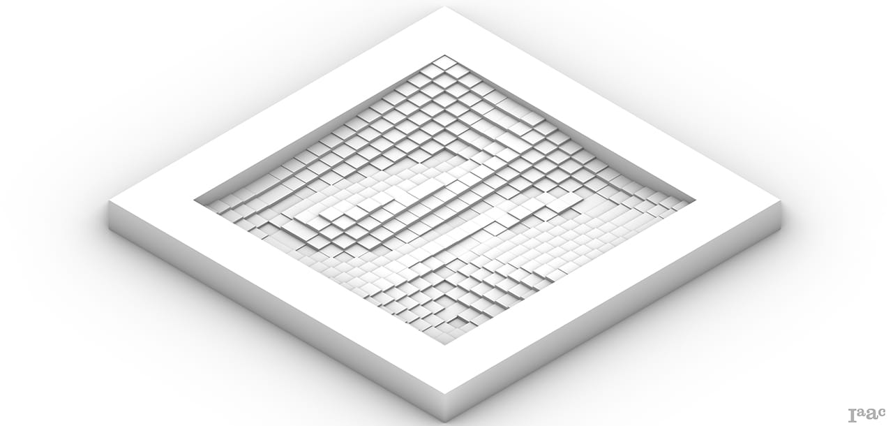
Our project is an inspiration from the “Pixel Facade” system. This system is an adaptive scalable and repeatable building system that can be applied to various building typologies.
Project Diagram- Technical Drawing
We generated a grid of points, used curve attraction to define height variation, and extruded each pixel based on proximity values. The resulting surface translates digital data into a dynamic facade pattern.
Fabrication Strategy
Biopixel was created using a 30 mm MDF panel as the primary material. The machining was carried out on a CNC ShopBot, using the ShopBot_MTC post processor to ensure accurate toolpath execution. The workpiece measured 400 × 400 × 30 mm, providing a compact yet solid volume suitable for detailed CNC operations. Since the project has already been completed, this information serves as a technical summary for documentation and blogging purposes.
01 – Engraving
Flat Mill
Flute: 2
Diameter: 6
Spindle Speed: 12000
Cut Direction: Natural
Total Cut Depth: 3mm
Total mill time: 0.3 min.
02 – Horizontal Roughing
Flat Mill
Flute: 1
Diameter: 8
Spindle Speed: 12000
Cut Direction: Downcut
Stepdown Control (dZ): 50%
Stepover Distance: 60%
Total mill time: 35 min.
03 – Parallel Finishing (1)
Flat Mill
Flute: 2
Diameter: 6
Spindle Speed: 12000
Cut Direction: Mixed
Stepover Distance: 3.175 (60%)
Angle of Cuts: 0
Total mill time: 15 min.
04 – Parallel Finishing (2)
Flat Mill
Flute: 2
Diameter: 6
Spindle Speed: 12000
Cut Direction: Mixed
Stepover Distance: 3.175 (60%)
Angle of Cuts: 90
Total mill time: 15 min.
05 – Profiling
Flat Mill
Flute: 2
Diameter: 6
Spindle Speed: 12000
Cut Direction: Upcut
Number of Bridges: 5
Total mill time: 6 min.
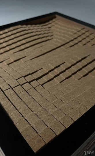
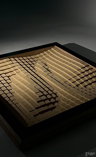
Prototype Pictures
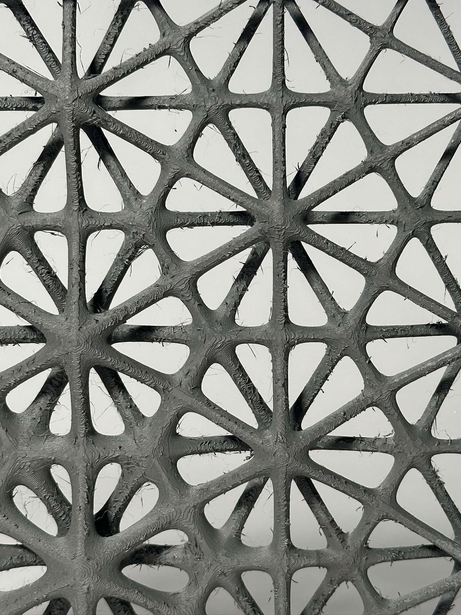
BioMesh – 3D Printing
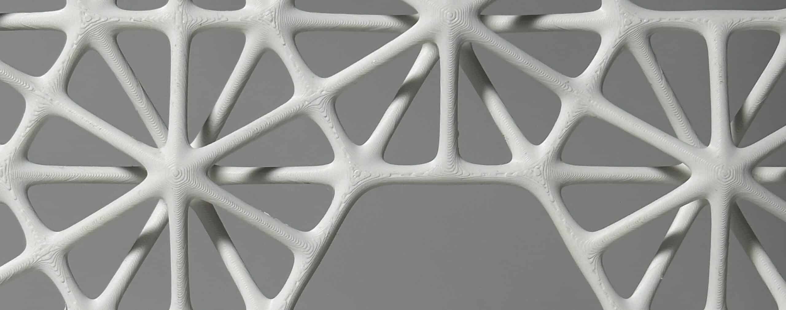
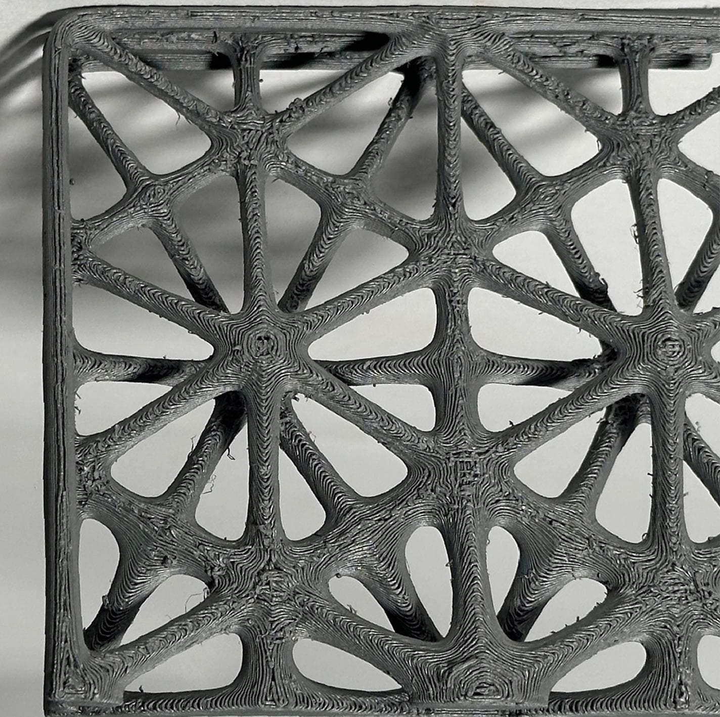
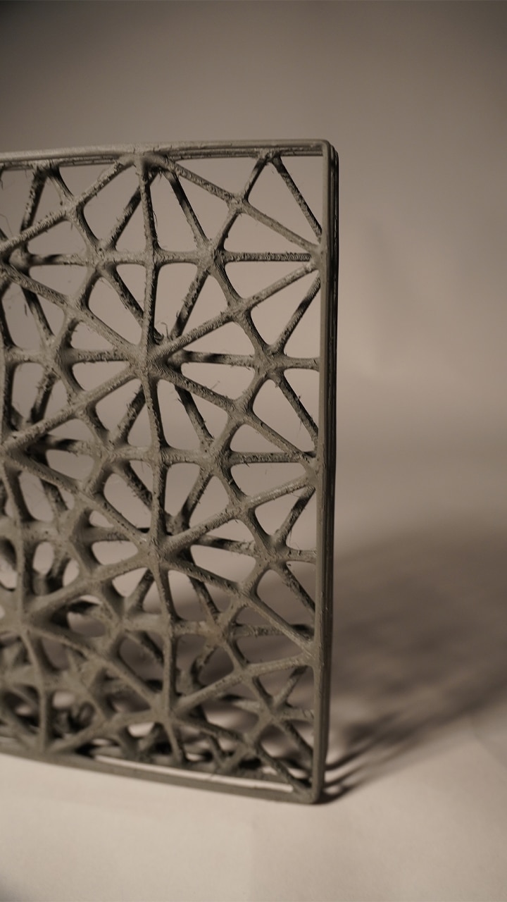
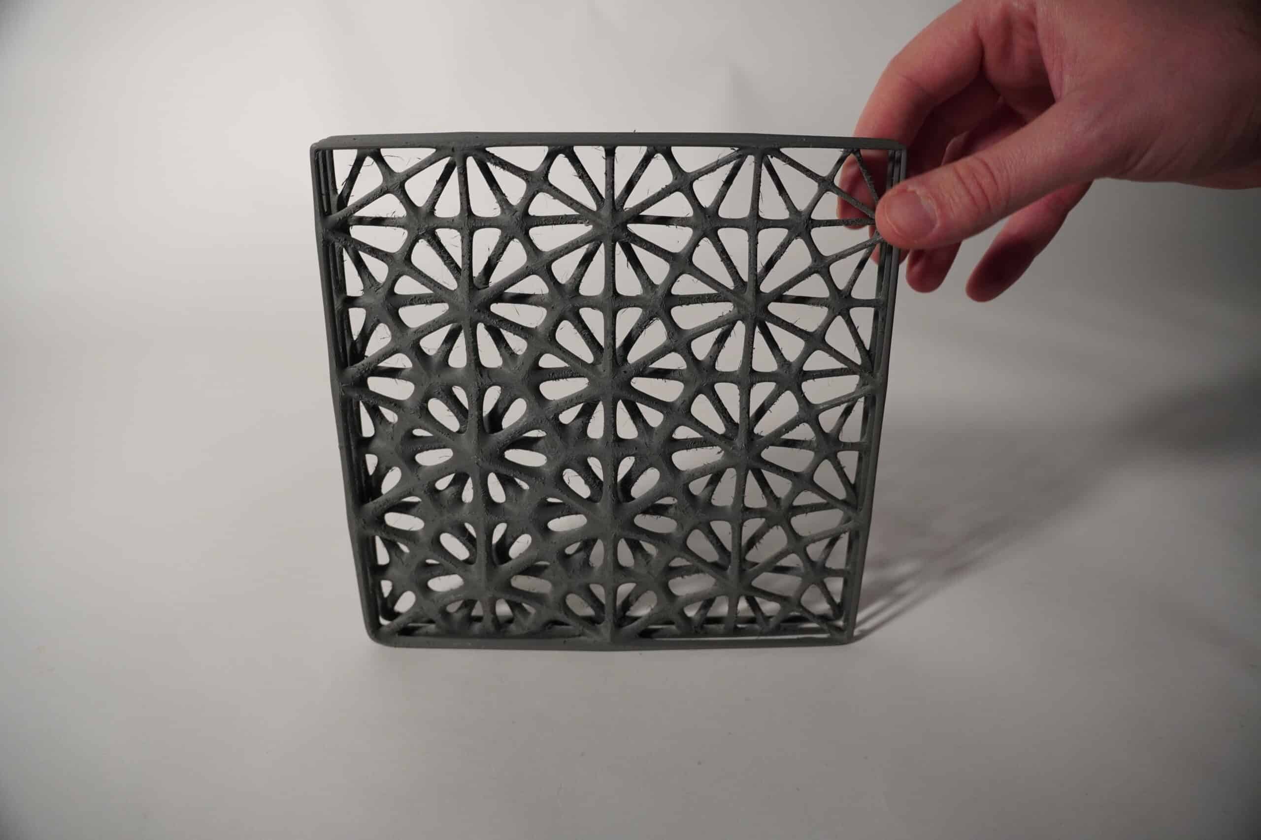
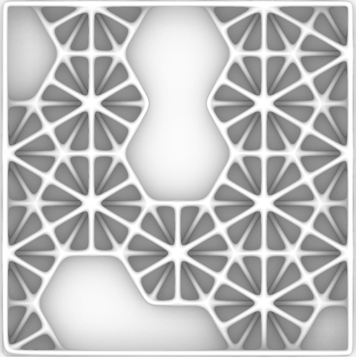
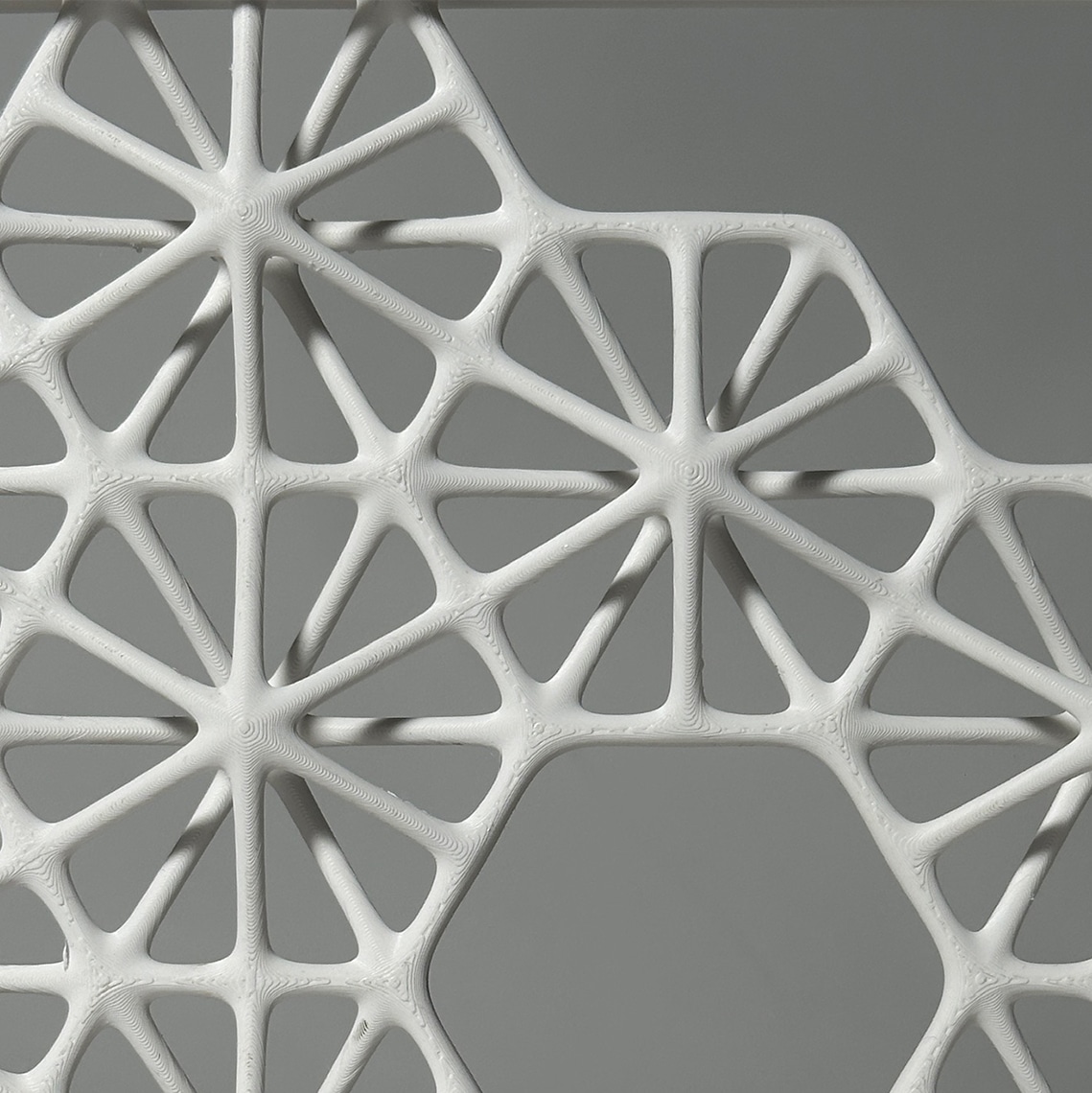
BioMesh is a modular pattern where structure and opening are the same thing. A network of ribs forms graded holes that steer light, air and views while carrying load. One unit reads as a frame; many units join into screens, façades or light cores. The geometry can thicken into columns or flatten into panels, scaling from furniture to building skin. It is a simple kit for breathable, lightweight architecture.
Process and Design
We divided our model into four sections and printed the section with the thinnest lines as a sample before beginning to print our final model.
Prepare Time: 6m 14s
Model printing time: 2h 35m
Total time: 2h 41m
First Design
Material: PLA
Machine: Bambu Lab A1
Workpiece volume: 200mmx200mx30mm
Total Filament: 146.11 g
Model Filament: 65.90 g
Support Time: 8h53m
Top Z Distance: 0.23
Model Printing Time: 17h50m
Total Time: 21h39m
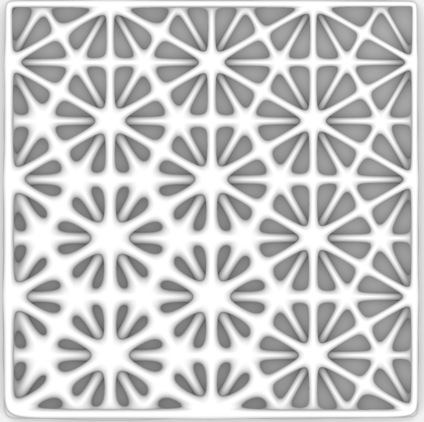
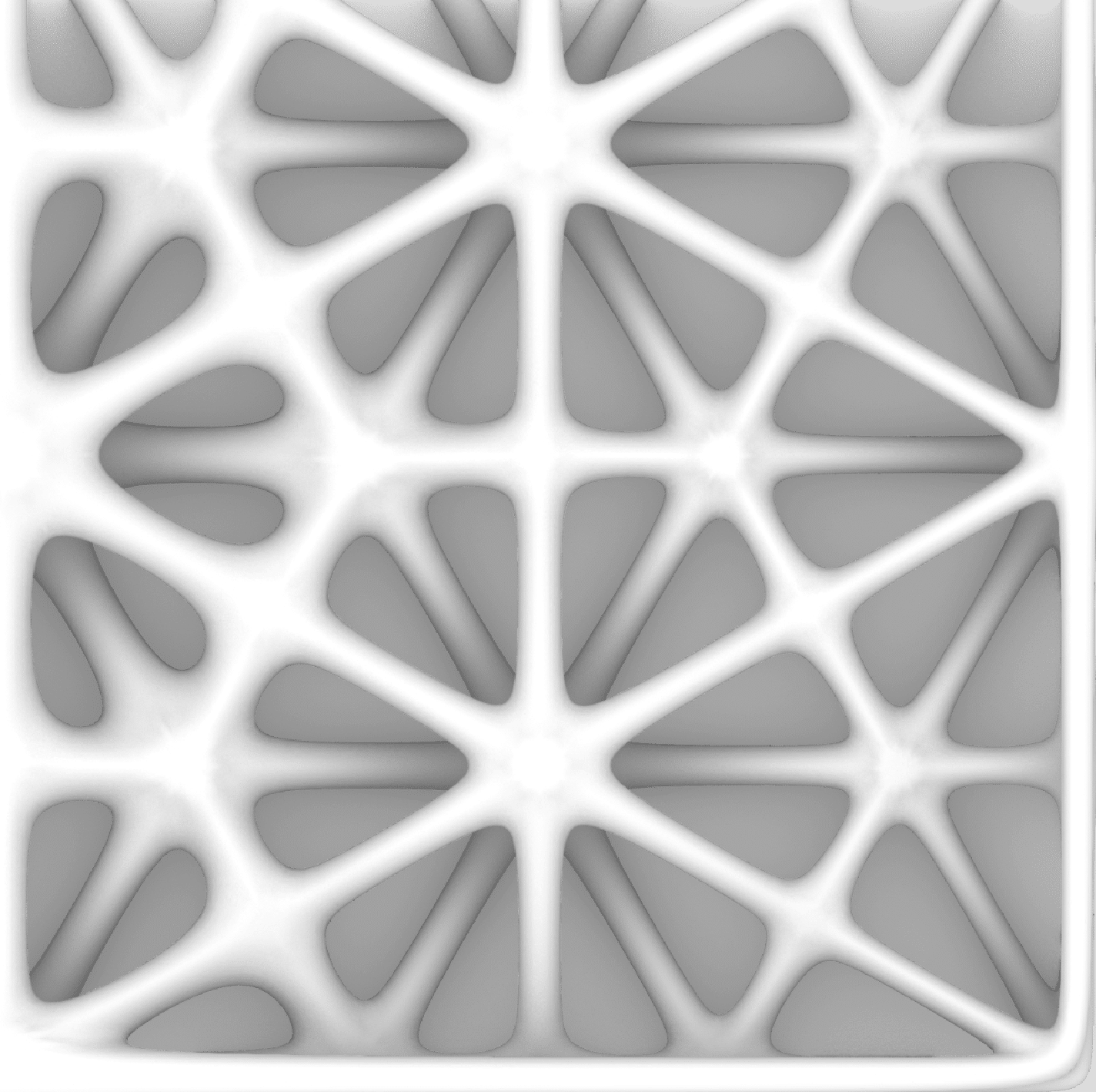
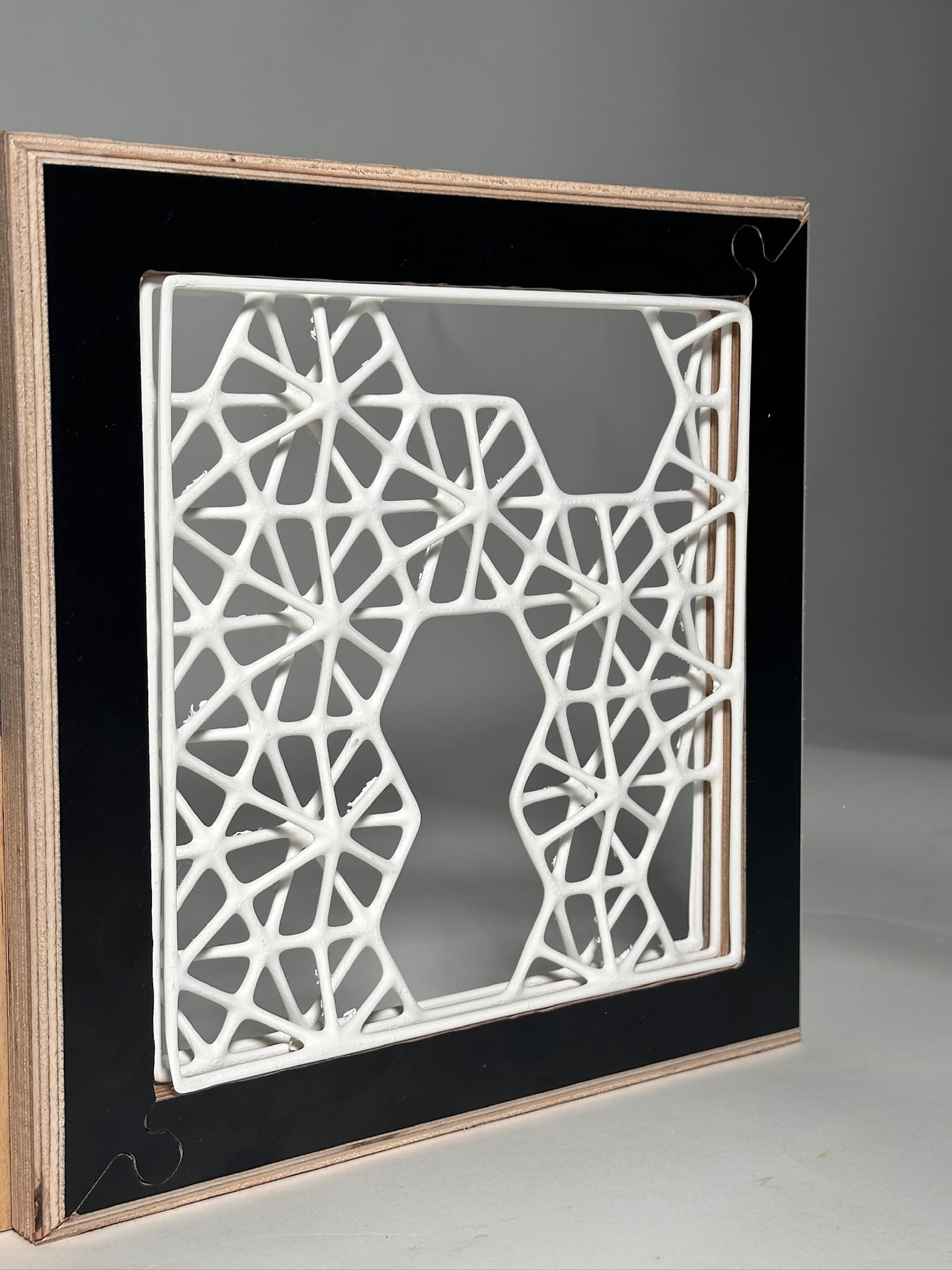
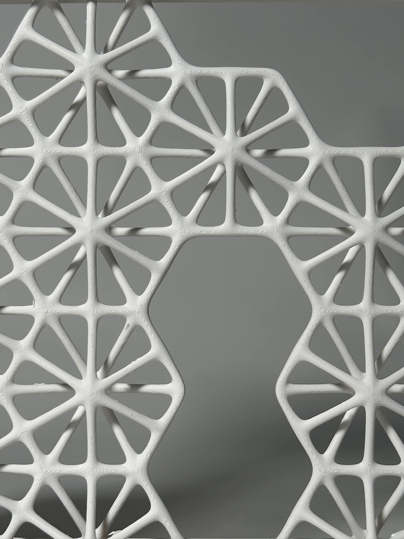
Final Design
In order to create a more parametric and potentially flexible design, we are recreating the current digital model in Grasshopper with additional forms, gaps, and shadows.

Prepare Time: 6m 30s
Timelapse Time: 4m 32s
Model printing time: 17h 50m
Total time: 18h 1m
Project Diagrams- Technical Drawing
Fabrication Strategy
Prototype pictures
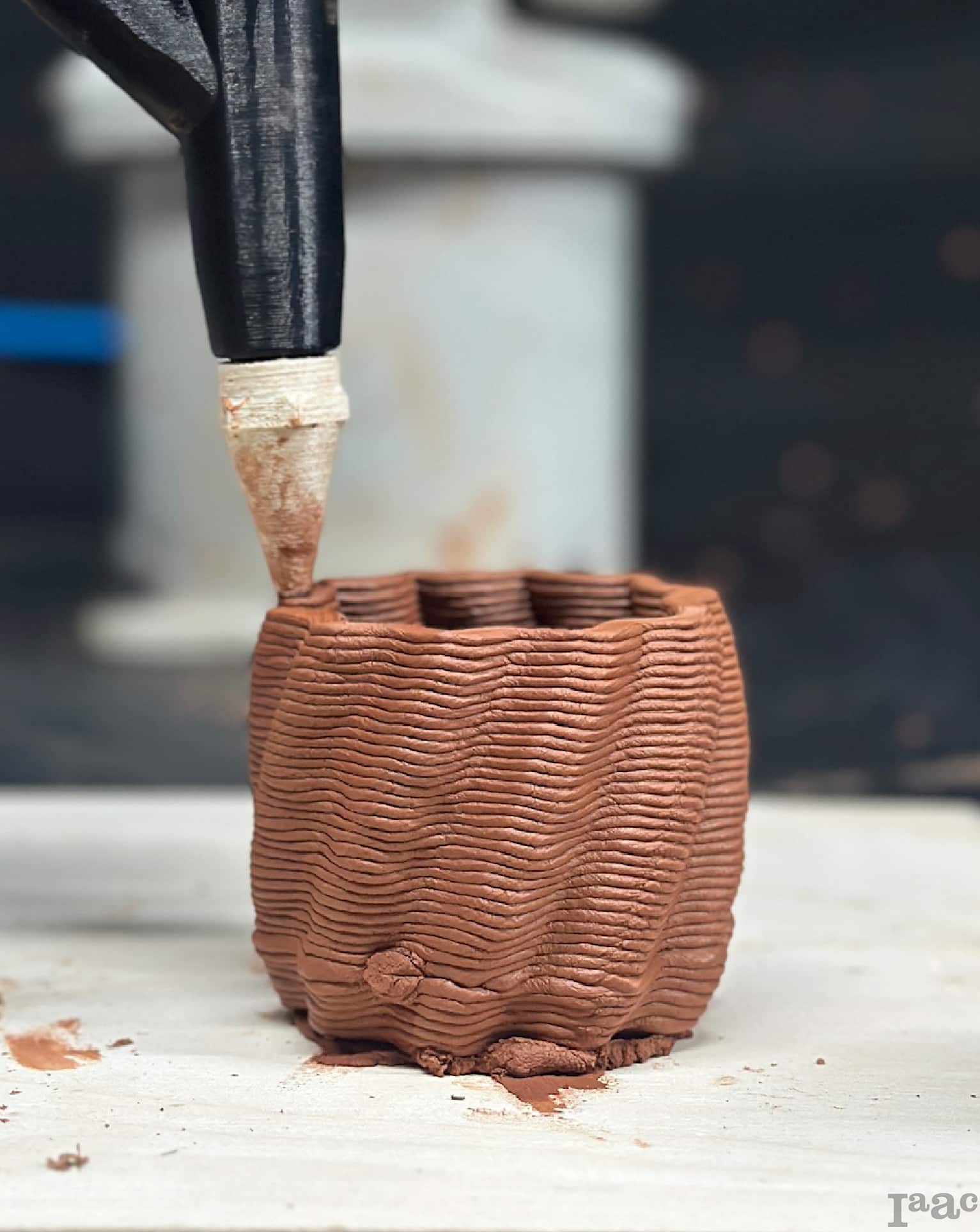
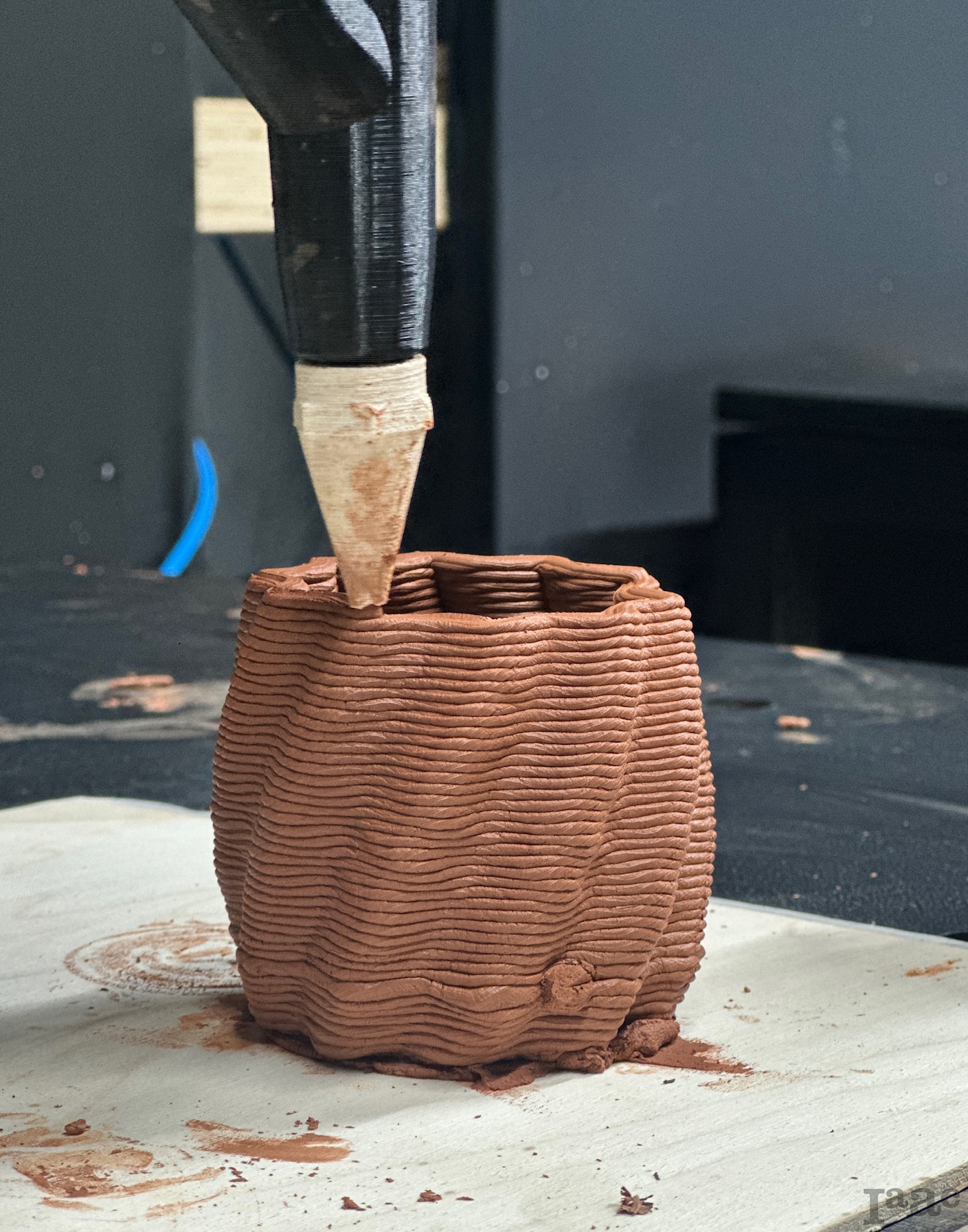
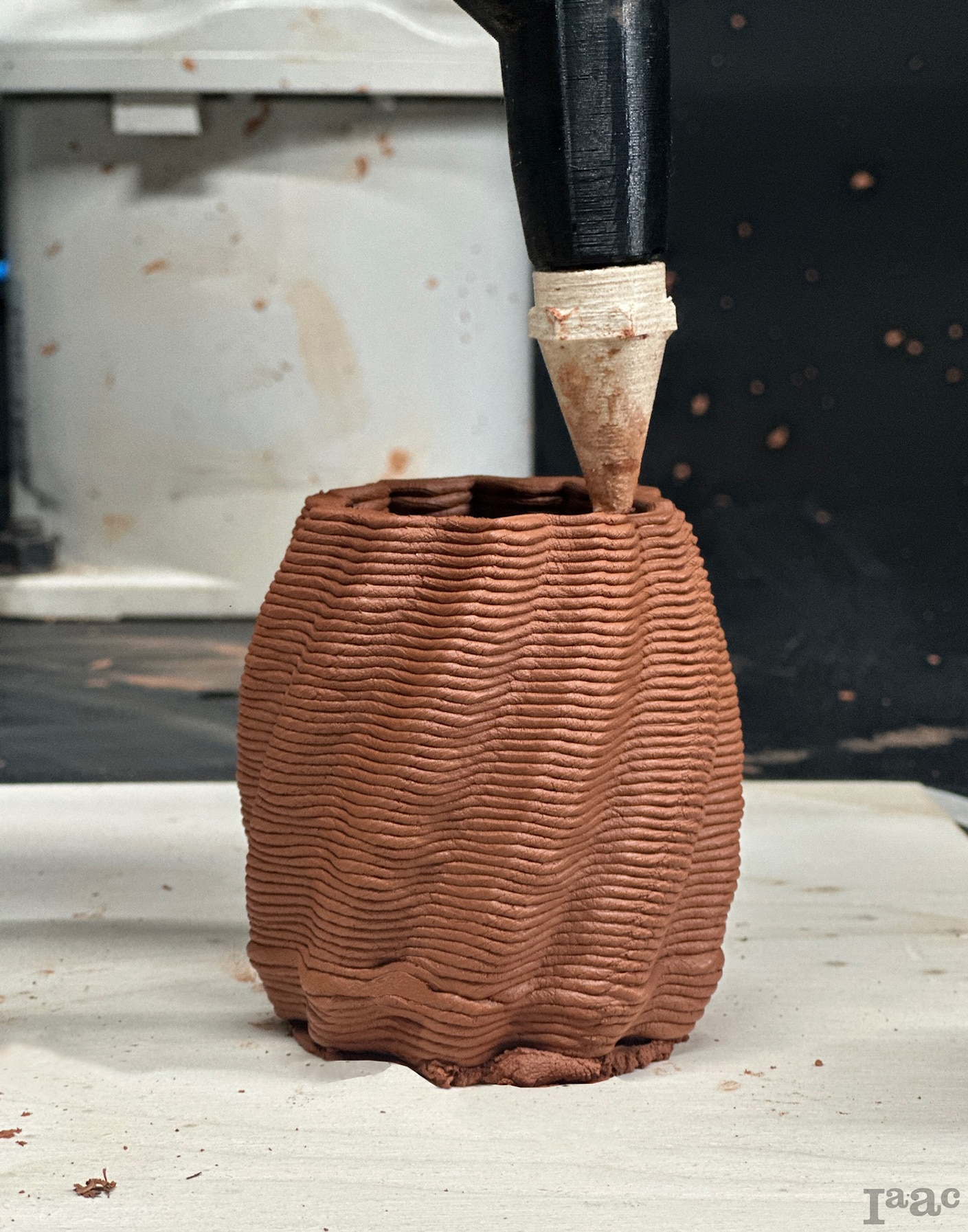
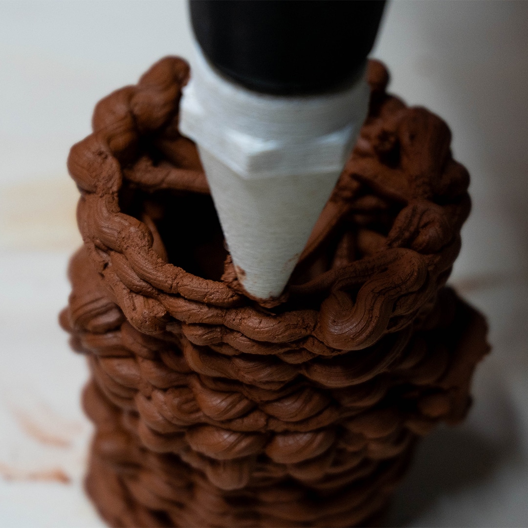
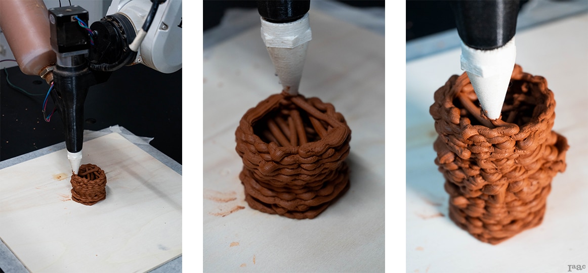
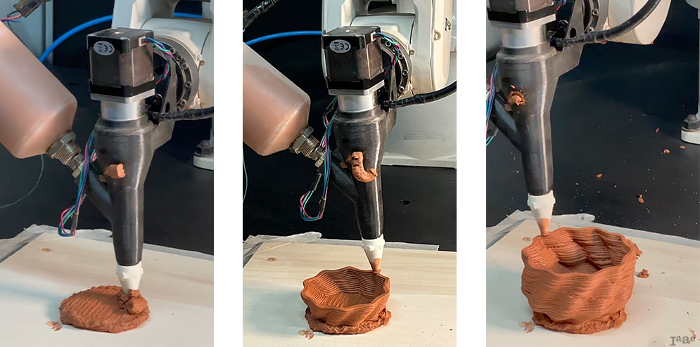
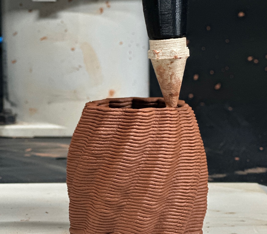
BioCup – Introduction to ABB Robotics
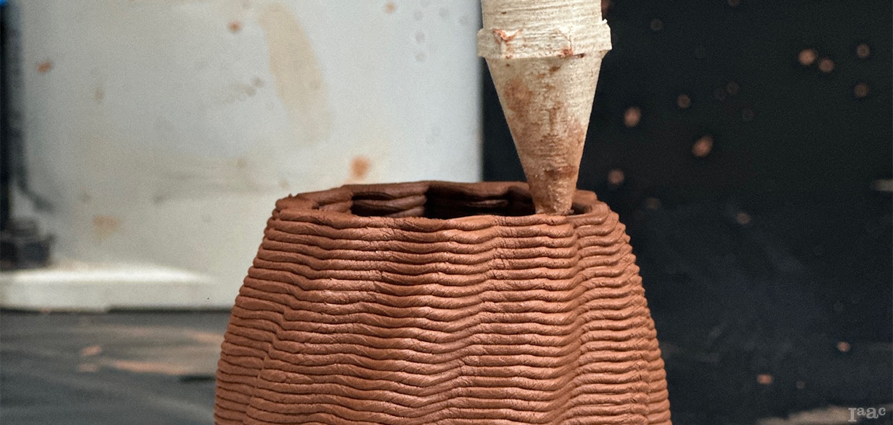
Project Description

First Sample
In the first sample, we had some issues with our first example since we did not approach the model as a system of external lines, which resulted in the incorrect creation of many lines. The way the cartridge is filled is important because too many air spaces can lead to the formation of clay bubbles, which would undermine the design.
Second Sample
In the second sample, we addressed the issues from the first example by adjusting the lines and layer height, but increased the printing arm speed from 15% to 38%. This change caused our design to collapse. For the final model, we implemented a two-layer base while maintaining the same speed throughout the process.
Fabrication Strategy

We optimized project geometry in Grasshopper for the ABB 120 robotic arm, integrating our script with the staff’s to conduct tests for system calibration and establish an effective fabrication workflow.

To begin the process, we prepared the robot by setting up a base for the product, filling the cartridge with clay, and securing it to the end effector. Additionally, prepare and test the digital code to ensure functionality before starting the modeling process.
Speed: 15%
Approximate time: 20m
Material: Premixed clay
Prototype Video

Prototype Pictures