
In the following blog post, we will analyse the development of the concept of our project carried out in Workshop 2.1. Team Collaborative Workflow and Modular System Development Guide, in which a Rotatory Gantry structure is proposed for the flip-type movement of a robotic arm.
AIRFLIP – Rotary Gantry System for Small-Scale Cobots
Overview
The initial idea and proposal for this project was to develop or propose an approach to how we can generate a flip somersault-like movement with a robotic arm, for which we researched on the internet about external axes or gantry systems. A gantry robot is a type of industrial robot, an automated piece of machinery applied in manufacturing or production, that utilizes a robot arm that is mounted either overhead on a rail system or a frame. In the gantry system, the beams hold up the robotic arm, creating an inflexible, stable structure. This arrangement allows gantry robots to move along the three linear axes: X, Y, and Z. They refer respectively to, horizontal movement from left to right, horizontal movement from the front to the back, and vertical movement up and down.
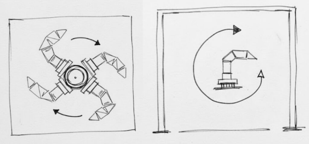
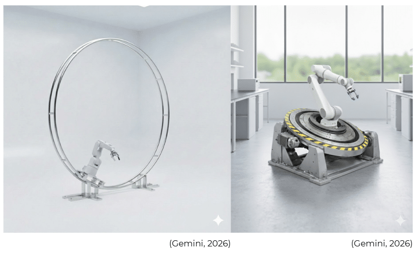
After analyzing these ideas, we decided to make some sketches about what would be most appropriate to implement for a cobot. First, we came up with a system that implements a rotating wheel system, which through guide rails allows the robot to move through that space. The second idea was to implement a structural system that elevates the robot, which also has a central rotary axis that allows it to perform the flip. We were able to visualize these sketches thanks to AI tools that allowed us to develop these images.
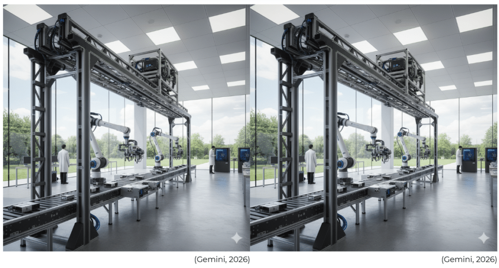
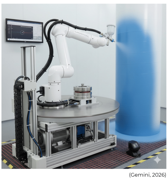
After analyzing these ideas, we determined that the best approach to achieve this movement would be by implementing a Cartesian gantry system, since the previous ideas are less viable and more complex to develop. This project presents a 7th-Axis Rotary Gantry (External Axis) engineered to transcend the workspace limitations and kinematic constraints of compact collaborative robots. While cobots like the Universal Robots UR3e offer industry-leading precision, their 500 mm reach and fixed base often lead to kinematic singularities—mathematical points where the robot loses a degree of freedom and cannot move in specific directions—disqualifying them from large-format or complex industrial tasks.
Core Innovation: Our solution integrates the UR3e onto a rotary Robotic Transfer Unit (RTU). By introducing Kinematic Redundancy, we decouple the robot’s motion from a static base. This “Workspace Multiplier” allows the system to bypass singularity zones (such as wrist alignment or elbow lock) by dynamically rotating the base. This ensures the robot can access areas and zones that are normally inaccessible due to the robot’s inherent singularities, maintaining continuous, fluid motion throughout the entire process.
Application Focus: This proposal is specifically designed for artistic applications such as wall painting. The implementation of the gantry system would enable significant reductions in time and labor costs. With the gantry, the robot can reach numerous zones at angles that would be impossible to achieve without it. Additionally, it allows the robot to move with ease—moving up, down, rotating, and positioning itself according to specific needs—providing unprecedented flexibility for large-scale artistic work.
Getting Started
Prerequisites
Hardware
- Robot: Universal Robots UR3e (e-Series, Polyscope 5.x+).
- Actuator: Industrial AC Servo Motor (Mitsubishi MELSERVO-J4 or Panasonic Minas A6 Series) with IP65/67 rating to withstand paint particulates and overspray.
- Transmission: High-precision, low-backlash Planetary Gearbox (100:1 ratio).
- Media Interface: Industrial Slip Ring rated for Gigabit Ethernet (Profinet/EtherNet/IP) and high-pressure pneumatic supply.
Software
- URCap for External Axis integration and kinematic synchronization.
- Communication Protocol: EtherNet/IP or Modbus TCP for real-time motion handshaking.
Installing
- Mechanical Integration: Mount the UR3e onto the rotary platform. Ensure the center of mass is aligned with the gantry’s axis of rotation to minimize inertial load on the servo drive.
- Driver Configuration: Configure the industrial servo-drive to operate as a slave to the UR3e controller via the Fieldbus interface.
- Kinematic Calibration & Singularity Mitigation: Perform a Tool Center Point (TCP) and External Axis Calibration. The system is programmed to use the 7th axis as a “Redundancy Resolver”—if the arm’s trajectory approaches a singularity, the gantry rotates to reposition the robot’s base, keeping the arm within its optimal dexterity range and reaching zones otherwise blocked by joint limits.
Demo Workflow
The system operates using a Coordinated Spiral Kinematic Path:
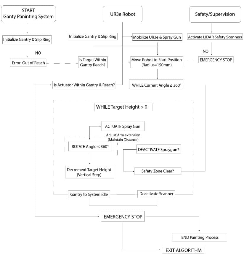
How the Process Works: Gantry & Robot Integration
1. Initialization Phase
At the start, the Gantry and Robot systems initialize simultaneously to ensure hardware synchronization.
- Reach Validation: The system performs a geometric check to confirm the target is within the gantry’s physical workspace.
- Failure: Generates an “Out of Reach” error.
- Active Safety: LIDAR scanners activate immediately.
- Failure: Any detection of abnormal presence triggers an Emergency Stop.
2. Positioning Phase
The robot maneuvers to the initial coordinates to prepare for the first pass.
- Target Offset: Moves to a starting radius of 150mm from the target.
- Redundant Safety Check: A “Double Reach” verification ensures the actuator is within the operational limits of both the gantry structure and the robot arm’s kinematics.
3. Painting Phase (Nested Loops)
The core execution is managed through two nested while loops to ensure full coverage:
Logic Structure
Outer Loop: While current angle ≤ 360° (Complete Rotation)
Inner Loop: While target height > 0 (Top to Bottom)
Execution Steps:
- Spray Activation: Engaging the spray gun.
- Dynamic Adjustment: The arm extension adjusts in real-time to maintain a constant distance from the surface.
- Rotation: Executes movement up to 360°.
- Verification: Deactivates spray gun and confirms “Safety Zone Clear”.
- Iteration: Decrements the target height (vertical step) and repeats the sequence.
4. Completion
Once the conditions of the loops are met:
- Idle State: The gantry returns to its home/idle position.
- Power Down: Scanners are deactivated.
- Safe Exit: The process concludes via a controlled emergency stop to ensure all systems remain locked.
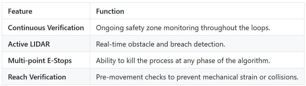
Safety Features Summary
Authors
- Xiomara Alcivar – Mechatronics Engineer (System Design & Robotic Control).
- Subha Tasin Saba – Architect (Structural Design & Surface Optimization).
- Yungsuan Lin – Architect (Spatial Integration & Construction Planning).
References
- Universal Robots: UR3e Technical Specifications & Reach Study
- Mitsubishi Electric Automation: MELSERVO-J4 High-Performance Servo Systems
- NIST: Safety Standards for Collaborative Robotics
- IEEE Xplore: Kinematic Control of 7-DOF Redundant Manipulators
Credits
- Universal Robots A/S: For providing the collaborative platform and the URCaps development ecosystem.
- Mitsubishi Electric: For the industrial-grade servo technology utilized in the rotary gantry.
- Open Source Robotics Foundation (OSRF): For simulation tools used to validate spiral trajectory planning.
- Gemini AI: For providing architectural logic support, technical protocol drafting, and optimization of kinematic redundancy strategies.
Acknowledgement
- Creation of GitHub template: Marita Georganta – Robotic Sensing Expert
- Creation of MRAC-IAAC GitHub Structure: Huanyu Li – Robotic Researcher
Github Link: https://github.com/MRAC-IAAC/MRAC-IAAC-ArmFlip.git
