Structural Analysis: Where You Splice Is Everything
This section covers the structural analysis work underpinning our reclaimed portal frame project – from knee joint behavior to the critical question of splice placement.

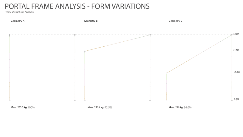
The Portal Frame and Form Variations
Different forms of portal frames react differently under mass and load-
First we compared the mass of different forms as a lighter portal frame means less material and lower center of gravity helps to resist load.
Comparing Maximum displacement under three types of load cases-
1)Gravity
2)Roof load
3) wind load
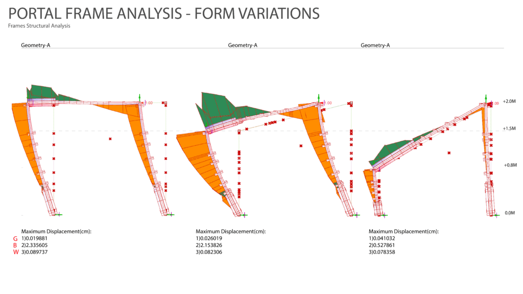
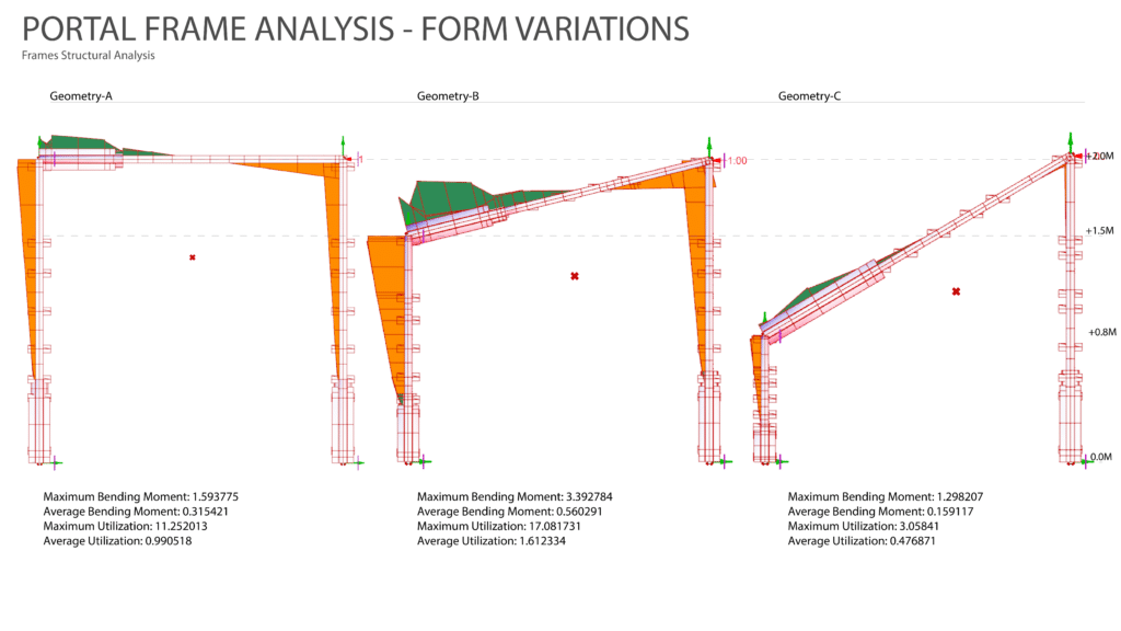
After comparing the Maximum Bending moment and utilization we concluded geometry C works the best.
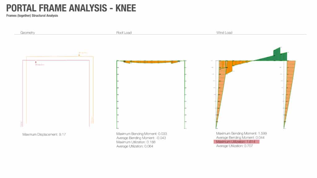
The Portal Frame and the Knee Joint
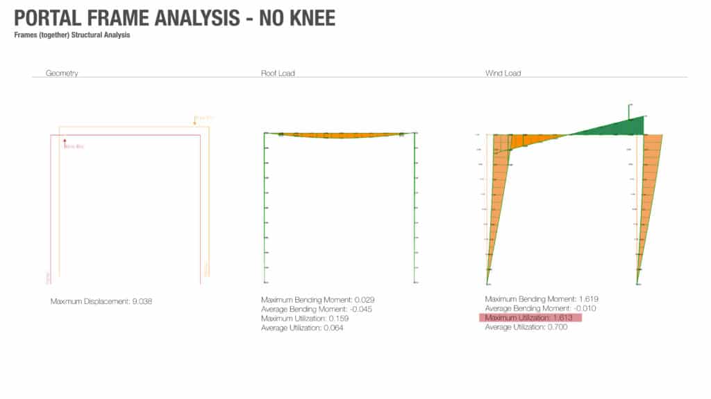
We began by running structural analysis on two fundamental portal frame configurations: one with a full knee joint at the eaves, and one without. Understanding the difference between these two conditions turned out to be one of the most consequential findings of the project.
A knee joint does more than just fill a corner. Under wind load, it stiffens the frame, reduces lateral sway, and dramatically improves overall structural behaviour. In our analysis, the frame with a knee at the eaves achieved a maximum utilisation of 1.614 under wind load, with an average utilisation of 0.707. The no-knee frame performed similarly on paper (maximum utilisation of 1.613) but the distribution of stress across the frame was meaningfully different, and critically, so was the freedom it afforded for splice placement.
Under roof load alone, both frames behaved well: maximum utilisation stayed below 0.19 and average utilisation around 0.063-0.064. Wind load is where the real structural challenge lives, and where the knee joint performs better.
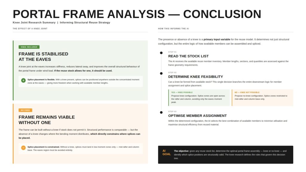
The practical conclusion: if the reuse stock allows for a knee, it should be used. It is not just a structural improvement; it opens up the design space for splicing considerably. However, if the stock does not allow for a knee, the frame can be designed without one if more strict splicing rules are considered.
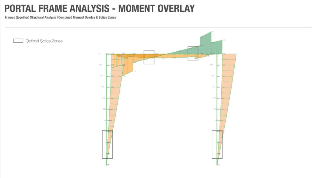
Optimal Splice Zones: Reading the Moment Diagram
With both frame configurations understood, we turned to the question of where to splice. This is where structural reuse gets genuinely complex.
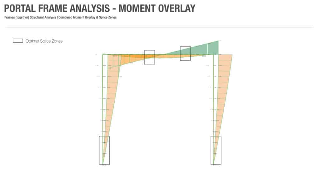
By overlaying bending moment diagrams for both load cases (roof load and wind load) across both frame types, we were able to identify the optimal splice zones: regions of the frame where moment is consistently low, regardless of which load is governing. These zones are marked clearly in our combined moment overlay diagrams.
For the knee frame, splice zones are relatively generous. With the knee absorbing and redistributing stress at the eaves, splices can land almost anywhere along the rafter and column, provided they avoid the concentrated moment region at the knee itself. This flexibility is exactly what you need when working with a varied stock of reclaimed timber in fixed lengths.
For the no-knee frame, the picture is more constrained. Without a knee, the eaves region becomes a peak stress zone under wind load, and splices must stay well clear of it. Viable splice positions are effectively restricted to the mid-rafter and the column base.
Splice Position Changes Everything
To put numbers to this, we ran a direct comparison of three conditions on a mono-pitch portal frame (low column left, tall column right): no splice, splice at maximum moment, and splice at minimum moment.
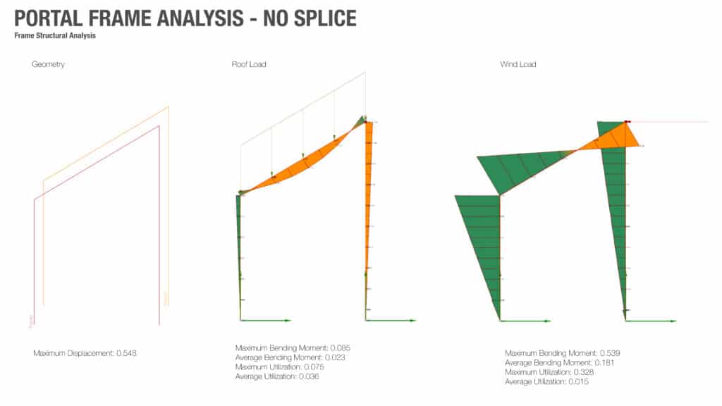
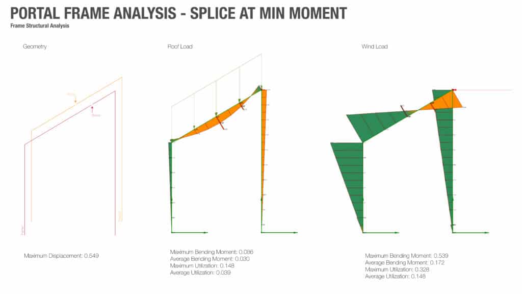
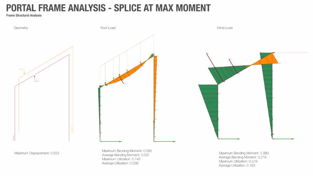
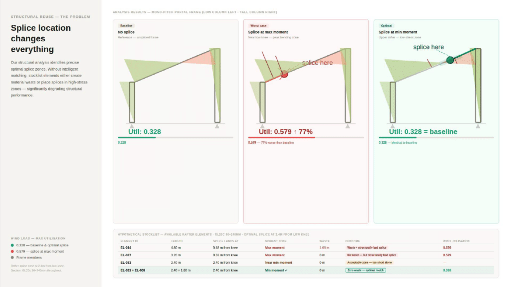
A splice placed at the peak bending zone (near the low knee) nearly doubled the frame’s utilisation factor. The structure was working 77% harder at that point than an unspliced frame. That is a significant structural penalty introduced by a single joint in the wrong place.
A splice placed in the minimum moment zone (in the upper rafter, a low-stress region) produced utilization identical to the baseline. The structure didn’t even register it was there.
This is the core insight of the structural analysis work: the splice is not inherently a weakness. Its impact depends entirely on where it lands.
The Reuse Constraint
This is where the challenge becomes real. When you are working with reclaimed timber, you do not get to choose your member lengths. The stock is what it is (whatever has been salvaged, whatever dimensions happen to be available). Fixed-length elements are a fundamental constraint of the reuse paradigm.
The consequence is that, even knowing exactly where a splice should go, finding stock elements that land a joint in that position (without generating waste, and without compromising section capacity) is genuinely difficult to satisfy all at once. Often the result is a compromise: excessive offcuts from trimming elements to hit the right zone, or a splice that drifts into a structurally suboptimal position because no element in stock lands cleanly where it needs to.
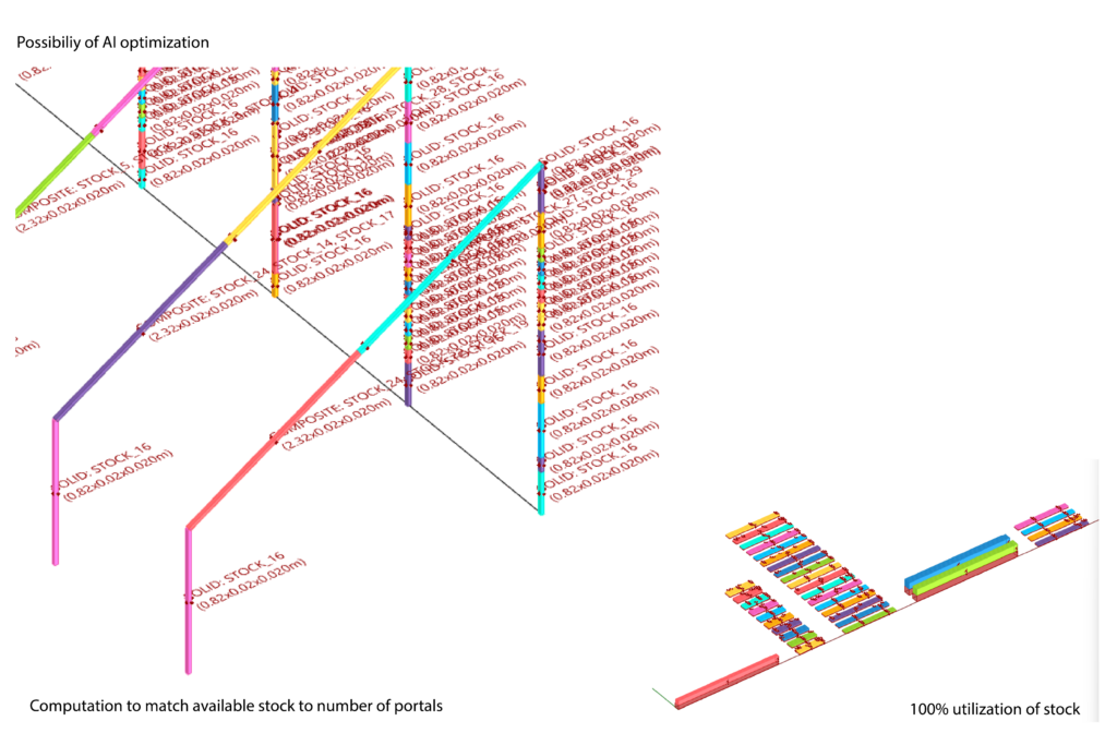
The tension between structural logic and material reality is precisely the problem that the AI-optimized assembly component of our workflow is designed to resolve. The structural analysis doesn’t just describe the problem; it defines the rules the optimizer must work within.
Next: how those rules become inputs for the Grasshopper AI component, and how available stock is matched against frame requirements.
Structural Analysis and AI-Optimized Assembly
From Images to usable stock in Grasshopper using AI Vision
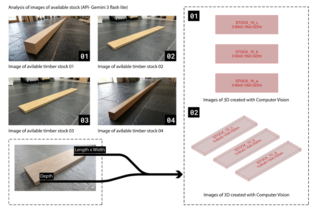
We have developed a workflow that integrates computer vision directly into Rhino to automate the cataloging of reused wooden members. By using a camera feed or point cloud data, we identify each timber piece’s bounding box to extract its actual dimensions (e.g., 0.65m x 0.20m x 0.30m), though we account for a 10% deviation in scale as the proportions remain almost always accurate.
Prompt = “””You are an expert lumber estimator. You are analyzing a batch of images of wood stock. You MUST return a JSON array containing one dictionary for EVERY single image provided. Do not skip or group any images. Each dictionary MUST contain the following keys: – ‘filename’: The exact filename provided before the image. – ‘length’: Estimated length in meters. – ‘width’: Estimated width in meters. – ‘thickness’: Estimated thickness in meters. Return ONLY the raw JSON array. Do not include markdown formatting or explanations.”””
From Images to usable stock in Grasshoper using AI Vision
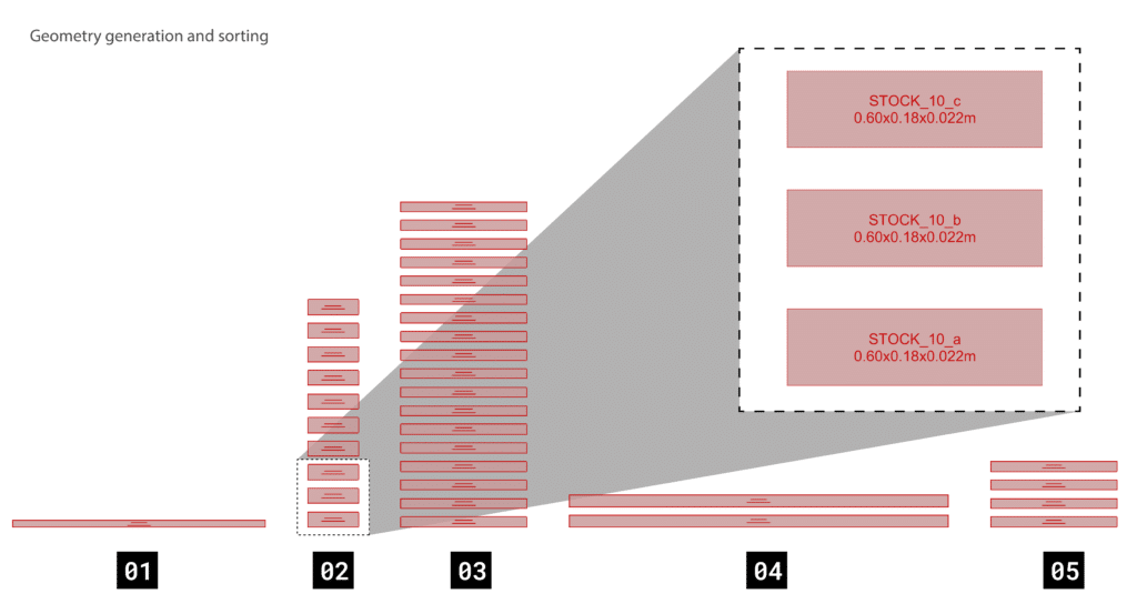
This data is serialized into a digital inventory where the file name itself is stored as the number of available stock for that specific size, such as STOCK_10_a. This allows for a “reverse-fabrication” approach that matches salvaged material directly to architectural geometry.
Location of Splicing
Using Galapagos for form optimization and location of splicing and to generate a dataset for A.I. to understand location of splicing.
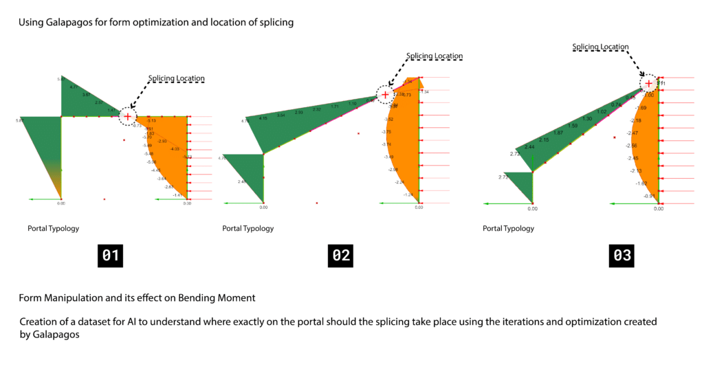
From Stock to From
We have developed a computational workflow in Grasshopper that maps our existing digital inventory of reclaimed timber onto a desired architectural form with a predetermined splicing location. By analyzing the dimensions of the stock, the system evaluates the target geometry and distributes available members based on their best fit. To handle spans exceeding the length of individual pieces, the script integrates a predefined splicing logic, automatically identifying where joints occur and selecting stock combinations that satisfy the structural requirements. This approach ensures that the irregular materiality of the salvaged stock directly informs the final optimized geometry.
Application to larger scale designs