1 | Introduction and Geometry selection
This exercise is based on large-scale geometry to be printed in clay. It is divided into 6 equal segments. After running many tests, we realized that the 90 degrees joinery in the model was very complex to work with (in the creation of the inner and outer shell), and was going to be a difficult print. The following post will explain the failure of this selected geometry in the clay making process.
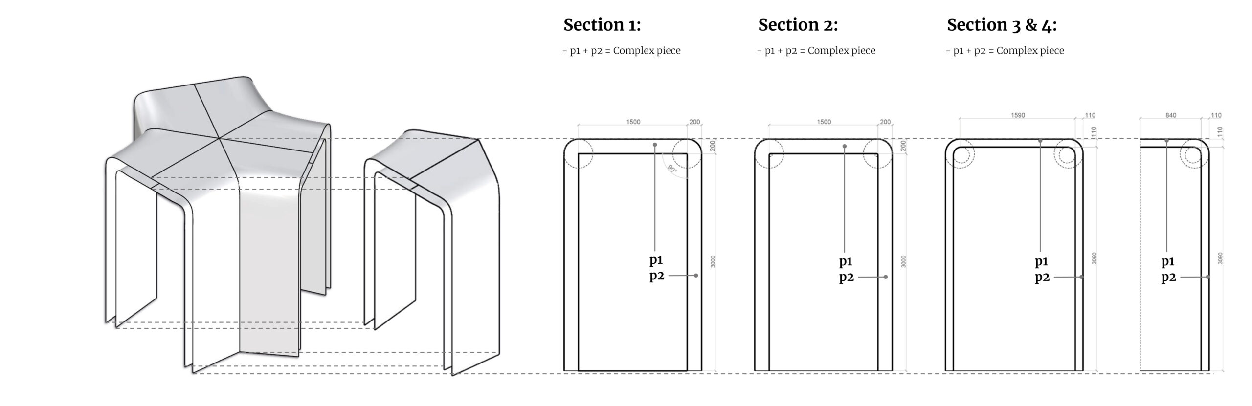
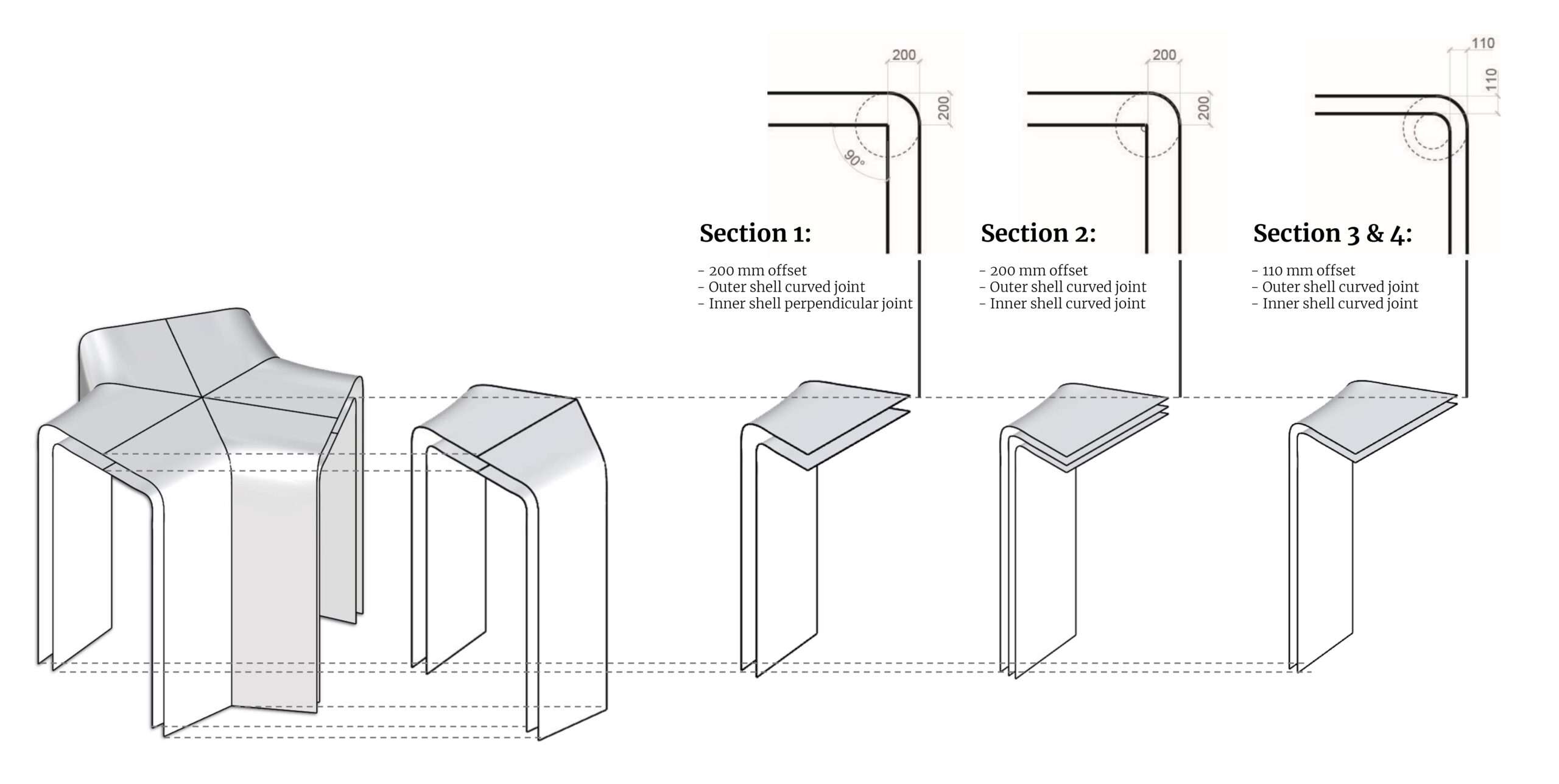
2 | Inner and outer shell
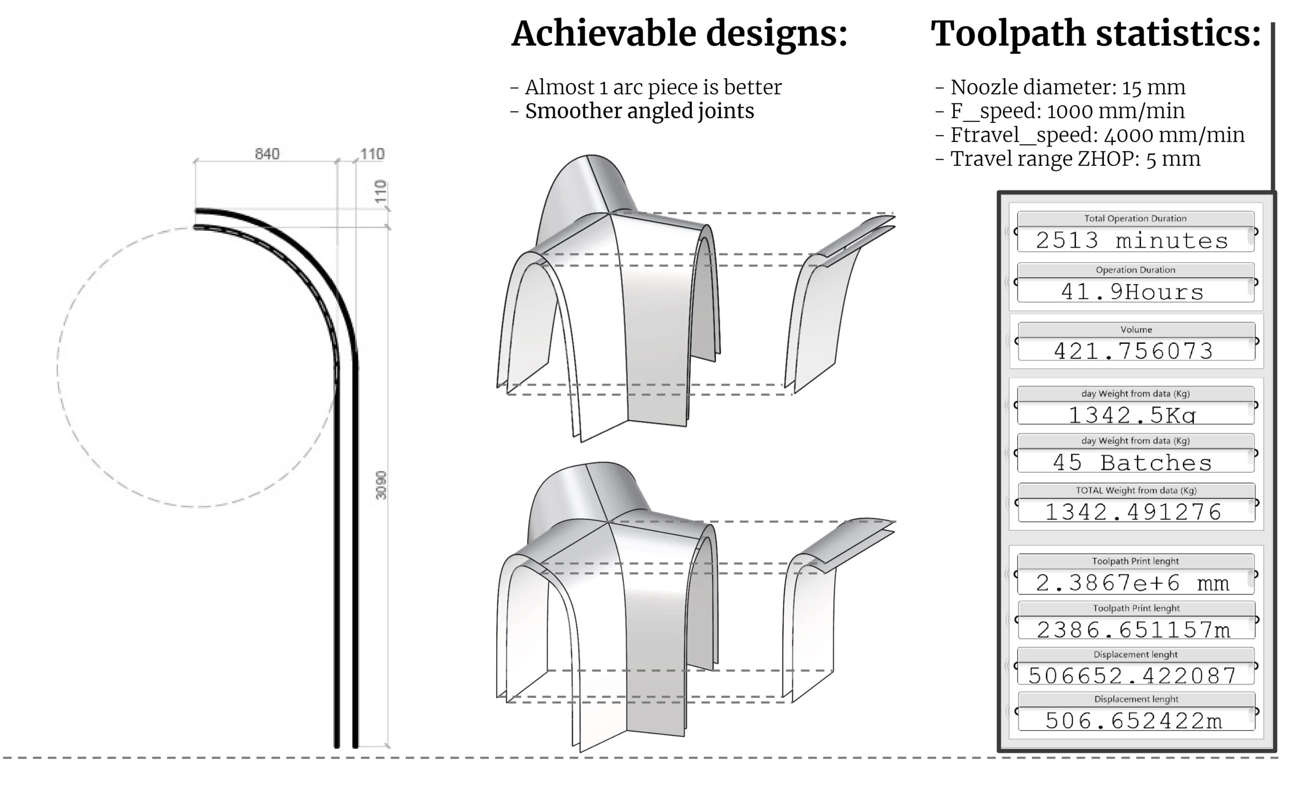
When creating the inner and outer shell of the geometry the group realized that the 90° upper joint angle did not allow to generate a clean and uniform loft of surfaces to be inserted in the script. We had to edit the 90° joint with filet edge and decrease the offset between the inner and outer shelf from 200 mm to 110 mm to make it work.
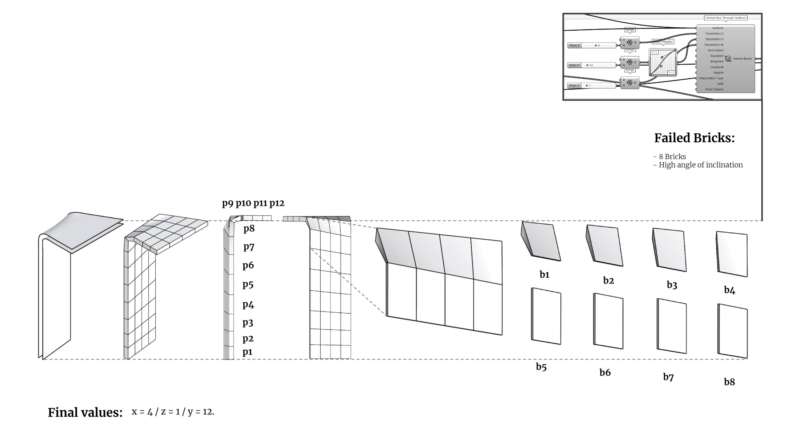
3 | Geometry subdivision
For the subdivide stage of the section, we went through an extensive trial and error process. The final values that were input were as follows: x = 4 / z = 1 / y = 12.
By editing the graph mapper and with a maximum of 12 boxes in Y axis direction, we developed the most efficient subdivision according to the initial inner and outer shell. Even considering the input that allowed for a functioning script, the result was still not the most optimal, due to the complexity of the 90° joint.
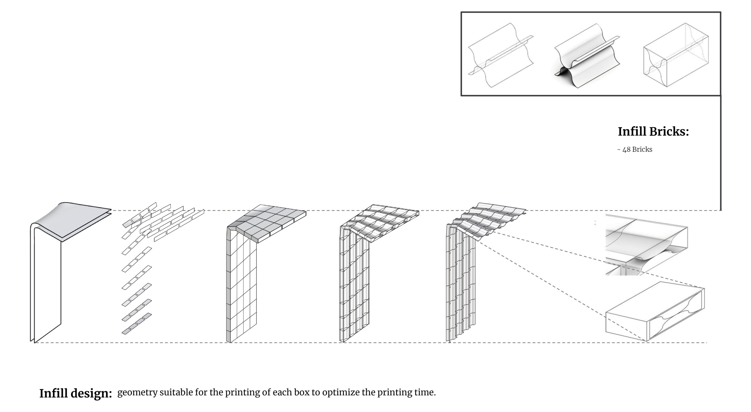
4 | Offset and infill
We made an offset of 15 mm between the outer shell and the inside of each bounding box. We change the design of the infill with a geometry suitable for the printing of each box.
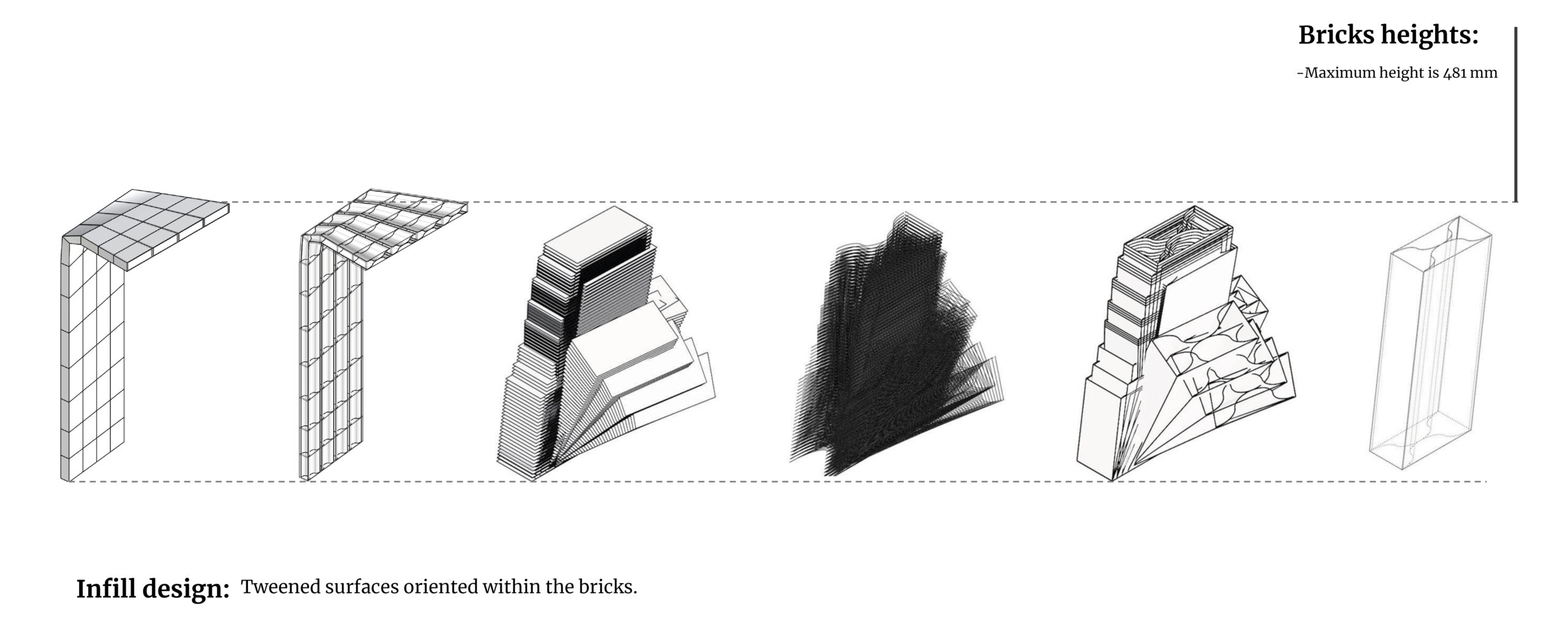
5 | Collect data and Non planar slicing
For data collection, we extracted that the tallest piece to be printed of all the boxes is 481 mm height. We collected the boundary representations/parts of our bricks and set up a plane to understand where the bottom planes of each brick were. After this with the orient tool, we were able to organize all the bricks in the same plane and position. Our maximum brick height is 481 mm.
In this part we used tweening to generate surfaces of all the boxes, creating all of the slicing planes. Our slicing distance is 8 mm, which is 50% of 15 mm (offset box distance). After this we oriented the tweened surfaces within the bricks, to the exact plane of the bricks of our larger geometry.
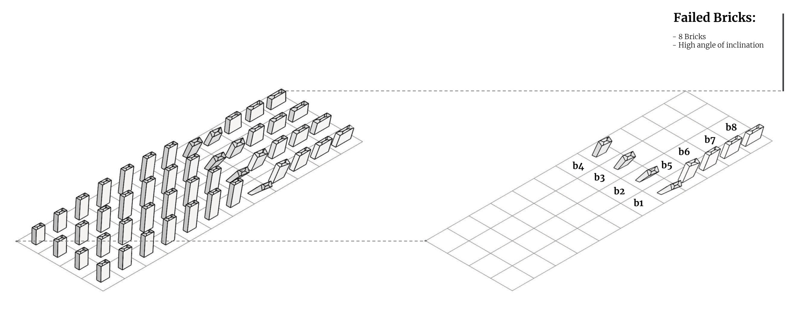
6 | Arrange for analysis and Angle analysis
Now we developed the analysis before printing our bricks. We developed an array with the square component to generate points and determine places for our bricks. The number of squares on the grid were generated from the number of bricks we have in our geometry.
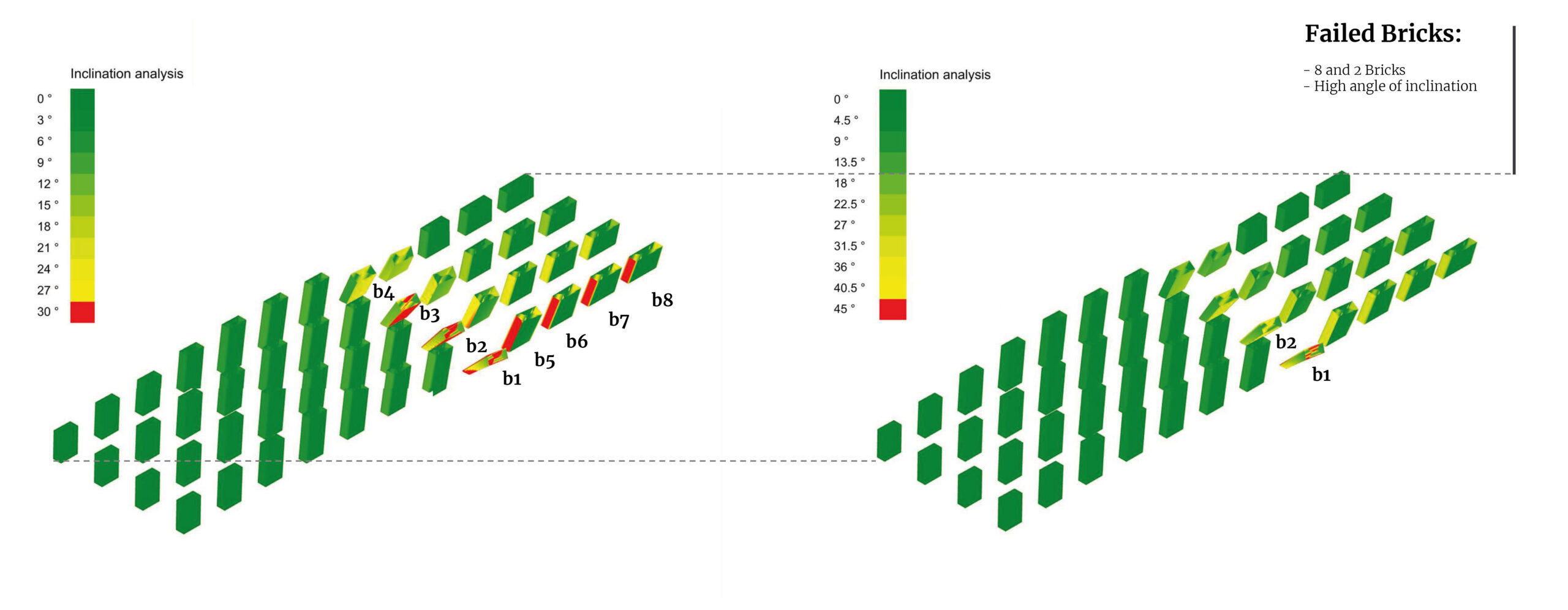
Once we had all our bricks separated we were able to analyze our design with angle analysis. We discovered that 8 of our bricks (when we input 30 % as our max range), had extremely risky angles for construction. If we change the max range to 45%, we only generated 2 bricks with risky angles for construction. Here we realized that the subdivision of this design was not achievable, and we would generate a printing error that may result in collapse.
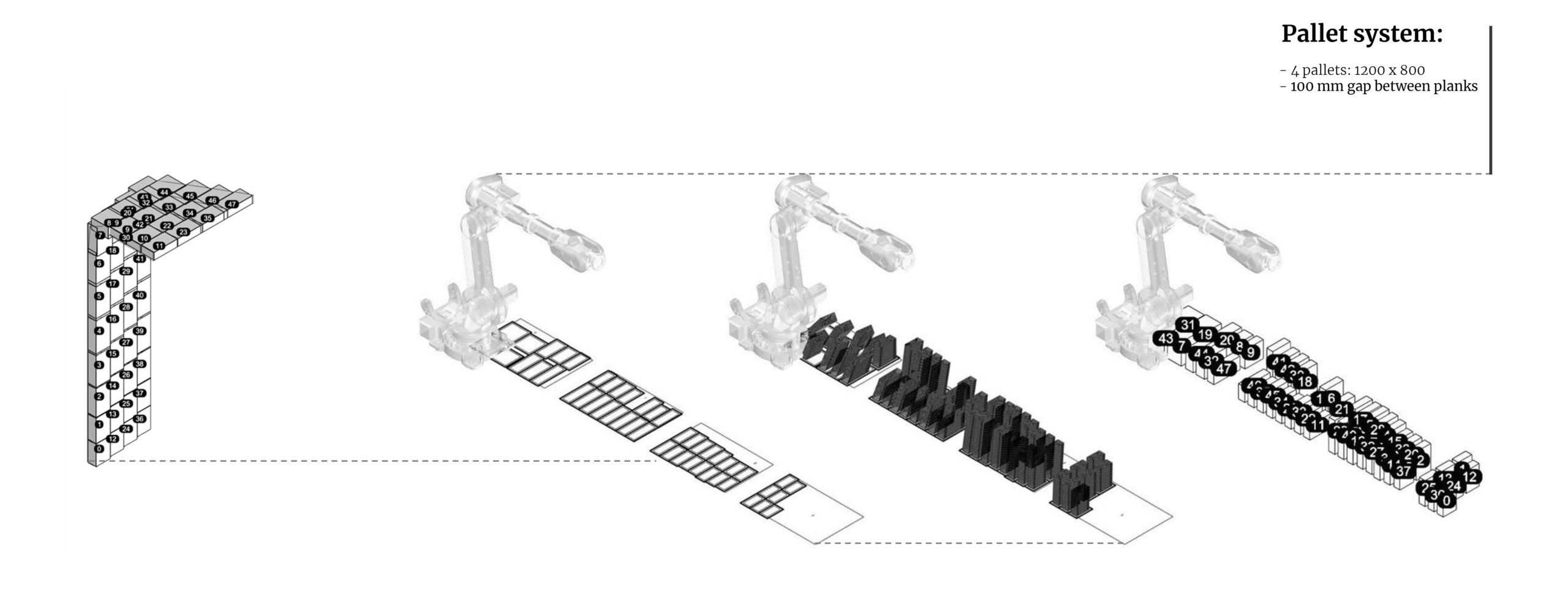
7 | Open Nest and Numbering
We selected the pallet system (1200 x 800 mm). We rationalize our geometry into a simple square. We projected all the curves on the ground with a bounding rectangle to avoid any collision in the printing process. We generated that we would need 4 pallets with a 100 mm gap between the planks. After this we used a transform component to place all the pieces into the 4 pallets. The purpose is to optimize the smallest amount of pallets without arranging them in numerical orde
On this part we wanted to make sure that we can recognize all the bricks inside of our system. All 48 bricks were recognized for this component. After this, we reorganized the pallets data tree to find out where each piece was located on the 4 generated pallets (split tree component).
8 | Robot simulation
We will be using the wasp extruder for printing. First we have to check the TCP of the tool. After this we set up the parameters as follows: speed = 100 / clearance plane = 5 / zone = 1. After this we developed the base for the printing.
9 | Conclusion
The geometry design is not achievable, due to the 90° joint of the arch section. Regardless of how many subdivisions we make, the joint pieces will always yield an angle of inclination that will collapse in the robot printout. To obtain an achievable result it is necessary to smooth the geometry and its inner and outer shells.
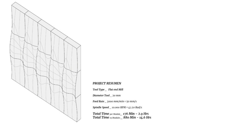
CNC Milling wave wall
1 | Design concept
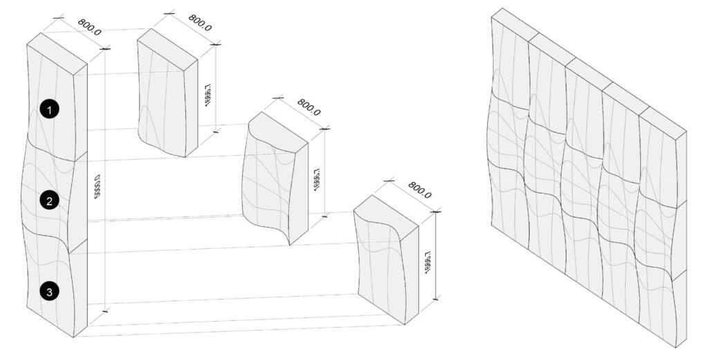
For the milling module, we wanted to experiment with an organic wall that followed uniform waves. We experimented with the milling method on timber.
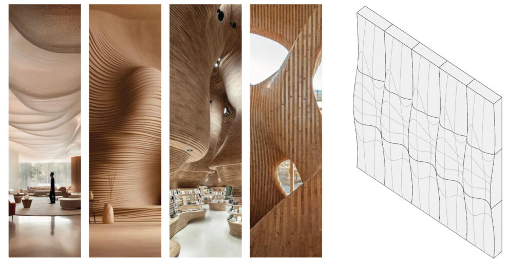
2 | Segmentation Strategy
We broke up our wall into 15 pieces, with the consideration of maximum distances and range capabilities of our tool. Each module is divided into 3 submodules that are 800 x 250 mm, to ensure it fit within the maximum limits of the robotic arm, as well as taking into account the installation, weight, and transportation.
3 | Type of milling processes
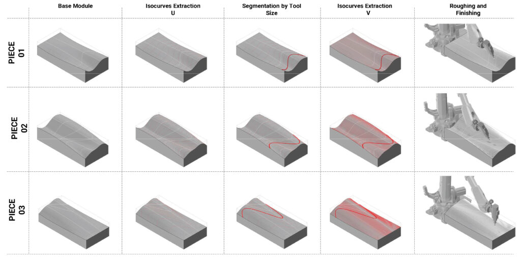
The form of our wall was designed using SubD. For milling, the script extracted several curves along our form to create several points and paths to read what and where to mill. Each point along the curve is distanced at 20 mm to accommodate for the thickness of the milling bit. Through the process of roughing and finishing, we were able to accomplish the smooth finish we desired. In addition, we only required 3 degrees of freedom toolpaths in order to accomplish our form.
4 | Toolpath Analysis
The parameters are pretty consistent throughout the milling of each module: feed rate: 50 mm/s, Spindle speed: 10.000 RPM, Tool diameter: 20 mm.The only difference for the milling process between each module is the time it takes to mill, due to the varying complexities of the geometries.
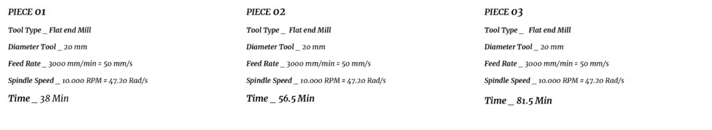
5 | Feasibility Assessment
We plan to align our pieces of wood along the same grain and glue them together to create the large mass that we will subtract from. Each module is divided in 3 submodules, which would give us a total of 15 pieces. Each module would take about 176 minutes to mill, meaning the entire wall to cover would take about 14 hours. Once each panel is complete, we would erect them to the wall on a panel grid system. We may consider changing out the bit to get a smoother finish, as roughing and finishing mills will create different effects.