Balance. Structure. Flow. Essentials in design and in life. Through an exploration of these concepts we have been able to create this cantilevered space with more complexity than what meets the eye. Modular 3D printed components give our Mobile Cabin the capacity to be placed or removed at any time. Through the usage of the CNC machine we have created both the base and topography of our model leaving the flowing laser cut waffle cover to bring everything together. We invite you to explore our process and let your imagination bring this concept to life.
Concept Development
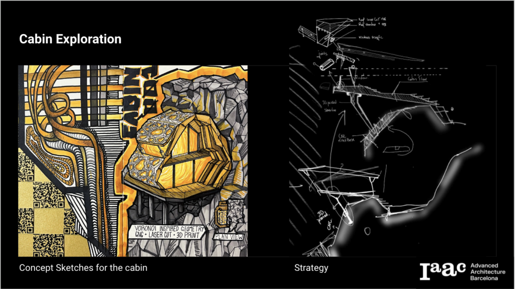
The concept of our cabin design revolves around mobility. Prefabricated elements allow for increased adaptability in the architectural world. Although we imagine our cabin cantilevering off a cliff, the adjustable 3D printed foundation clips allow for it to be moved to any other site.
Our exploration features three main fabrication methods, each applied for a different element of our cabin design. These include the 3D-Printed foundation clip, CNC Milled Floor Plate and Base Topography, and a Laser-Cut Envelope.
WEEK 1 | 3D Printing
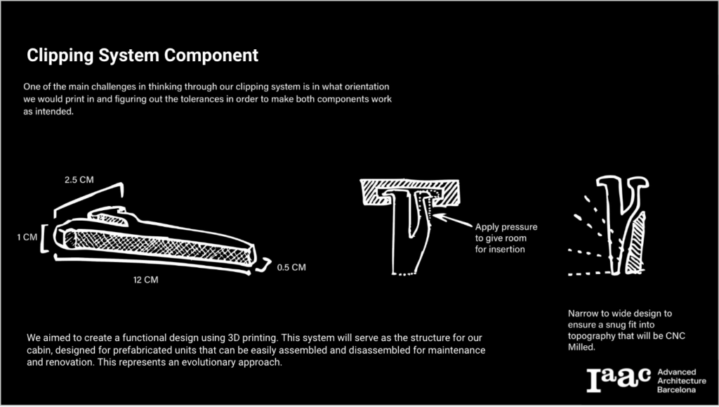
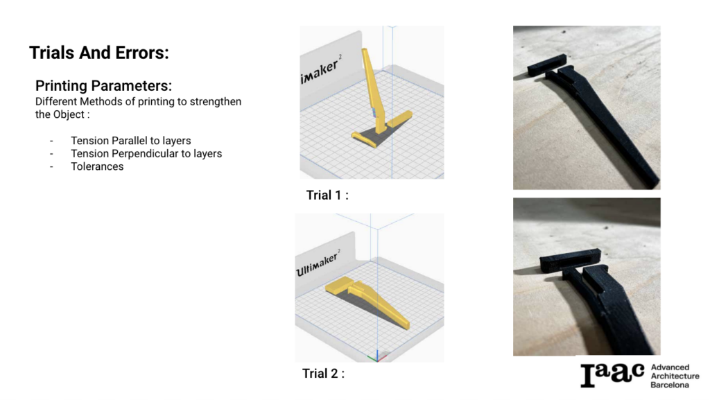
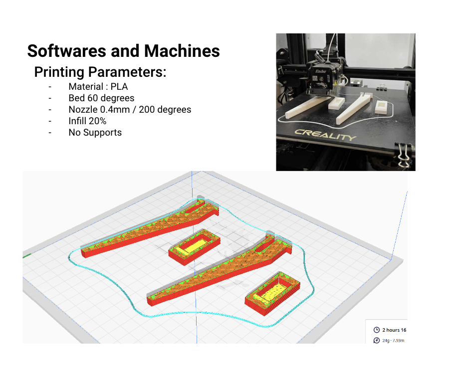
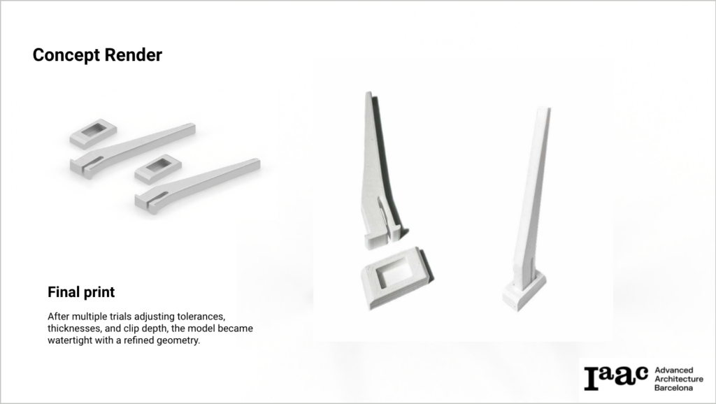
The 3D printing process for the clip involved numerous iterations, refining the design with each step. First, we explored different print orientations in an attempt to manipulate the strength of the clip based on the direction of the filament layers. Next, adjustments were made to the tolerances to ensure the clip fit securely and functioned effectively. Fine-tuning these tolerances was essential in achieving a balance between a snug fit and ease of use, enhancing the clip’s performance in its intended application.
WEEK 2 | CNC Milling
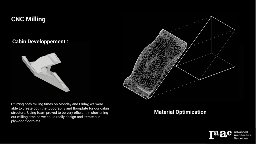
The CNC milling machine was used to model both the floor plate and base topography, each approached with distinct fabrication strategies.
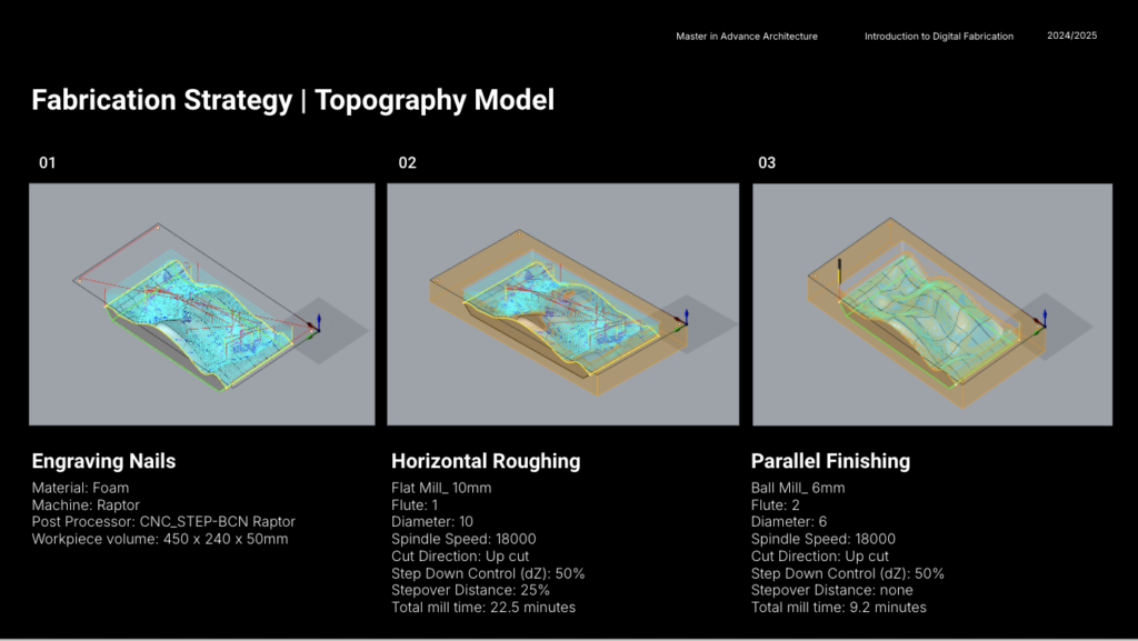
Plywood was initially selected for the topography model, but after advice to switch to foam, the change proved beneficial; foam mills significantly faster and is better suited for this type of model. Given time constraints, we manually created pockets in the topography to accommodate the 3D-printed clips and the stand, though the original plan was to use a pocketing strategy with the CNC machine. This adjustment allowed us to stay on schedule while still achieving the necessary functionality for the model.
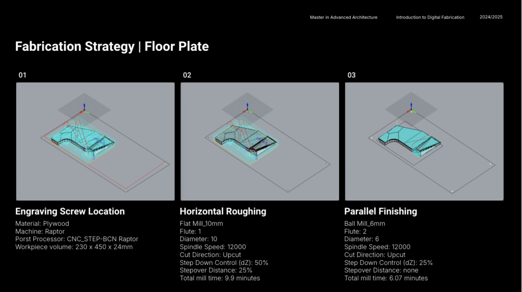
The fabrication strategy for the floor plate combined horizontal roughing with parallel finishing. On reflection, we identified several improvements:
- Flat End: Horizontal roughing alone would have sufficed to achieve a flat surface, making parallel finishing unnecessary.
- Larger Stepover: Increasing the stepover could have created more precise stairs, enhancing their definition at a small scale.
- Pocketing Behind Stairs: Utilizing a pocketing strategy for the recess behind the stairs would have added clarity and depth to this feature.
- Selective Boundaries: Defining the exact bounds of the floor plate model, rather than the entire surrounding square, would have reduced fabrication time significantly.
WEEK 3 | Laser Cutting
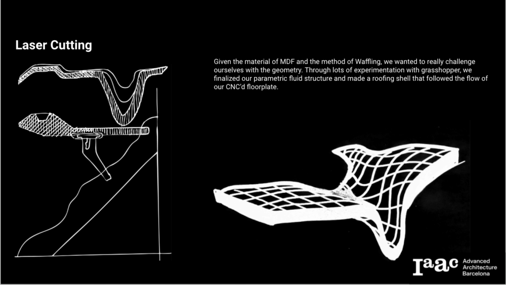
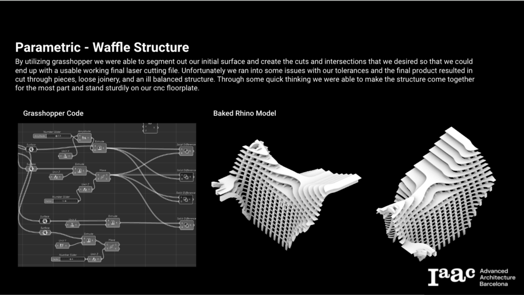
Grasshopper was employed to configure the cabin envelope geometry and generate a waffle cut pattern. The resulting file was then flattened and used as a guide to cut 4mm MDF.
FINAL CABIN ASSEMBLY
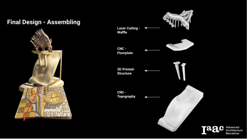
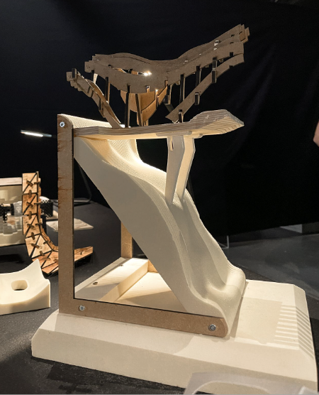
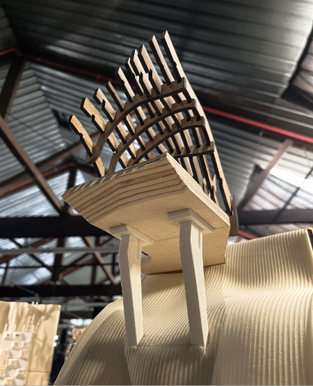

Final cabin assembly photos

