During the first term of the Master’s program, we took a class called “Advanced Digital Tools,” which focused on exploring all the functions and potentials of the software “Grasshopper.” This blog post aims to showcase some of the works developed during the course, illustrating both the processes and results.
Same code, variations of parameters
The first assignment aimed to produce various objects derived from the same code by altering its parameters. The goal was to demonstrate the influential role of parameters, capable of transforming the entire model and generating novel shapes. The results are illustrated in the following picture.

Image o1: Sequence of furnitures generated using the same code, but changing some parameters.
For the two first pieces, the only difference is the value of the X from the first construct point. The green cushion code is not shown in the picture below.
Image 02: Code used to generate the two first previous models
For the other 2 pieces of furniture, the sequence of components are shown below. In order to create a backrest, some parameters were changed from the previous sequence to create a new profile shape. Also, the new design is a result of the rotation of the Revolution axis. The angle of the Rotate parameter was connected to a Multiplication component in order to balance the rotation axis and place the object over the xy plane.
Image 03: Sequence of parameters from last piece (that resembles a table)
Inspired and moving attractor
Another assignment focused on taking some building, furniture or installation and develop something from it, but making sure to use the component Attractor Point. For this exercise, the reference that I chose was the Coachella Installation “Sarbalé Ke” designed by the architetural office Kere Architecture;
Image 04: Axonometry of Sarbalé Ke (Image from the website of the office)
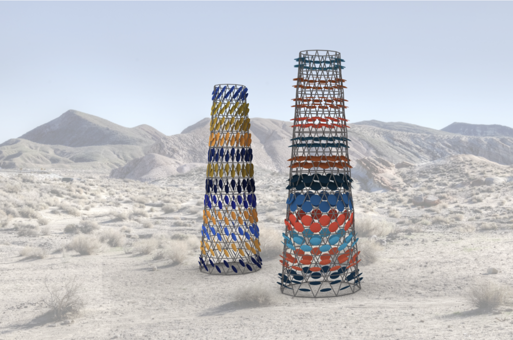
For this model, it was used the component “Triangle Panels B” (from Lunchbox plugin). The resulting surface was connected to the “Grid Structure” command to have the structure – which thickness was generated using “Pipe” command. The attractor point was done by using “Point on Curve” command along with “Circle”, as the initial idea was to have the panels following the Sun. With the use of “Area” command, it was extracted the center of the triangles. Then, it was used “Vector 2P” to connect the attractor point to the center of the circles created using “Circle CNR”. In sequence, “Boundary Surface” was used. “Partition List” command was used in order to divide the list of circles and organize how they would be painted (one color for each row of 25 triangles). The final result was rendered here it is:

Image 05: Rendered image of the model placed over a desert image.
the twist
The final assignment centered on developing a video by animating a number slider. The objective was to visually convey a process, allowing the video to speak for itself without requiring the viewer to examine any underlying code. For this project, we chose to animate a simplified version of the shape of “The Twist,” a building designed by BIG. The exercise was a collaborative effort, and I collaborated with Ludo Poot on this task.

