
(Either that or a cool edgy name too.)
As for a very simple concept: The idea surged from the need present for some of the people from the neighborhood. Many students struggle with finding good and affordable food at Barcelona – so, naturally, they resort to cooking themselves.
Yet. for the last few months, some of the groceries got their prices considerably increased, which makes people leave some of the groceries behind in favor of getting the most important ones.
Some fresh spices, basil as an example, cannot even get compared to their dried counterparts. Yet, the price, follows the same principle. The sollution found was to start planting spices at home in little vases – so that we allways have them available – and for the best price.
From there, the problem situation arises: Most of us are not home for the entire day, and we don’t actually got the spare time to be watering different plants on different days – as well as to be evaluating the soil situation to assess if they should be watered or not.
From there: it was very obvious. We needed something that could do this for us. Automatic irrigation is nothing new. It is common both for household and agricultural aplications for quite some time now. But it would be interesting to understand how it would be possible to develop such a system while also producing something that is usefull and accessible for people arround.
COMPONENTS
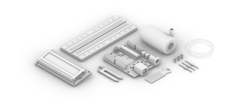
The components selection was very straightforward.
- 1. Arduino Board;
- 2. Breadboard;
- 3. Soil moisture sensor;
The first three components chosen were the most obvious ones for this application. Next, I decided what the circuit would do once it assessed that the soil is dry and the plant is thirsty. So…
- 4. Aquarium 5V pump;
- 5. Aquarium flexible hose;
The system would automatically irrigate the plant once it is percieved that the soil is not moisturized enough. But, from there, it is obvious that this water must come from somewhere – in this case – a bucket. This creates a problem in itself because it requires to check on the reservatory every once in a while and – as it is rented – we are not able to mess with the house’s plumbing (even though we’re basically only architects and engineers arround here). So, to mitigate this immediate issue:
- 6. LED and Resistors;
- 7. Water level sensor;
A second routine is implemented using the Water Level sensor. It measures the height of the water inside the tank and, once it is empty, it lights up a RED LED light so that to warn the house inhabitants to fill it up once it is possible. The blue light was also added to warn whenever the pump is active.
At this point the system was working – but there was a request for being able to assess how long it has been since the last positive system response – for being able to double check it’s functions in the long run. For that, the last component:
- 8. LCD Panel.
Was added to the final result, finally, allowing the user to check how long it has been since the last watering session.
CIRCUIT
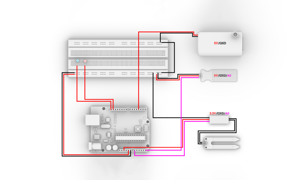
As a summary: the automatic irrigator utilizes a combination of sensors, actuators, and a user interface to efficiently manage the moisture levels in the soil and ensure optimal plant growth. The Arduino UNO orchestrates the entire process by collecting data, executing programmed logic, and controlling the irrigation components accordingly. The result is a smart and automated solution that promotes efficient water usage and plant care.
Arduino UNO Board: The Arduino UNO serves as the brain of the operation, providing a programmable platform to interface with various sensors and actuators. Its role is to gather data from sensors, make decisions based on programmed logic, and control the irrigation system accordingly.
Breadboard: acts as a convenient platform for assembling and connecting the different components of the circuit without the need for soldering. It simplifies the prototyping process, allowing for easy adjustments and modifications.
Soil Moisture Sensor: The soil moisture sensor is a crucial component for assessing the moisture content in the soil. It is connected to the Arduino’s analog pin A0 and powered by the 3.3V output. This provides input to the system regarding the soil’s moisture level, enabling the Arduino to make informed decisions about when to initiate irrigation.
5V Aquarium Pump: The 5V aquarium pump is responsible for delivering water to the plants through a flexible hose. Connected to digital pin D3 of the Arduino, the pump is activated based on the moisture data received from the soil moisture sensor. This ensures that water is supplied only when the soil moisture falls below a specified threshold.
Aquarium Flexible Hose: The flexible hose is an extension of the aquarium pump and is directed towards the plants for targeted irrigation. Its role is to efficiently distribute water to the areas that require moisture, optimizing the irrigation process.
LED and Resistors: The LED, along with appropriate resistors, can be incorporated for visual indicators. The blue one signals the activation of the pump while the red one indicates the low levels of water in the reservatory. The resistors are essential for limiting the current flowing through the LED, protecting it from damage.
Water Level Sensor: The water level sensor, connected to analog pin A5, monitors the water level inside the reservoir. This information is valuable for preventing the pump from running dry, ensuring a constant and adequate water supply for the irrigation system.
LCD Panel: The LCD panel, connected to various digital pins (RS: D9, EN: D8, D4: D7, D5: D6, D6: D5, D7: D4), serves as the user interface. It displays information such as the time elapsed since the last irrigation check, current system status. This enhances user interaction and provides real-time feedback on the system’s performance – allowing it to run on the DC connector and elliminating the need of constant connection to the computer.
CODE
The code was developed by applying the knowledges acquired in class. The ChatGPT was also a tool used for bug-checking and function revision – more speciffically in regards to the LCD monitor. The code is divided in a series of sections. Those shall be explained as we progress:
//LCD monitor
#include <LiquidCrystal.h>
const int rs = 9, en = 8, d4 = 7, d5 = 6, d6 = 5, d7 = 4;
LiquidCrystal lcd(rs, en, d4, d5, d6, d7);
int ULONG_MAX = 4294967295;
//WaterLevel System:
int levelPin = A5;
int levelvalue = 0; // variable to store the sensor value
int alertPin = 12; // LED that indicates low water level
//Watering System
int motorPin = 3; // pin that turns on the WATER PUMP
int blinkPin = 13; // LED that indicates watering process
int watertime = 5; // Time for watering (in seconds)
int waittime = 1; // how long to wait between watering (in minutes)
//Timer functions
unsigned long starttime = 0;
unsigned long finaltime = 0;
long time = 0;
- The initial inputs are displayed and a series of longs is included for the variables that follow
void setup()
{
pinMode(motorPin, OUTPUT); // set Pin 3 to an output
pinMode(blinkPin, OUTPUT); // set pin 13 to an output
pinMode(levelPin, INPUT); // set Pin A5 to input
pinMode(alertPin, OUTPUT); // set pin 12 to input
starttime = millis(); //mills function sets the count for the timer
lcd.begin(16, 2); //Informs the size for the LCD screen
Serial.begin(9600);
}
- The void setup, so, deffines the inputs and outputs, sets the timer and the serial starts.
void loop(){
int moisturePin = analogRead(A0); //read analog value of moisture sensor
int moisture = ( 100 – ( (moisturePin / 1023.00) * 100 ) ); //maps into percentage
//Timer
int finaltime = millis(); //timeloop
int time = ((finaltime – starttime)/1000); //time since last watering (seconds)
if (finaltime < starttime) {
time = (ULONG_MAX – starttime) + finaltime;
}
else {
time = finaltime – starttime;
}
time /= 1000;
/*Water Level System loop:*/
int levelvalue = analogRead(levelPin); // read the analog value from sensor
Serial.print(“Water Level at: “);
Serial.print(levelvalue);
if(levelvalue < 100) { // Desired water height
digitalWrite(alertPin, HIGH);
Serial.println(” Can I get some attention here ? We will dry out.”);
}
else {
digitalWrite(alertPin, LOW);
Serial.println(” Chill out. Everything is under control.”);
}
/*Water Pump System loop:*/
Serial.print(“Moisture value: “);
Serial.print(moisture);
// LCD Monitor:
lcd.print(“Hum. “);
char moistureStr[5]; // Allocate a char array to hold the moisture string
dtostrf(moisture, 3, 0, moistureStr); // Convert moisture to a string with 0 decimal places
lcd.print(moistureStr);
lcd.setCursor(0, 1);
lcd.print(“Time “);
lcd.print(time / 60);
lcd.println(“m”);
/*Water Pump System loop:*/
if (moisture < 40) {
digitalWrite(motorPin, HIGH); // turn on the PUMP
digitalWrite(blinkPin, HIGH); // turn on the indicative LED
delay(watertime * 1000); // WATERS PLANT
digitalWrite(motorPin, LOW); // turn off the PUMP
delay(waittime * 1000); // 1 SECOND WAIT
finaltime = 0;
}
else {
Serial.println(” It should be fine for now. Check back in a minute”); // comment
delay(500);
Serial.println(starttime);
Serial.println(finaltime);
Serial.print(“Calculated time: “);
Serial.print(time);
Serial.println(” s”);
digitalWrite(motorPin, LOW); // turn off PUMP
digitalWrite(blinkPin, LOW); // turn off LED
delay(waittime * 10000); // ONE MINUTE WAIT
}
lcd.autoscroll(); //Keep the text from the monitor running
}
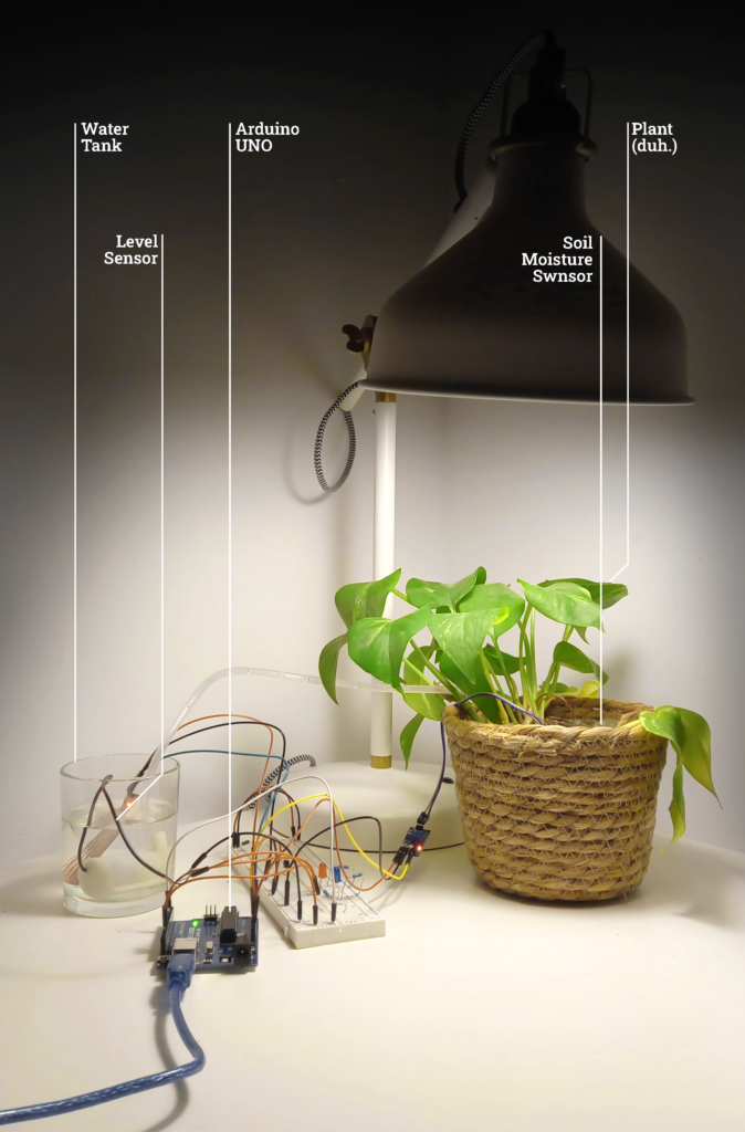
FINAL PROTOTYPE
Inputs
Soil Moisture Sensor: Provides a numerical value as to how wet the soil is. Remaped for 0-100.
Water Level Sensor: Provides a numerical value as to how much water is there still in the tank.
Outputs
Alarms: Once the water levels get too low, a visual alarm will be triggered for the tank to be refilled.
Water pump: If the soil moisture analysis reads lower than 40, the pump will be activated and, through a conductor hose, irrigate the plant for 5 seconds. The procedure is then repeated as long as necessary to adequate the soil for the plant.
LCD Display: Presents the moisture value of the soil and how long (minutes) it’s been since last watering cycle.
Comments
1. The sound alarm intended to work when the water level got too low is way too weak for me to identify it (I am hearing impaired) and had to be removed for the best of the other people in the apartament.
2. A timer and comments are also set to the digital panel, so that the further maintenance for the system outputs get to be executed.
3. After some days of opperation, the two sensors started presenting reading problems. Further examination is required to check on the problem but the leading hypothesis is that the water from Barcelona caused calcification to the metal in the sensors – therefore – damaging them. New sensors were bought from a different provider and, once they arrive, the described issues should be adequatelly sorted out.
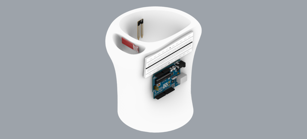
(to the left) A picture of the final prototype.
Video
Video posted on Youtube channel of the opperating system
Next Steps
Expand:
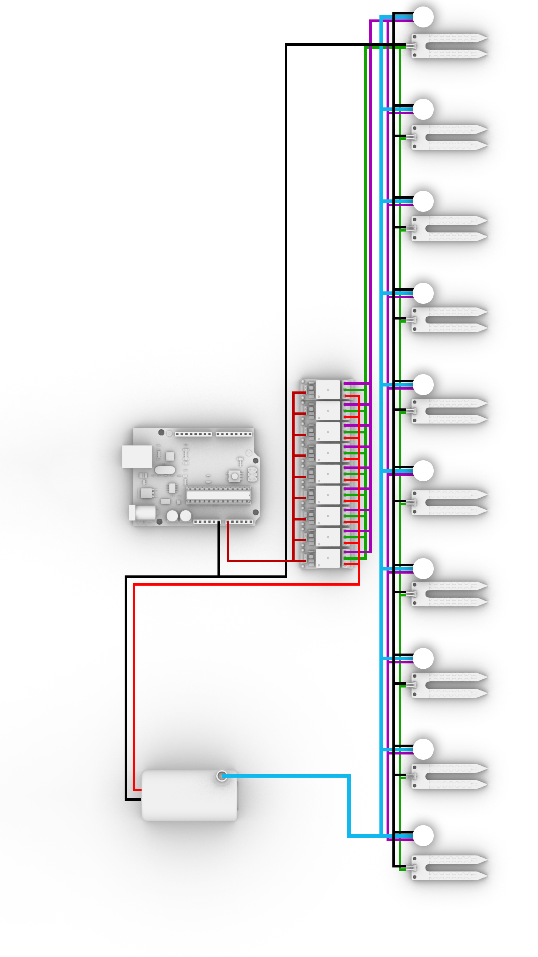
By using multiple sensors and motors, it is possible to configure more complicated routines that respond with precision to different plant species. Furthermore, adding a relay would allow for the system to consume energy only when required, reducing it’s consumption significantly.
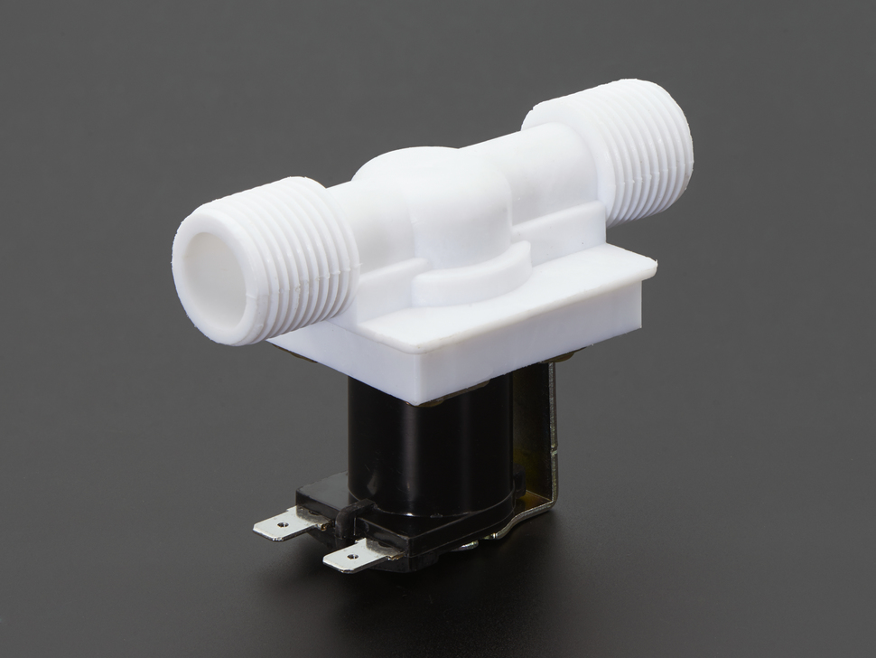
Integrate:
Next is to adapt a Solenoid Water Valve to the system, linked to the water level so that to integrate it to the housing water network and eliminate completely the domestic human activity in this specific case.
Fabricate:
In a householdlevel, the system might be implemented
for individual vases or reproduced for small scale familiar
production with multiple relays and sensors
working in paralel.
