
//Step 1 interest
What interested me in the subject of programming was how complex operations can be decomposed into simple steps. I was impressed by the example of the computer: how the coding system changes at different levels and how multiple combinations come out of binary code. Therefore I decided to study mechanical motion to see how the movement of an object in space and time can be recorded. Professors drew my attention to the “drawing machines” as they allow to trace motion. The main goal was to learn how to deconstruct the task into key stages.
//Step 2 research
Work on the project started with trying to learn more about the idea of apparatus that produce drawings by making lines and marks. History knows many variations of such machines that could be sorted by operation performed and type of movement. In case of this project, were considered the copy method and linear movement, respectively. As a state of art a Pantograph was studied.
Image source: google
Pantograph is handy device for coping and scaling. It has one point fixed to the table, one free point to trace an original drawing and one point that contains drawing device. The challenge was how to use the original principle of how the machine works, but change it for the process to be automated.
//Step 3 set up
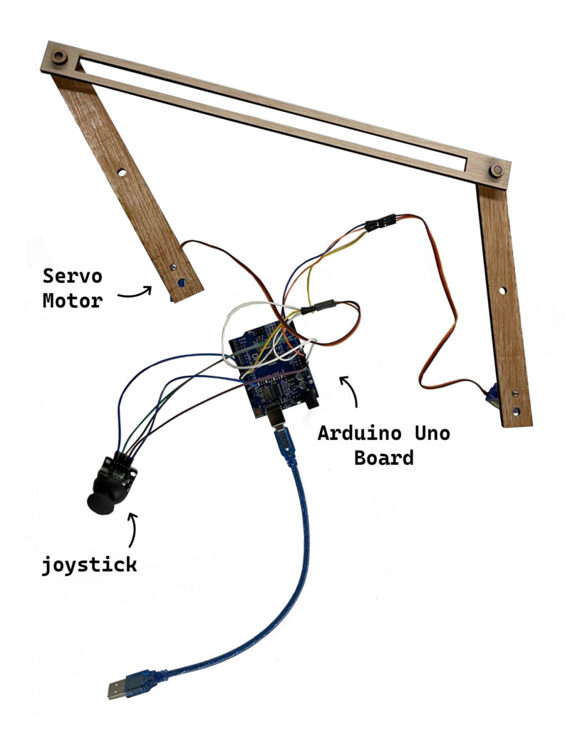
To make the process automated we needed two motors as activators and one sensor to allow human control and set the movement.

The original set contained two stepper motors and one joystick. The condition for the operation was supposed to be speed. However, later it had to be changed to the Servo motor that gives control by degrees.

Stepper motors and joystick were connected directly to the Arduino Uno board.

//Step 4 prototyping
Several tests were made to see which type of movement performs better in set conditions.
As a result of the test option number 3 was chosen since it was allowing more manipulations. At the same time it was possible to move drawing device within central part.
//Step 5 something went wrong
There were several problems with script for the stepper motor. Mostly with how to set conditions properly. Therefore it was changed to the Servo motor. Although the motion and the logic of how it works were slightly different, overall, the motion was recorded to be as expected.
//Step 6 fixing
Original connection was supposed to work with stepper motor and was cut in exact dimensions. Therefore after motor change model had to be adapted to the new connection type.
//Step 7 future steps
To continue working on it it would be preferably to test more angles and see how it affects the motion. Also it would be nice actually record drawing process or connect it to the screen to illustrate o=point movement.
