00 – ABSTRACT
Over the three weeks that lasted the Digital Fabrication Course the main goal was to learn how to develop, model, use the available machinery and prototype designs. For each week a different machine and techniques were used, respectively, CNC Milling, Laser Cutting and 3D printing. Different strategies were applied to achieve the desired result for each step, as for machining there were time constraints and the advantages and limitations that each technique offered that had to be taken into consideration.

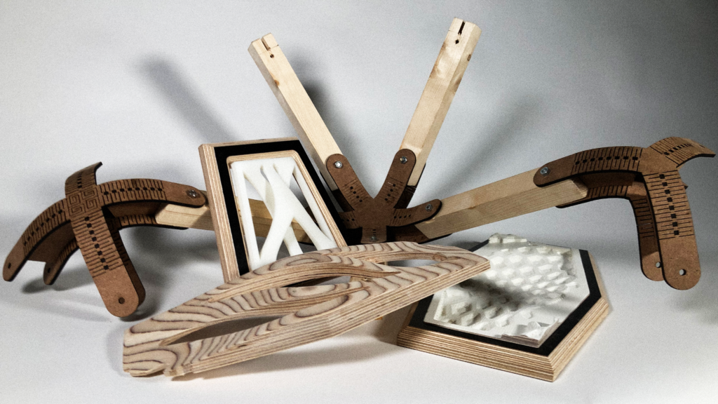
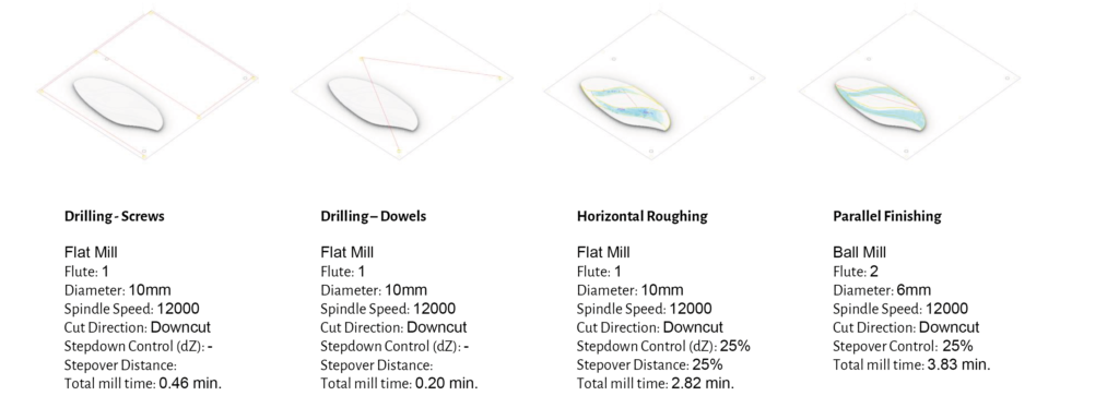
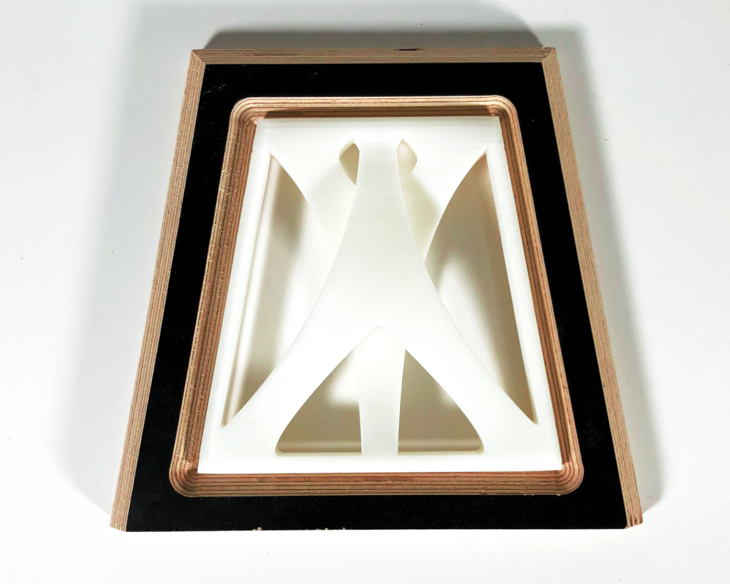
01 – FLIP CNC MILLING
Modeling: Rhino + Grasshopper
Materials: Plywood 30mm
CNC: Shopbot
Postprocessor: SBP
Workpiece volume: 400 x 450 x 30mm
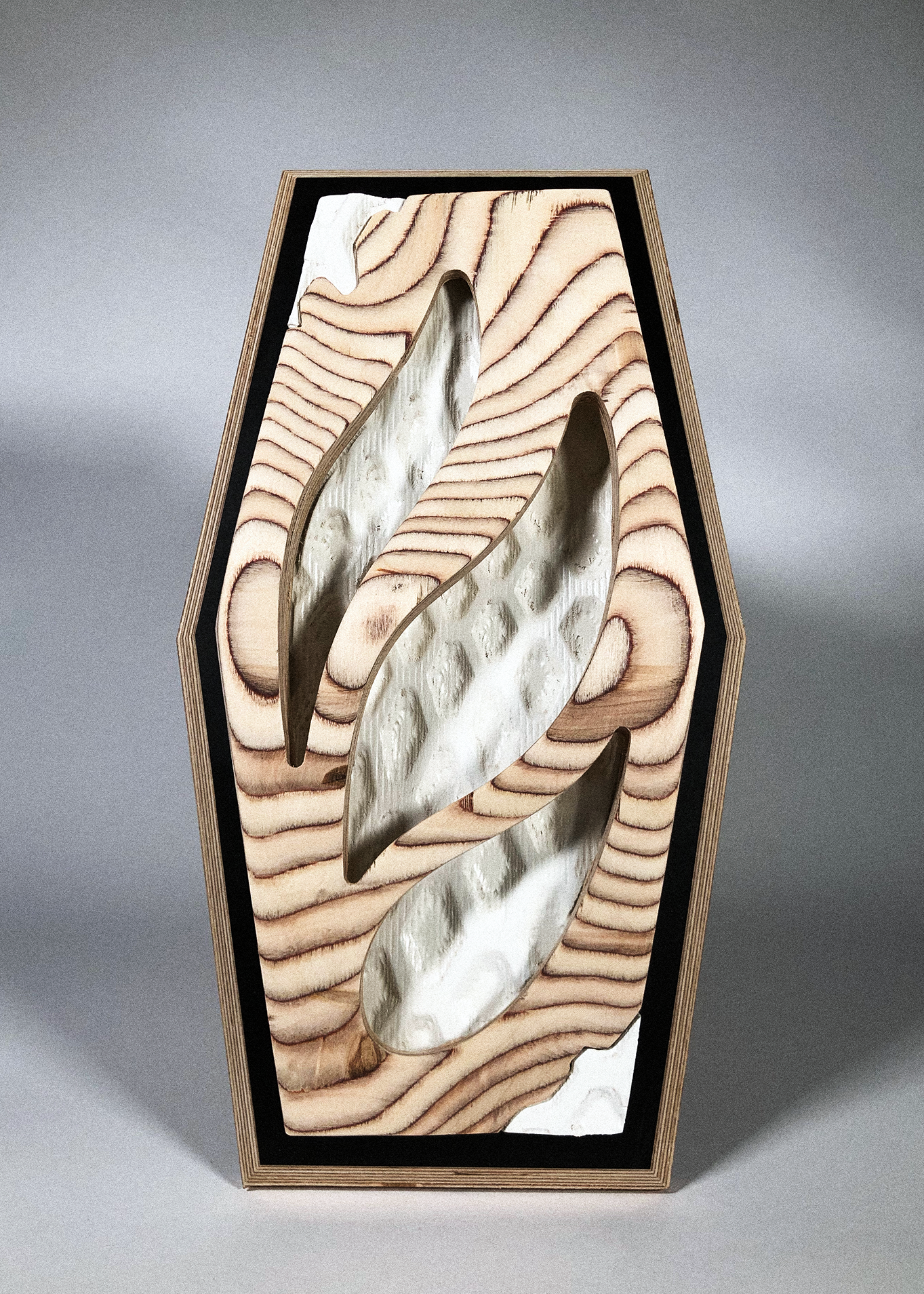
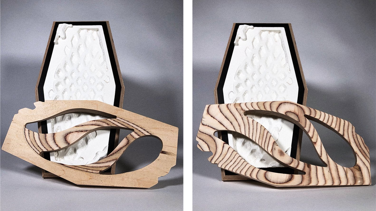
This design’s intention is to explore the possibility of having a concave and convex shell that detaches itself from an underlying texture. This provides new lighting and visual possibilities, as well as an opportunity to explore different and more advanced techinques on the CNC milling machine. It can be divided into two parts, the upper shell with slit-like openings and a bottom texture, achieved by an abstraction form the frame’s shape.
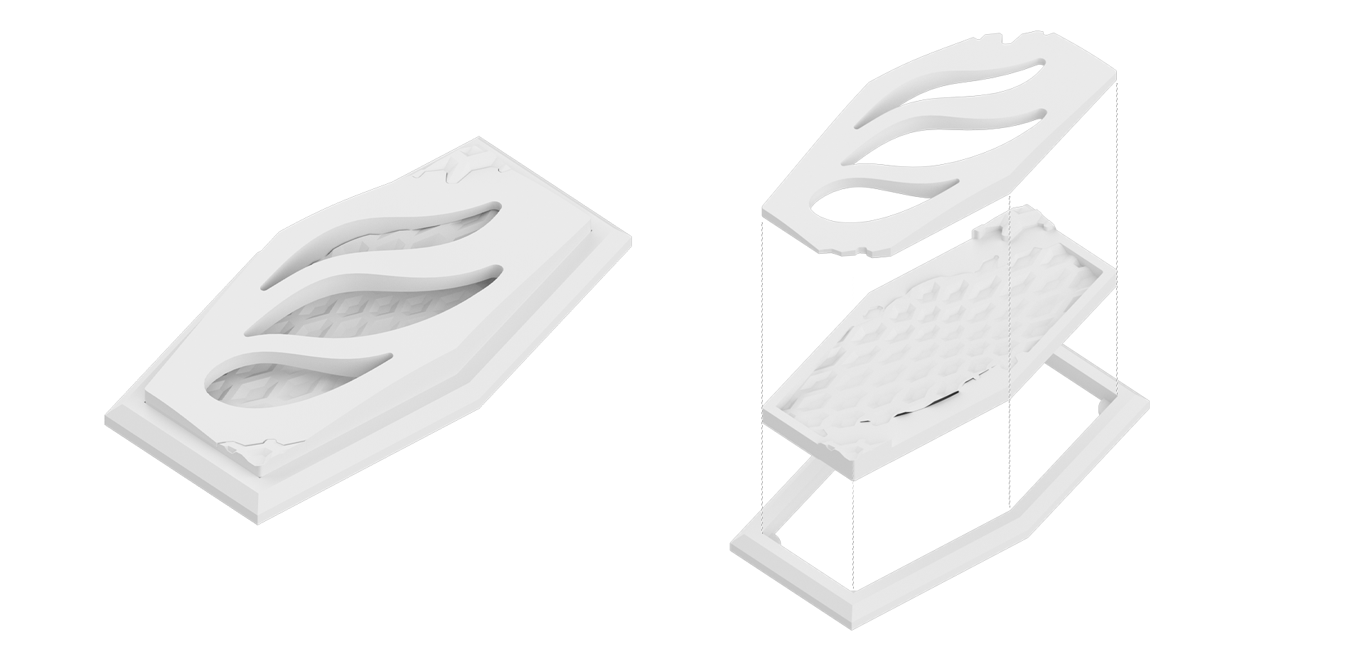
This designs contains milling on both sides of the material, therefore a flip was required. To achieve a more precise operation, dowels were inserted into the surface bellow the plywood, and holes were drilled, so once the flip was attempted, the dowels would serve as a reference for repositioning.
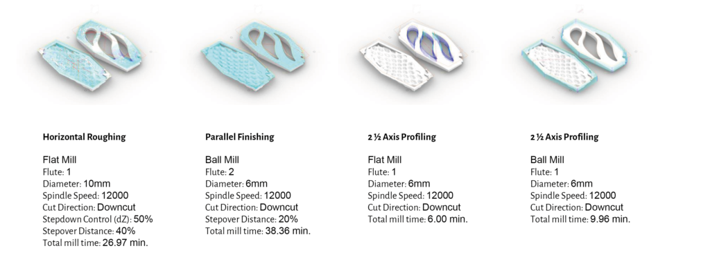
During the milling process, a further profiling was added, it was necessary to achive the correct fit between the shell and texture. Without this adjustment, the two parts would not fit together due to the rounded finishing.
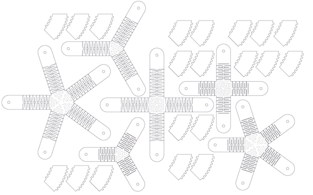
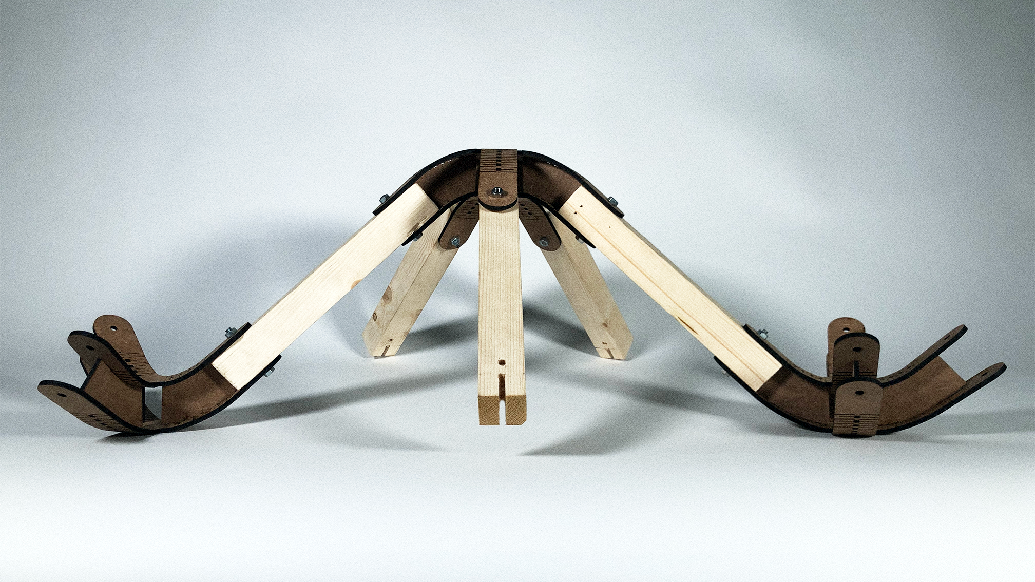
02 – KERF LASER CUTTING
Modeling: Rhino + Grasshopper
Materials: MDF 4mm, 250 x 35 x 35mm timber, screws and bolts.
Cut time: 47 minutes
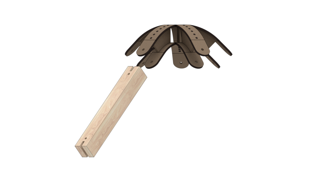
For the laser cut part of the course, a spatial joint was created, each group was assigned a different technique. This design uses a folding and curving strategy, using kerfing to achieve a spacial curved joint that incapsulates the connections to the timber beams.
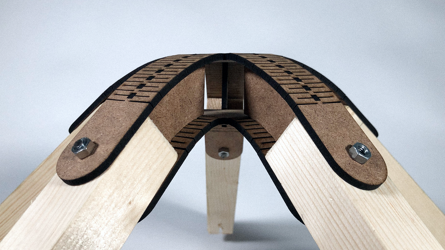
There are also guide beams made of MDF that give the appropriate curvature and firmness to the whole structure.
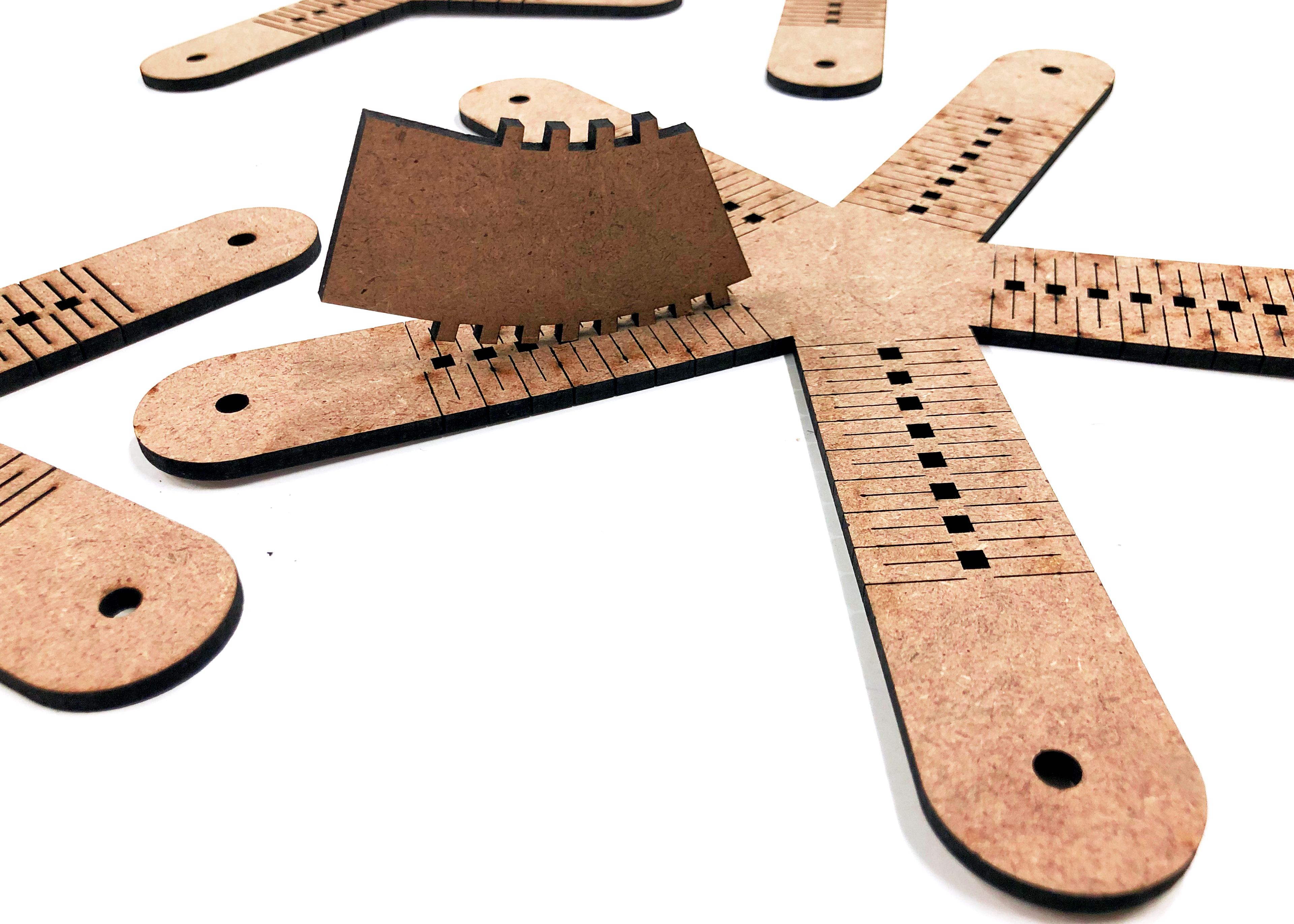
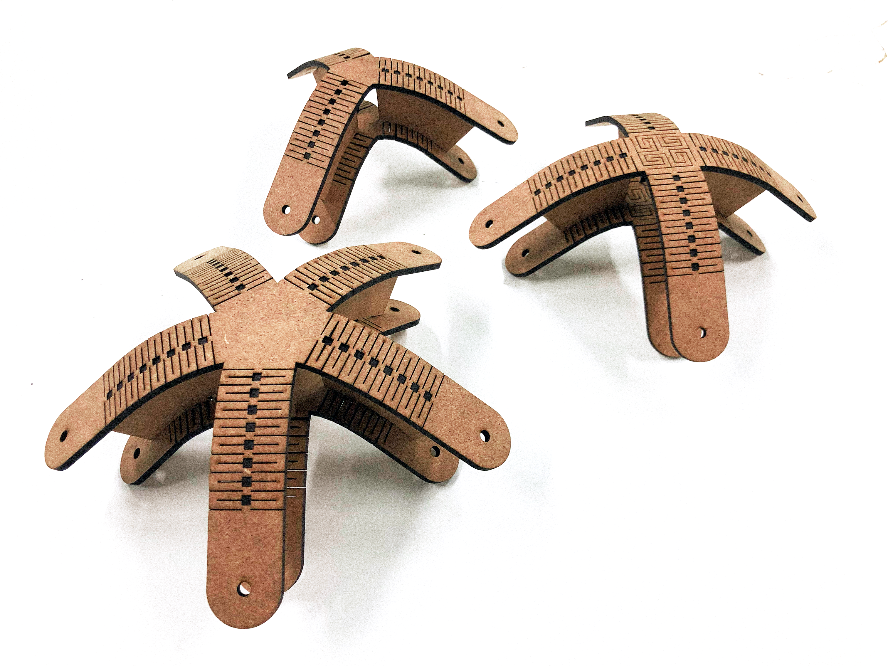
The final prototype was achieved through some testing and trial and error. MDF is not the optimal material for kerfing as it tends to break apart in points that undergo stress, usually close to the base of the curves. The solution to the issue was to double the lines in the cut plan, by doing so material mas removed instead of just cutting through, leaving more room for bending, also, three joints were tested with 3, 4 and 5 connections. The more connections, the more base area available, therefore relieving stress on the whole structure.
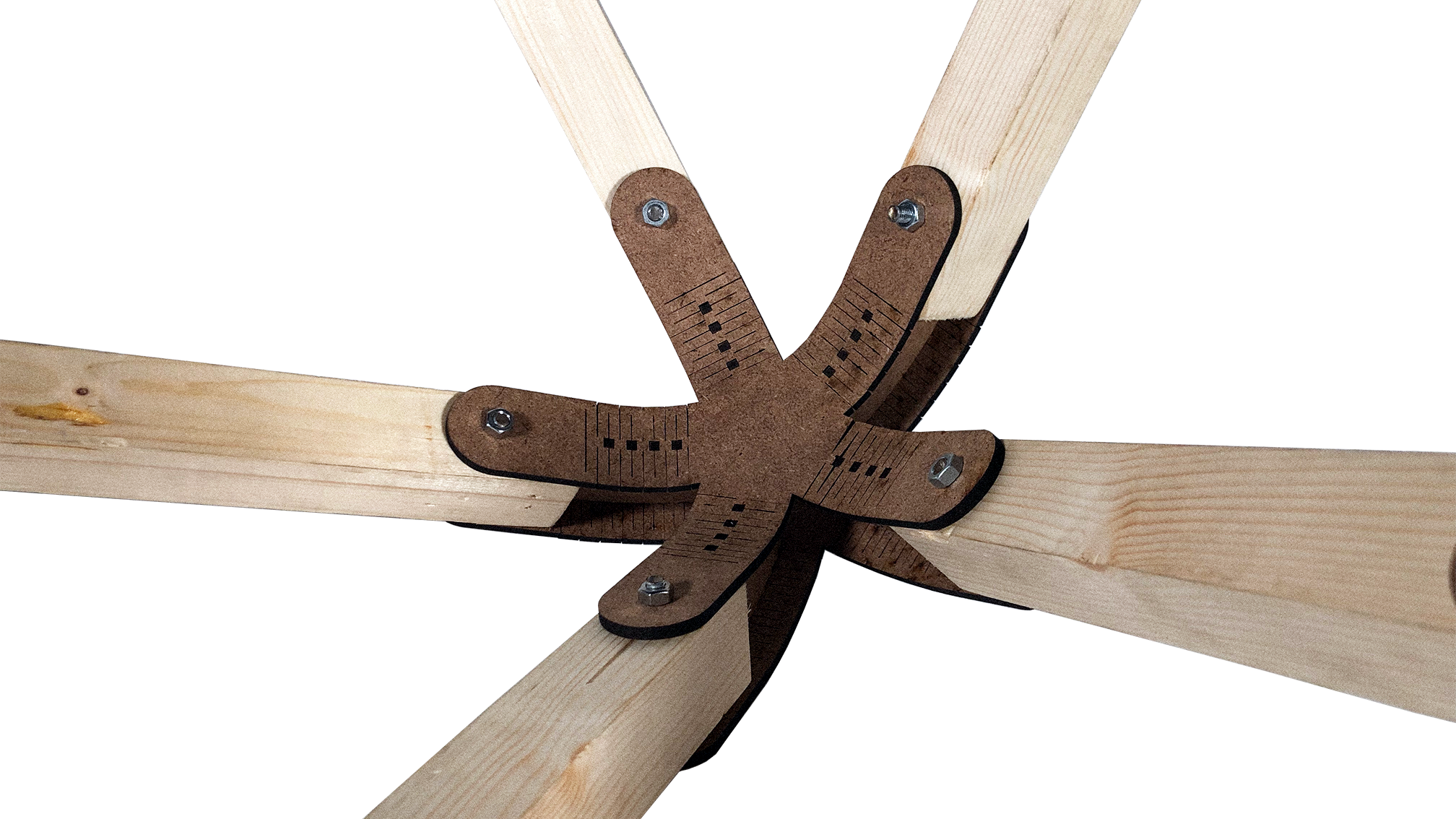
The final prototype was assembled using all three sizes of spatial joints, to test the possibilities and stress on the joints, the center piece, with five “arms” is the largest and more resistent. The beams are connected by way of a cut that fits into the curved mdf beams and bolts attached to the top and bottom of the kerfed planes.
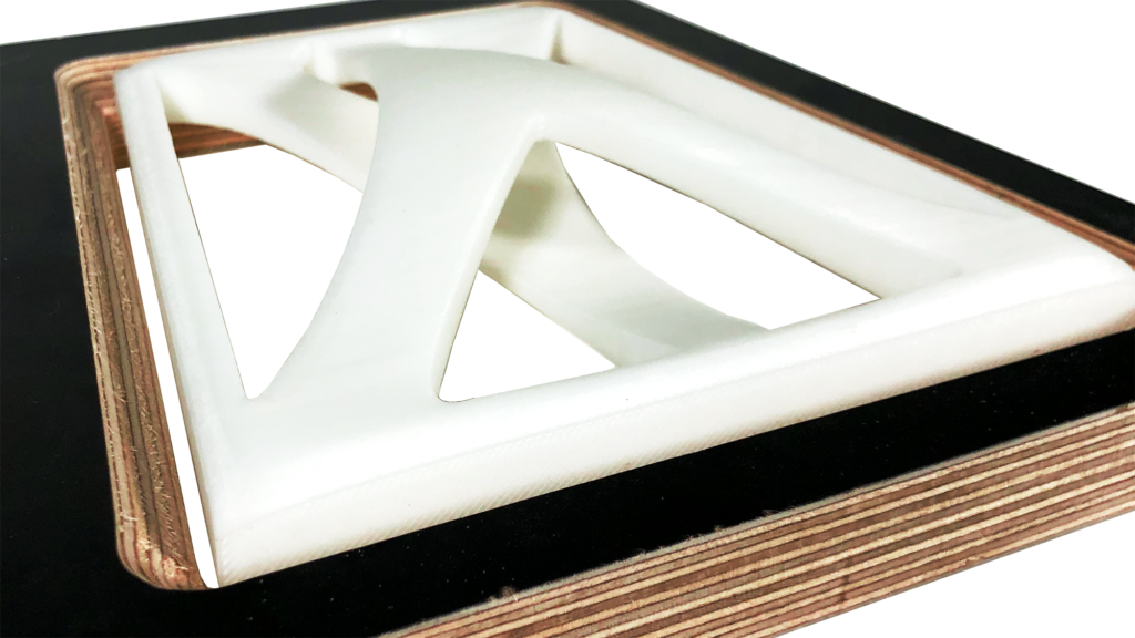
03 – TILE 3D PRINTING
Modeling: Rhino + Grasshopper
Materials: ABS plastic filament
Printer: Zortrax M200 plus
Print time: 6h 37min
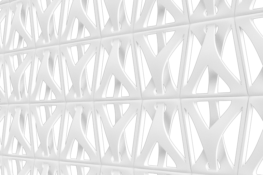
The final project for the digital fabrication course was the creation of a facade shading element using 3D printing for prototyping. This designs attempts to get as close as possbile to a 1:1 scale of a tile that could be used as such, within the 8 hour time limit for printing. It also intends to explore the possibilities and advantages that 3D printing might have over the other fabrication techniques previously learned.
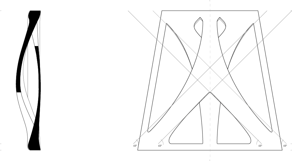
An important consideration was the presence of supports, due to the models double convex curves, the print would have to be done vertically, as such to achieve a better result and total print time supports would need to be avoided. This was done by adjusting the angles of the curvatures so they would be more than 45° in relation to the base. Any portion under that angle requires supports.
The final result is an approximation of a 1:1 tile, that could be replicated onto a facade.
03 – CONCLUSION
The Introduction to digital fabrication course was an elucidating and interesting experience. Throughout the three weeks in wich it took place new and helpful information was learned and shared. With the opportunity to test, conduct experiments, trial and error as well as learn how to model, operate the available machinery and prototype our designs and ideas.