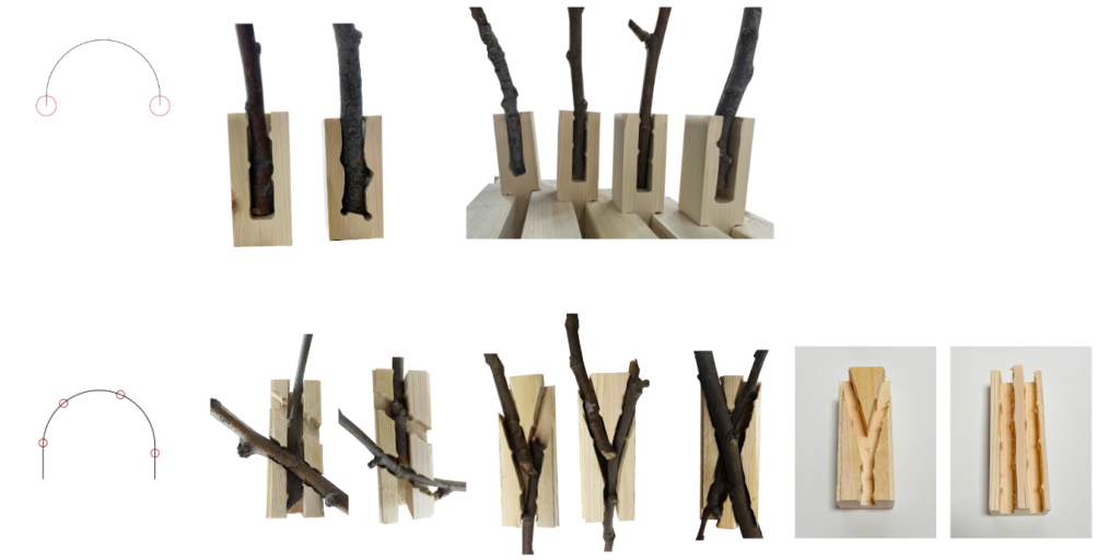
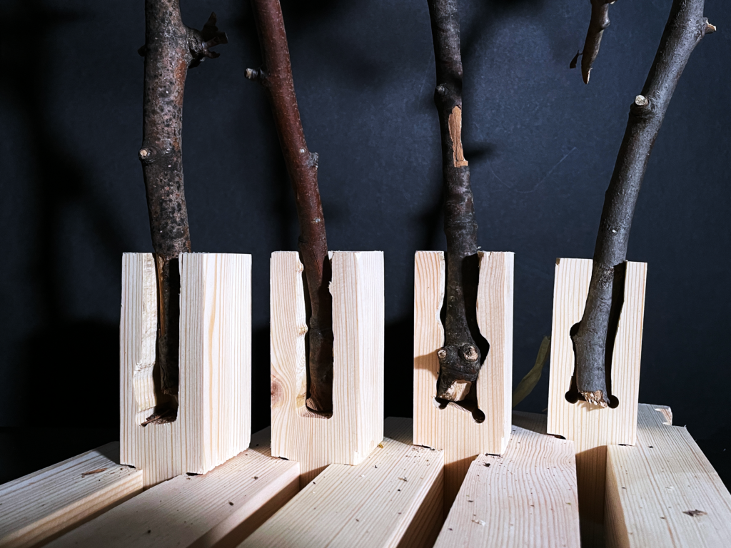
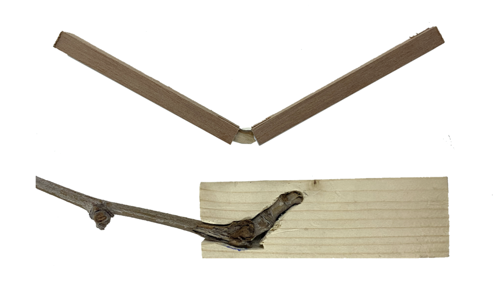
This project explores the relationship between raw wood and standard timber through active bending. A series of, 45x45x130mm, timber joint were developed in order to connect and actively bend raw wood sticks.
Relying on both standardized and customized digital construction methods, the structure considers scalability, ease of install, and natural strengths and weaknesses of the material.
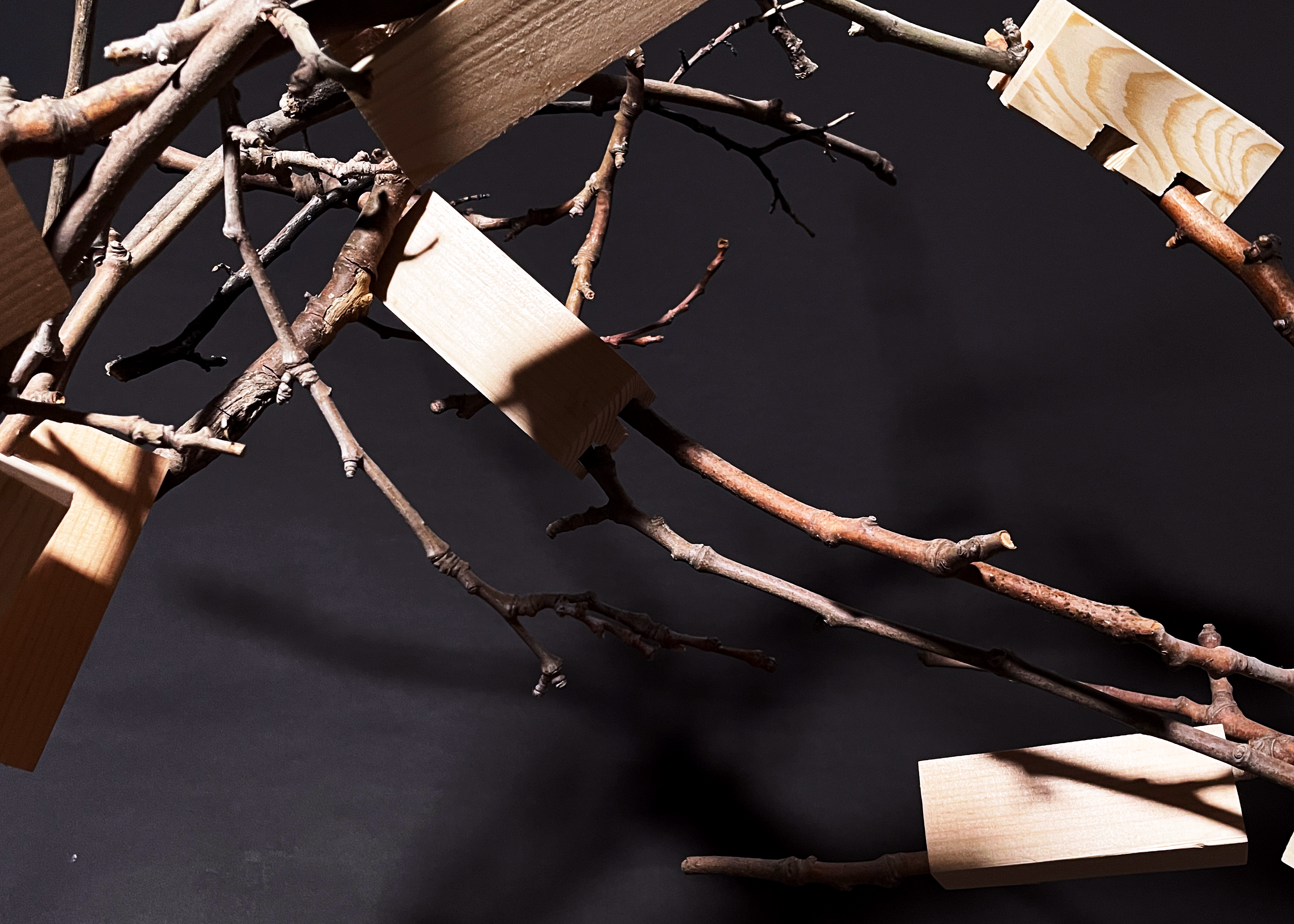
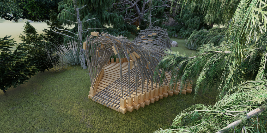
This project aims at developing a sustainable construction method that encourages and relies upon localized material sourcing; exploration and use of timber pieces as standardized guides for unique, raw wood sticks; as well as deliviring a final exposed structure that interacts with light and shadows.
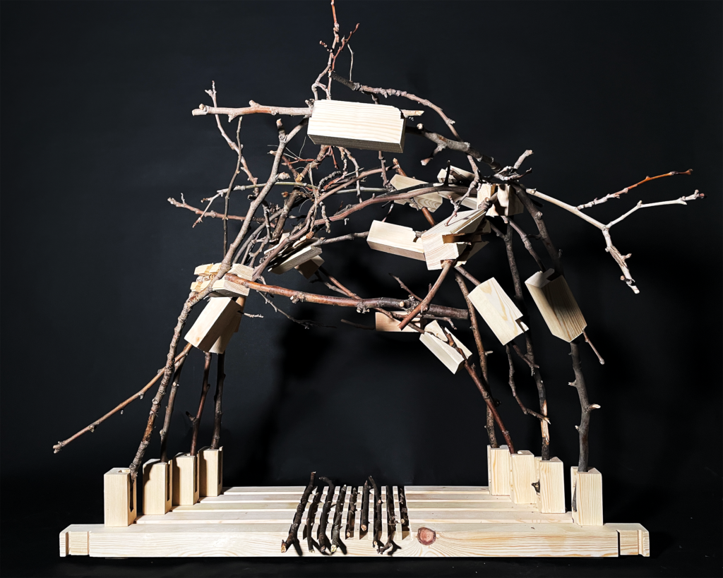
As a final product, a section of the final design was fabricated at a 1:4 scale.
Nest
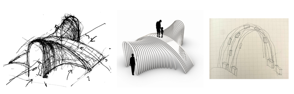
To explore the proposed concepts, a small pavillion (5x5m) was designed. This would be in essence a series of symetrical arches with a double curvature, where the user would be able to pass both through and above the pavillion. Raw wood sticks would be used to span the distances of the arches, these are connected by timber joints.
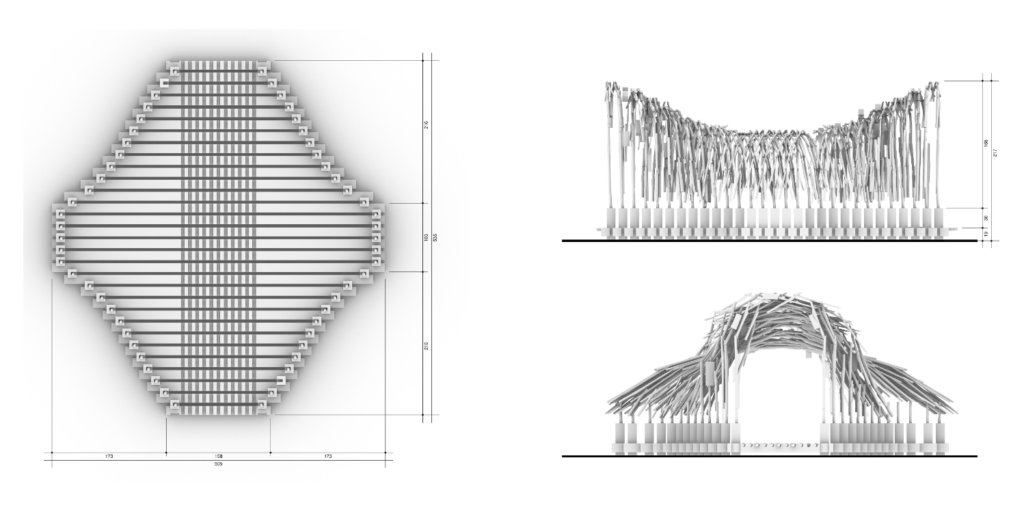
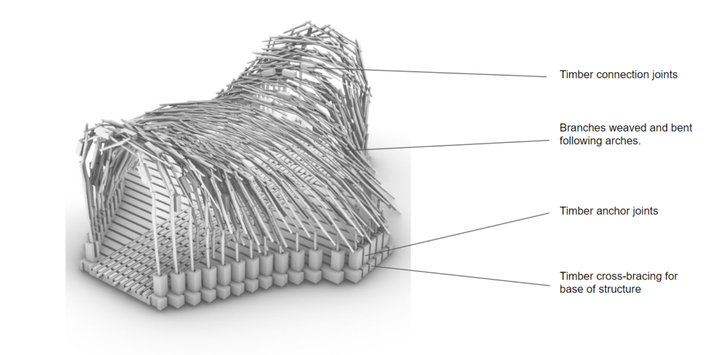
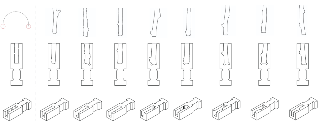
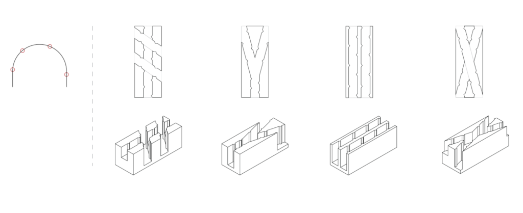
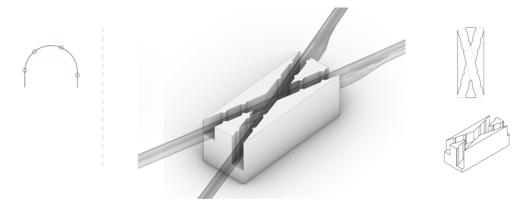
In order to anchor the sticks, which would be subject to openning forces from the bending, a joint system for the base of the structure was developed. Using a timber crossbracing and interlocking system, the bottom connectors house the larger base sticks. On all joints, two types of connectors were tested, an custom 3D scanned and standardized joints.
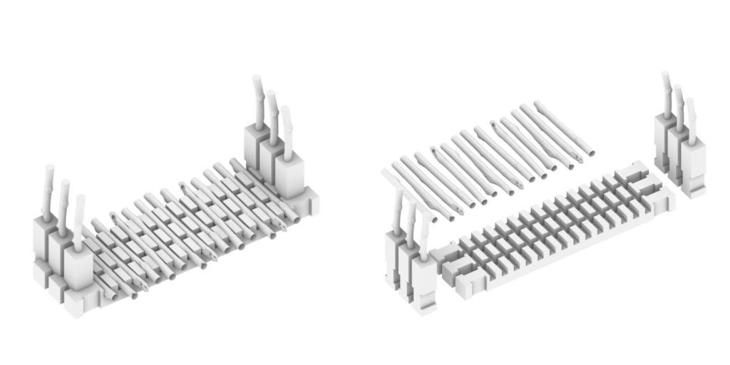
Development
The initial phase of development was an attempt to understand the behaviours of raw wood on miniature joints, using the sticks both as joints and beams.
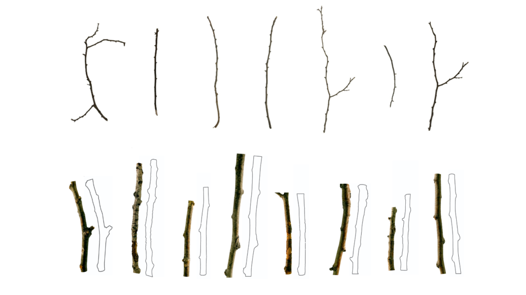
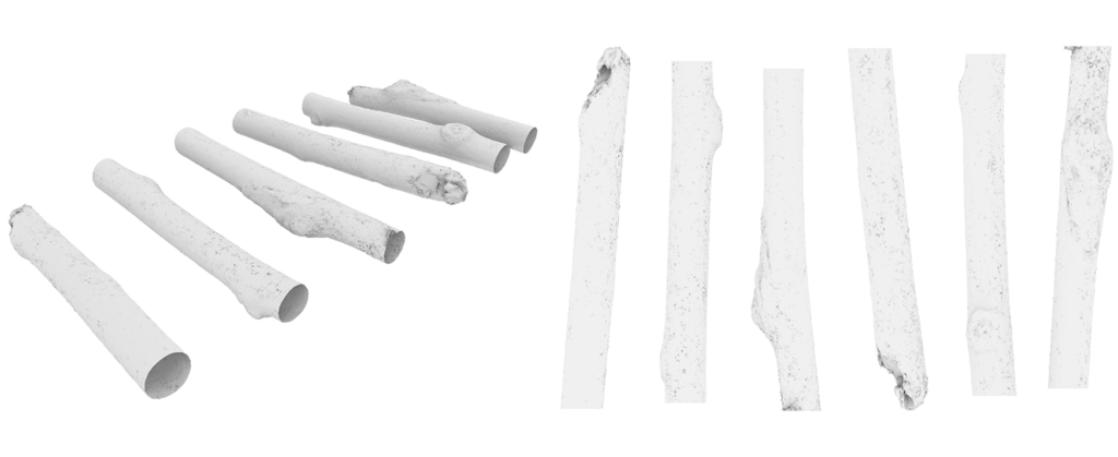
Once the tests were made and the final project defined, the path chosen to prototype the design was to use a mix of 3D scanning of the raw wood and standardized timber joints. The scanned sticks are used on the base connectors of the structure and the standard joints are applied to the arch connections, as this process is a more manual one.
The 3D scan was achieved by use of photgrammetry and the app Meshroom. Was a model was obtained, an outline of each stick was used to create a path for CNC milling into the base connectors.
A few thing where brought into consideration during fabrication of the joints, for the anchors:
- Connecting them to each other to keep tension
- Size, Thickness, Shape
- Contact to ground
- Connection between timber joint and raw wood: sanding, dowel, grooves, orientation to optimize force
As for the connector joints:
- Standardizing directionality/size
- How to lock pieces in
- Can the connector pieces double as jigs to achieve desired bending?
The final phase was the CNC milling and assembly of a 1:5 scale model of a section of the pavillion.