
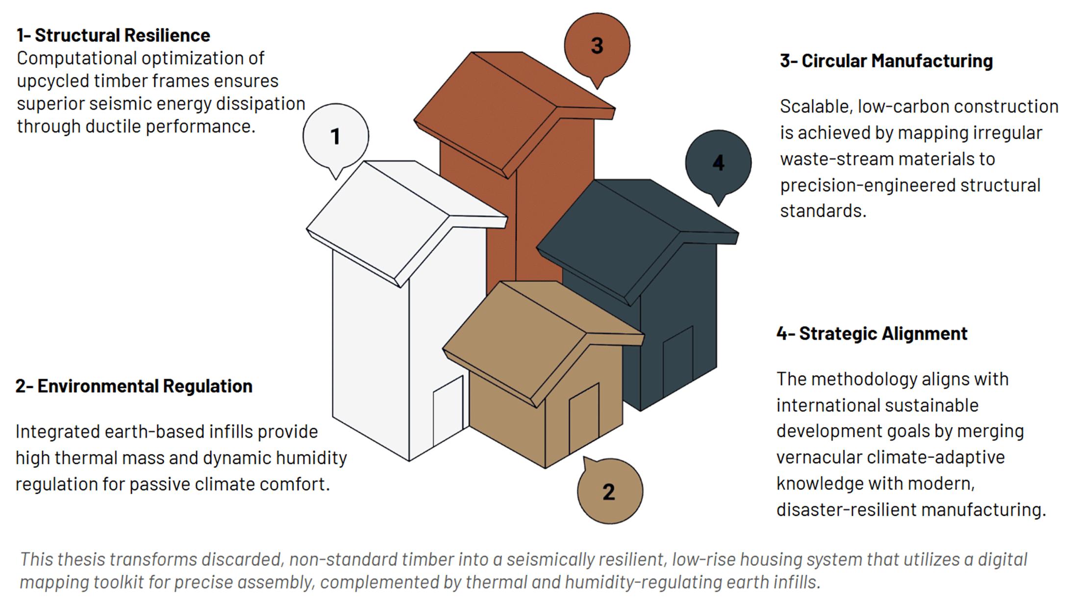
A Digital Fabrication Pipeline for Upcycling Reclaimed Timber into Low Rise Vernacular housing
The construction industry remains locked in a linear model of consumption that relies on virgin materials, often ignoring the structural potential of irregular reclaimed timber. “Non-standard circularity” challenges this rigidity by proposing a computational workflow that embraces material heterogeneity as a design opportunity. This approach analyzes raw timber scraps to generate precise geometric configurations, leading to the accurate manufacturing of building elements through the lamination of reclaimed timber. By integrating this process into a structural framework, the methodology adapts waste to meet the performance demands of low-rise vernacular housing. Ultimately, this research demonstrates that computational precision can transform material variability into a catalyst for resilient, truly circular architecture.
The Crises in modern construction
The construction industries produce a large percentage of CO2 emissions which leads towards climate crises on earth, which when further contributing CO2 emissions without awareness, leads to natural disasters. Bodies such as the European union and the United nations, with conferences as their platform to voice their concern , pointed towards a target year where all countries would achieve the construction of Zero carbon buildings. Year by year, their progress fluctuates despite billions of Euros and Dollars being invested into the project. HVAC energy consumption is also responsible for the warming of the environment just to keep the interiors of every structures cool and moderate.
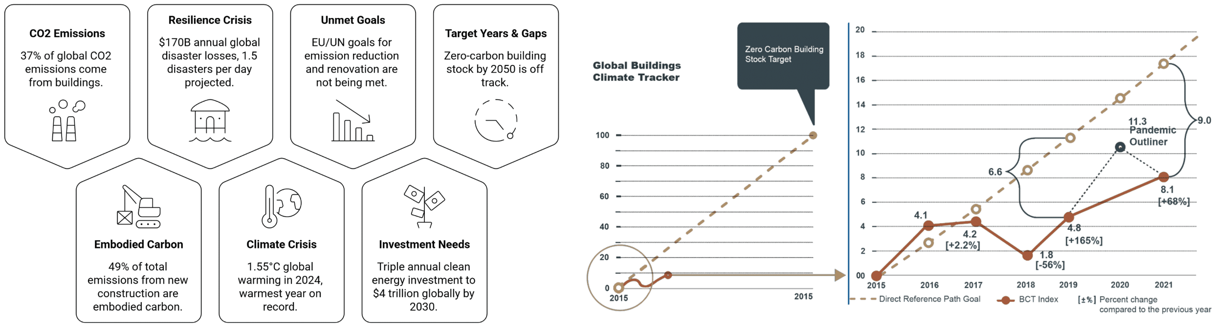
Image(left) – The EU and UN point out the major problem and take action initiating Zero carbon program. Image(Right) – Carbon tracker graph displaying a uniform target graph, with it the fluctuating EU and UN graph attempting to meet the deadline target.
The Crises in modern construction– KPK Pakistan
Pakistan is no different from other countries as it too faces the climate change, its summers growing hotter whereas its winters slowly growing warmer. Other than that, the country experiences a range of earthquakes, from minor shakes to catastrophic seismic movements leading to structures, from simple materials to midrise or high-rise structures made of the state of the art construction materials like brick, concrete, cement, RCC etc, to their structural limits and worse, break and fall, demolished by a natural force.
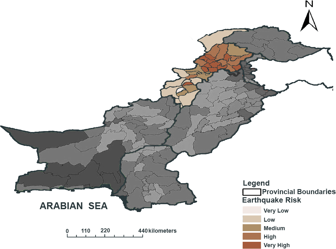
Image – Map of Pakistan showing seismic zone intensities in KPK.
KPK has a climate of really hot and humid summers and warm , humid winters. During the Summers, the energy consumption for cooling gets higher and more expensive per year , the same could be said for winters where the nights are cold and heating to keep warm is needed. While structures in small towns consist of local stone masonry, hollow concrete bricks , wood and whichever locally available materials, larger cities construction use the standard construction materials like brick, concrete , RCC etc, unconsciously paying the price of heating its own environment , not expecting what’s coming.
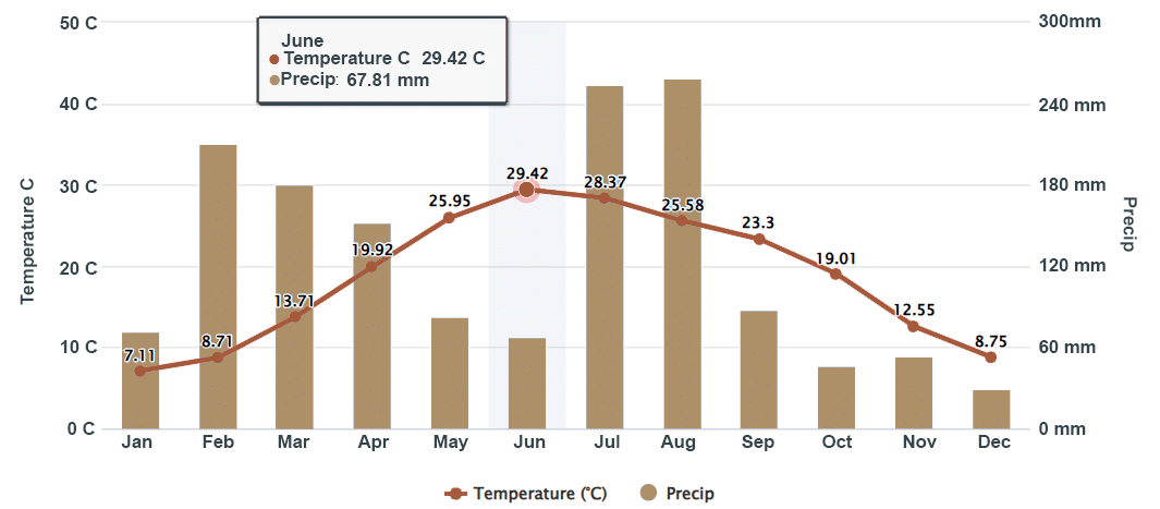
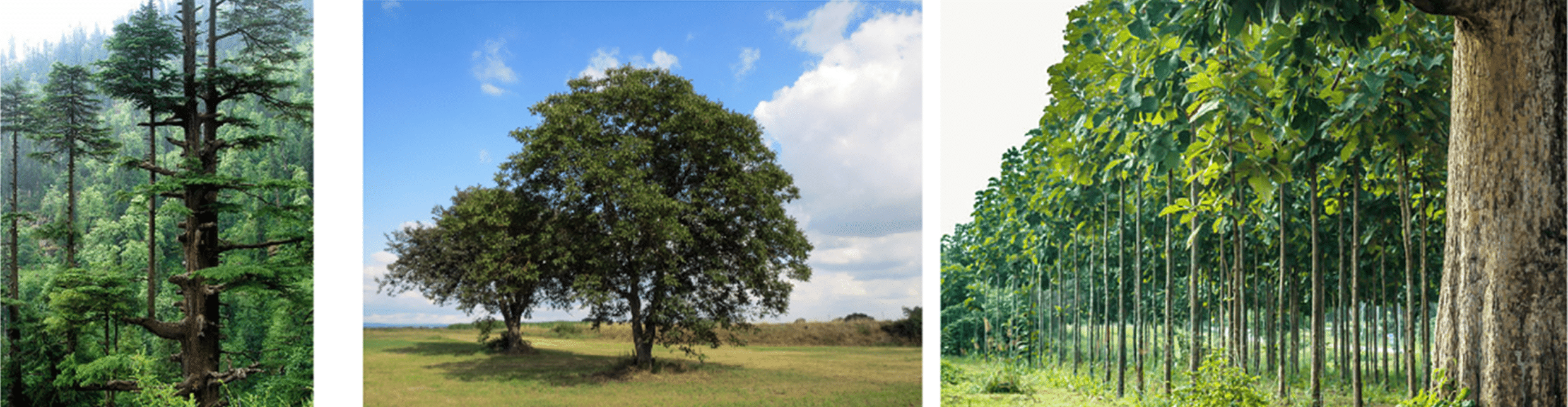
Image above – Climate graph of KPK
Image from left to right – Cedrus Deodora, Wall-nut tree and Teak tree, used for construction of buildings and furniture.
Vernacular Reframed-Preindustrial Revolution Structure-Dhajji Dewari
Pakistan houses a lot of Vernacular architecture not only reflecting regional culture but its structural intelligence as well as environmental regulation of heat and humidity, adapting in changing climate. One of these structures will be the case study of this thesis for displaying structural intelligence used against seismic activity, lasting longer to stand and accommodate people. served as a role model for construction systems after the earthquake of 2005, commissioned by the Government of Pakistan to build houses using this structural system. Aid groups would give workshops in craftsmanship of the building elements and joinery of laser accuracy in order for the joinery to fit without any issues. In tree years or more , 120,000 rural houses were built using this structural system. However, this structural system slowly faded into the earth as construction manufacturing industries promise safety for using carbon emitting structural elements ( brick, cement concrete etc).

Image- Example structure of Dhajji Dewari in Pakistan
Preindustrial Revolution Structure- Dhajji Dewari Structural Systems
The Dhajji Dewari has a parameter thought by the past masons ; the denser the X brace wall chassis , the more resistance it would show against seismic activity. The X pattern gets smaller yet denser to structurally resist more against the seismic activity, retaining its structural form after the activity.
If we look at it as one wall panel as an example, the outer parameter consists of base and ceiling beams of 10×12.5cm cross section , and primary posts/ Load bearing posts 10×10 cm thick in cross section. The inner parameter , consists of thinner posts of 5x10cm called secondary posts . The primary and secondary posts are held together using horizontal elements/Horizontal plates , nailed to the posts to hold them together . Pakistan’s Dhajii dewari systems , updated by an engineering university in KPK, modernized this system by using nails as connections instead of cutting notches to connect the plates to the post. The pattern with the space grid formed by the posts and horizontal plates, an x pattern is fitted in and nailed to the posts .
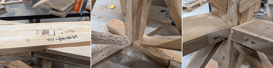
The joineries consist of overlapping joints for connecting base segments, and if the structural base requires of extension , scarf joints were used. The connections between the base ,ceiling and posts are of tenon and mortise joinery , which has higher structural strength connectivity. The connections between posts base and ceiling, forming a outer parameter cage, are reinforced using nails , wood blocks or iron straps to further reinforce the posts structural stability, connectivity and resistance, ensuring they do not fall or slip. The horizontal plates and X brace are connected using nails . Nails were preferred than making more notches , saving time in manufacturing , retaining the building element’s strength.
Image- Overlapping joinery for base, post connected to the base elements using nails and blocks for firm hold/connection between post and beams. Nails were used to connect the horizontal plates and X brace to the posts.
Preindustrial Revolution Structure- Dhajji Dewari Structural Limitations
Despite its structural intelligence , there are limitations in maintaining the resistivity. The volumetric design cannot go more than the first floor ( Ground floor then floor above) in intense seismic area, and the length cannot extend more than 3 times its width dimensions. The interior spaces should be designed within the rectangle parameter , with no volumetric extrusions .
The same could be said about the openings , the minimum the openings the better, which could lead to ventilation in some interior spaces. Veranda designs are also limited to the center than the sides.
Preindustrial Revolution Structure- Dhajji Dewari Seismic tests
An engineering university in Peshawar KPK ran tests on the seismic resistance of the Dhajji Dewari wall. Researchers prototyped walls , each wall having certain parameters to test resistivity. Most of them range from the density of the chassis, the amount of nails used , the amount of applied force it can withstand etc. Why nails were mostly preferred than making notches to connect the structural elements together? Nails rub with the wood during seismic motion, forming friction which dissipates the seismic load, reducing the load to its minimum when reaching the foundation, allowing the structure to remain as it is.
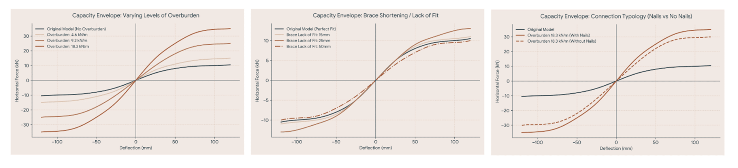
Graphs here show even with higher application of force, the structure resists showing below 1 cm deflection. With more screws used against the application of max. force, it shows more resistance.
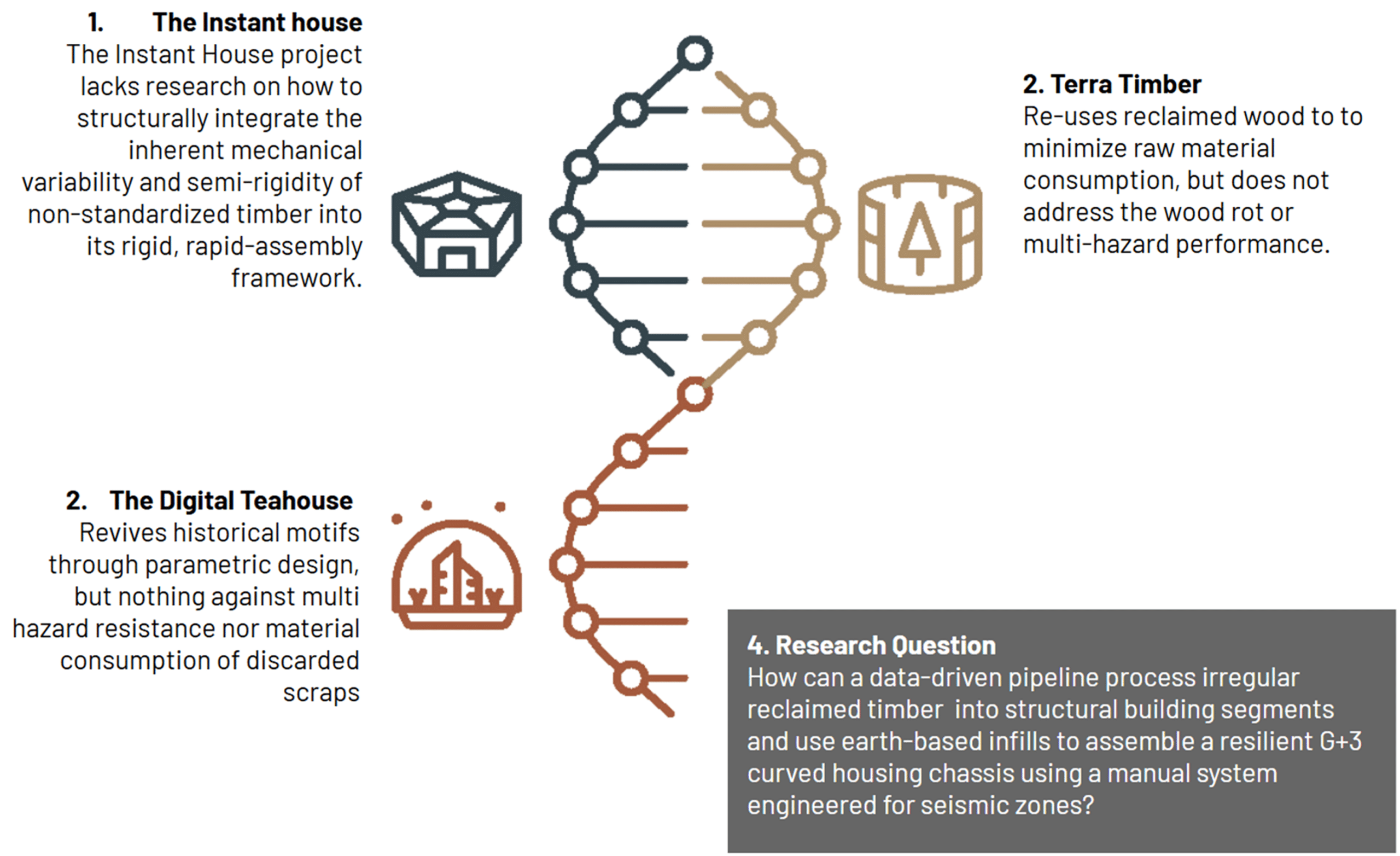
The Research Gap– Global Case studies – The Digital Tea House
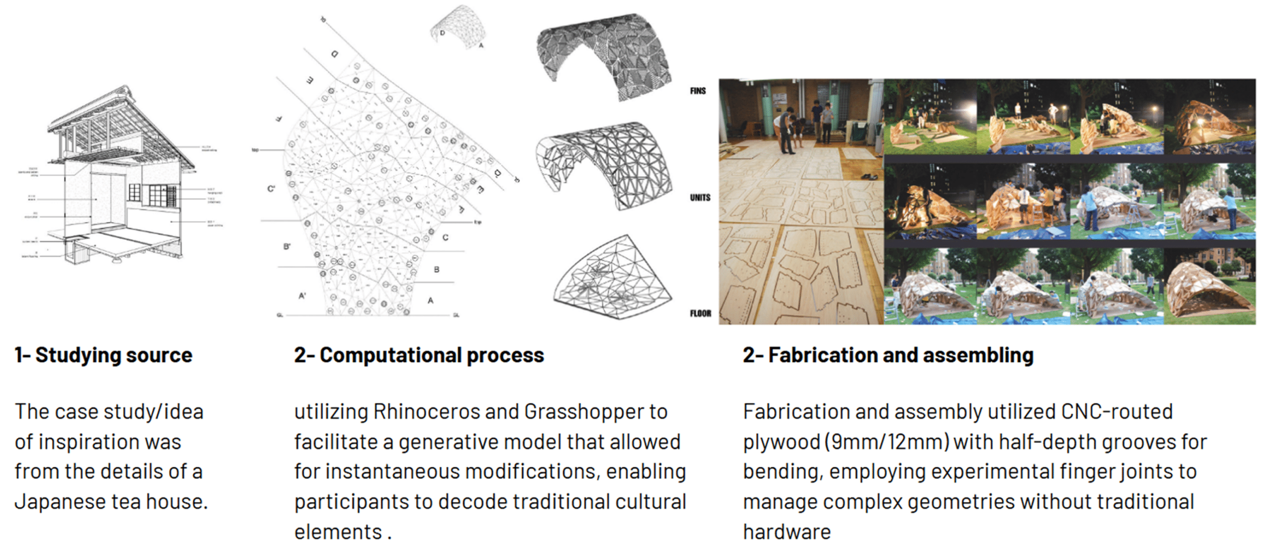
This project aimed to revive an old culture , giving it a modern physical look of a pavilion using computational design. The architects studied details of an ordinary Japanese tea house , from its volumetric details to lighting, texture details etc , applying its logic in computational design to generate forms , texture as well as complex joinery achieved using CNC technology.
The Research Gap– Global Case studies – The Instant House
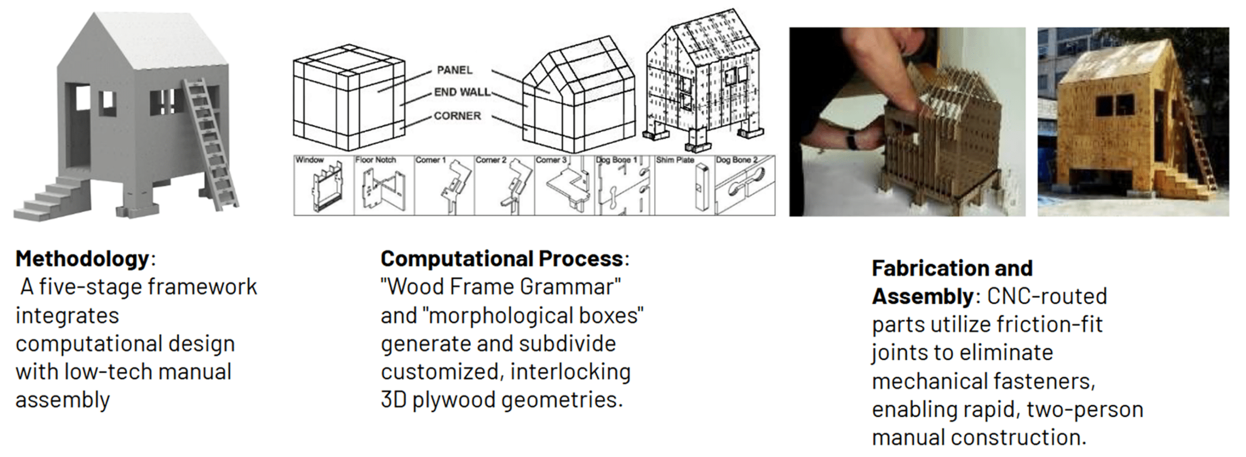
The Instant house used computational design to find and generate light geometric designs that can easily be prototyped and manufactured using CNC cut plywood to then be deployed to the affected areas.
The Research Gap– Global Case studies – Terra Timber
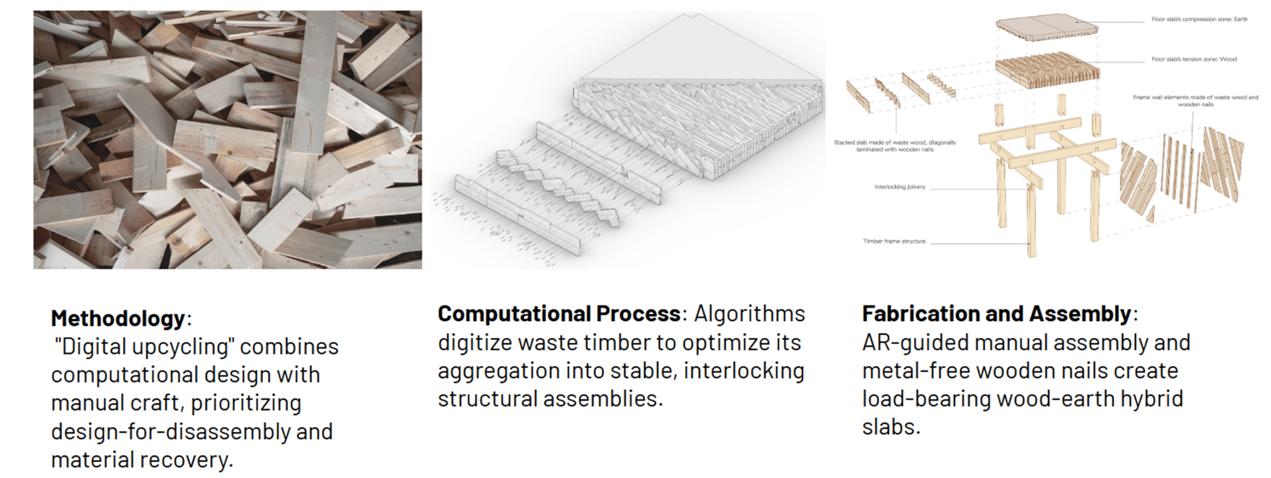
Terra Timber is a project displayed the methodology of using reclaimed timber wood and upcycling them to form a sturdy structure using computational design for the placement of wood , fabricating building elements which can be repeatedly manufactured to form a whole building structure itself. The joinery were done digitally before fabrication.
Research Question Synthesis
Thesis Statement – Aligned Targets
Methodology Development
The methodology became a template , a roadmap towards building up the thesis using the statement that answers the question. Phase 1 stresses on decoding the dhajji dewari structural mechanisms/joinery etc. It also focuses on the collection and recording of reclaimed timber as well as its physical properties , its physical warping , knots etc. Dhajji dewari originally uses stones as infill with clay being an adhesive connecting the wooden brace and the stone infill. However, the stone infills despite being weights to stabilize the wall , it does not have strong insulation properties , even though the clay plays in absorbing humidity to prevent wood rotting. Earth infills were proposed to act as weight substitutes as well as having higher properties of heat and humidity regulation.
Phase 2 focuses on computation workflow, looking into the reclaimed timber data and laminating, later assigning the laminated timber to the specific building element before fabrication, which can be then structurally tested to see its structural resilience. Phase 2 not only focuses on the analysis of the wooden structure but also test 3 sets of infill mixtures; Earth, Earth + lime powder and Earth + lime powder+ straw. They would be tested in terms of strength as well as heat and humidity regulation using an Arduino powered hygrothermal box. However, despite this phase not just focuses on the digital lamination and assignment, this phase also focuses on increasing the resistance/durability of the structure by changing the exterior wall, from flat to another geometric shape like a catenary curve for these following reasons ;
Inherent Buttressing: The continuous alternating curves function like a self-supporting arch system, distributing physical loads smoothly across the structure rather than letting stress concentrate at single failure points
Bending Stiffness: Flattened walls easily fold or topple when pushed from the side (lateral force). A crinkle-cut geometry increases the wall’s effective structural depth, rendering it multiple times stiffer against horizontal shaking
Flexibility Over Rigidity: Rigid, unreinforced straight blocks break under sudden movements. Sinusoidal configurations allow minor joints to micro-flex and absorb movement without threatening the integrity of the wall
Phase 3 comes after computation, which is fabrication. After computationally laminating the reclaimed timber, assigning them to the structural element and digitally modelling the joinery, they undergo fabrication where the laminated wood transforms to structural elements such as posts with tenons on its edges, beams in segments having overlapping joinery and etc.
The collection and recording of scraps
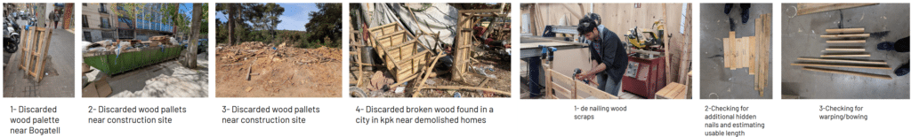
Images ( left from 1-4) – reclaimed palettes near Bogatel stop , Valdaura and places in Peshawar city,Pakistan. Images ( right from 1-3) – De nailing palettes and recording their measurements and physical properties.
Understanding tools
In the past, Dhajji dewari was constructed by hand, as in building elements were hand crafted to pin point precision. The only problem was, the manufacturing process was slow, also taking alot of human energy and fatigue. This was tested , comparing with the power tools such as CNC machine . The results are that the cnc machine produced more clean cuts as it can perform multiple programs to cut wood, from straight angled to forming curvy surfaces,

Computational Framework-Pseudocode
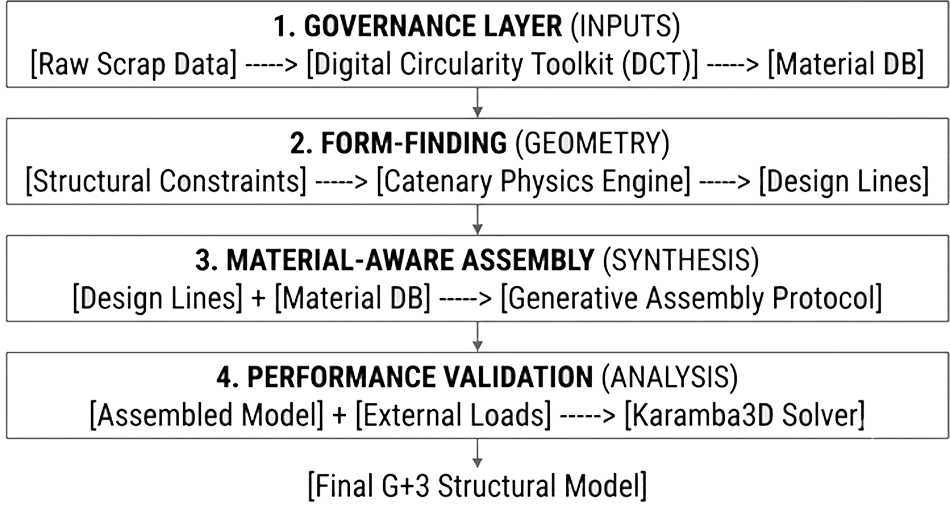
The computational workflow consists of several phases brought in order as a road map leading from the design lines and digital timber to working together as a structure. The timber data recorded in excel sheet is converted to digital models , extracting data such as its cross sections, lengths , center points and hulls ( planar surfaces that are the lengths and heights of the digital models), and since it would be difficult to assign the whole laminated scraps to to the whole building structure, a portion of the building , a wall would be selected to perform this process. Design lines are generated using grasshopper , its physics using kangaroo plugin. After this, the timber pieces are laminated using the raw data from both the design lines and from the wood digital models , are input in python with a code to process the lamination and assignment of timber to the design lines. Those structural elements are then tested using karamba plugin to structurally test the design element , from static load to lateral loads etc.
Performance Validation
Firstly, lab controlled testing needed to be done to see the limitations of Dhajji dewari. The structure of 6×6 meter base parameter with no interior walls. The interior walls act as a secondary resistance against the seismic activity. Hence, exterior walls were tested as it primarily takes on the seismic load .
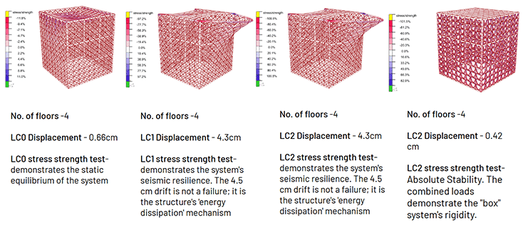
The flat wall lab controlled structure from analysis , load case 0 (gravity) and load case 4 ( infill weights ) show least displacement below 1 cm , whereas wind and seismic load show displacement above 1 cm. However , those two loads when subtracted using LC0 and 4, the displacement is actually 3.22 cm.
Structural Proposition – Crinkle cut exterior wall
After the flat wall analysis , crinkle cut walls were proposed to be the exterior wall design to resist seismic activity better. The reasons for such are because :
1- Inherent Buttressing: The continuous alternating curves function like a self-supporting arch system, distributing physical loads smoothly across the structure rather than letting stress concentrate at single failure points
2- Bending Stiffness: Flattened walls easily fold or topple when pushed from the side (lateral force). A crinkle-cut geometry increases the wall’s effective structural depth, rendering it multiple times stiffer against horizontal shaking
3- Flexibility Over Rigidity: Rigid, unreinforced straight blocks break under sudden movements. Sinusoidal configurations allow minor joints to micro-flex and absorb movement without threatening the integrity of the wall
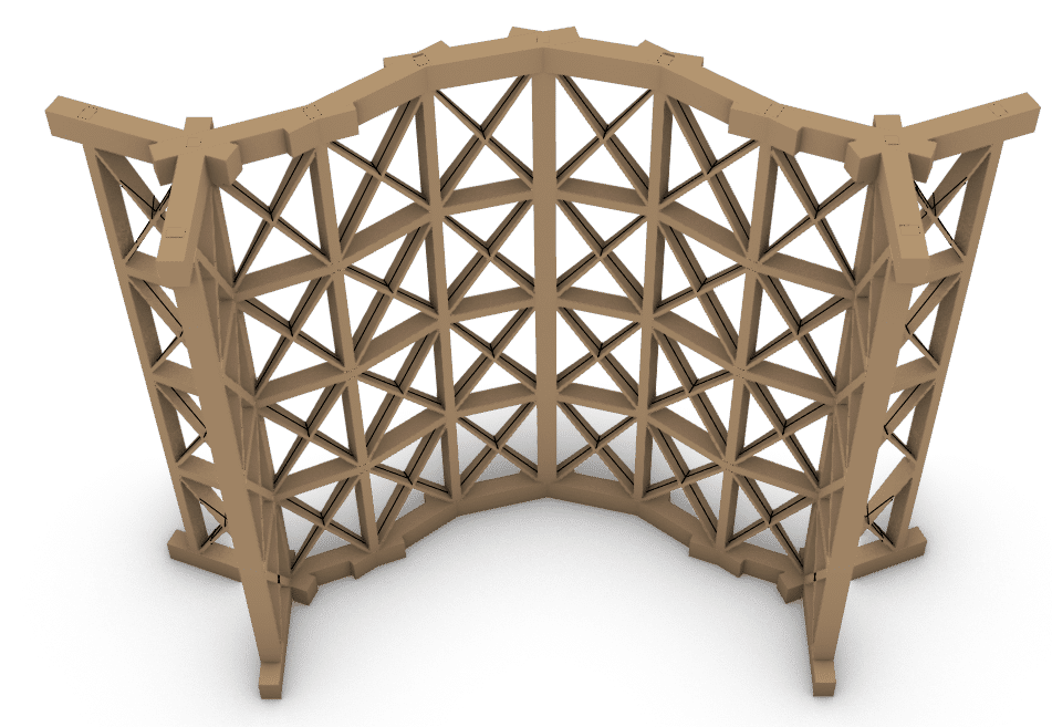
So, computational software like rhino3d and grasshopper can aid in forming these curved walls using kangaroo physics. However, the catenary curve’s curvature depends on the density of the x brace chassis, if its 3 secondary posts , its curvature would be smoother, if it were of one secondary curve, it would not be smoother, rather edgier . In this project , the 2 secondary posts were selected as test.
The Assembly Logic – Lamination and joinery

The animation above shows how the wall would be assembled , starting with the base in segments being fitted together using overlap joinery. The base segments were modelled to not only connect using overlap but interlock to increase resistance. After the base was formed , the posts would connect with the beams using their tenons , same for the ceiling beams . Notches were also modelled on the posts to connect with the horizontal plates just as a test, but due to the university of Peshawar’s data on the seismic test, nails were preferred to dissipate the seismic load. The horizontal plates were nailed to the posts to not only hold them together but to also form a grid to contain the x brace , forming a chassis. This was tested using 3D printed segments.
The Lamination Process
After the computational workflow, the reclaimed timber are laminated in certain steps.
1- Remove the unnecessary lengths from the reclaimed timber which could then be used later if needed.
2- Instead of using a planar machine, sand the surfaces of the timber where it will be laminated, forming a smooth surface.
3- Group the timber pieces according to the computational lamination
4- As each lamination is different in number, in general, stack the first two pieces of timber on top of each other , drill in zigzag pattern 10 cm apart from each other , drill till the end depth.
5- Clean the drilled holes using an air-pressure gun, and apply glue in the holes and on the surface.
6- Hammer dowels in the first layer timber , then hammer the second layer timber on top of the first layer which has dowels.
7- Repeat the process for lamination
8- Clamp the laminated pieces tightly and wait for 24 hours for the glue to perform as an adhesive merging the pieces together.
CNC Simulations
Rhinocam was used to test simulations on CNC cutting , subtracting the wood from the laminated timber. For beams they were mostly pocketing for half-lap joinery and tenon and mortise joinery. The same thing could be said for posts, horizontal plates and Diagonals forming the X brace pattern. But, theoretically, CNC would take a lot of time in cutting the shapes despite accuracy and tolerance. So, the strategy was to divide the work and get the structural elements made simultaneously. Elements such as posts, horizontal plates and diagonals for X brace can be engraved according to the digital model of the prototype, and can be manually cut using power tools such as power saw etc.
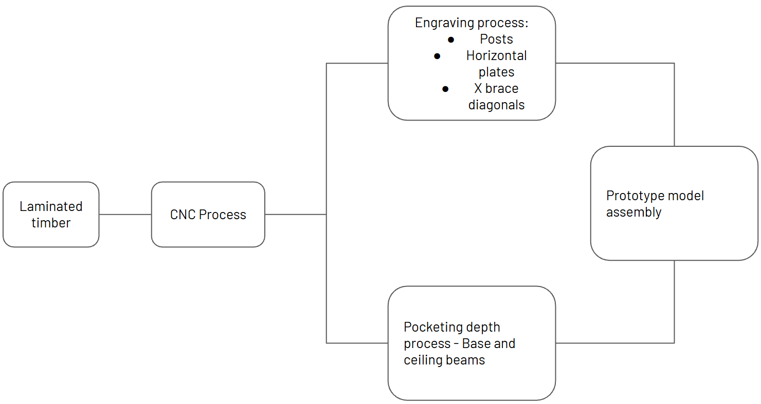
This strategy was proposed to speedily mass produce the base and vertical +horizontal elements simultaneously.
Assembling the prototype
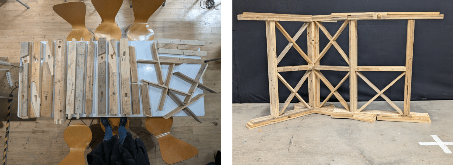
The structural elements after fabricated to then be assembled into a prototype , a one meter high wall showing the joineries as well as the angled connectivity of a section of a catenary curve wall. The grid without the x brace pattern shows a window opening.
Earth based infills
Dhajji dewari originally used stone infills as weights to stabilize the wall as it was a locally sourced material. But there is an issue, stones heat up during the summers and gets cold during the winters, the expanding and contracting of stone could cause it to crack and break, which could potentially fall down from the structure. Earth based infills were proposed to replace the stone infills as they not only can act as weights to stabilize the wall , but also has heat and humidity regulation properties, meaning it can regulate structure’s interior environment and reduce the HVAC energy costs. Earth is a natural sensor of heat and humidity , whenever it senses a reduction of heat and humidity below 40%, it would release the stored heat and humidity to moderate the environment . Below 40% would cause human’s skin to crack and irritation, whereas above 60% would cause excessive sweating and tiredness.
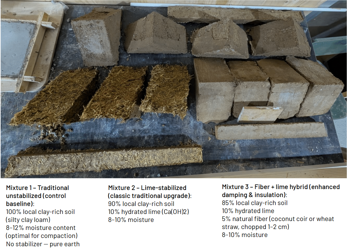
Three mixtures were selected to be tested for their strength and regulation of heat and humidity.
1- Plain earth infill
2- Earth +Lime powder
3- Earth + lime powder + Straw.
Strength Tests
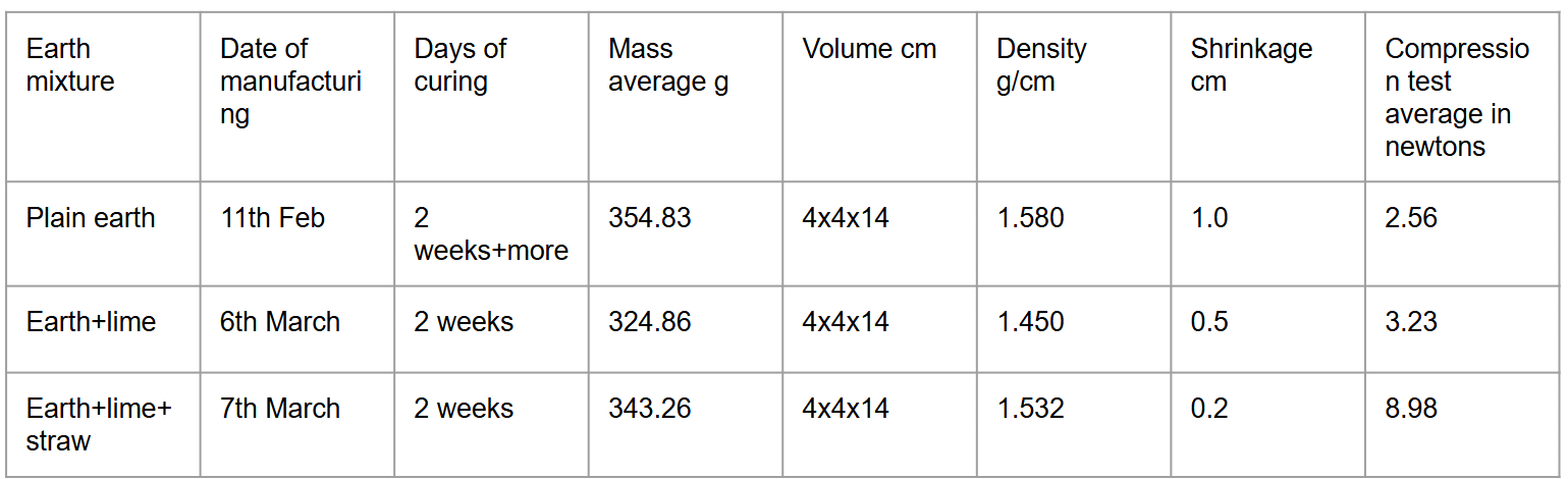
The third infill mixture surpasses the other two infills as its shrinkage value is a lot less, meaning when fitted in the wood chassis it would fit perfectly without an issue of getting loose and falling. It can take alot more compression than the other two models , property reason is because the straw acts as fibers holding the material together during the wear and tear process.
The Hygrothermal Machine
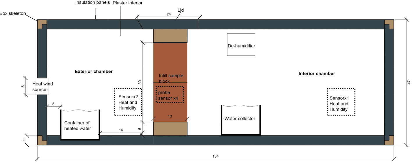
The Hygrothermal machine was used specifically to test the infills heat and humidity regulation properties of the infills. The box is divided into two chambers , the exterior chamber simulates the environment of KPK region while the interior chamber acts as the interior of the structure, showing data of the resulting environment . Both chambers are divided with the infills in the center , having the standard thickness of 10 cm . Both chambers have sensors attached to record heat and humidity data . The chamber is insulated using foam boards, with a layer of plaster to seal off the smallest openings to prevent errors in data reading. The infills had probe sensors detecting heat and humidity being stored in.
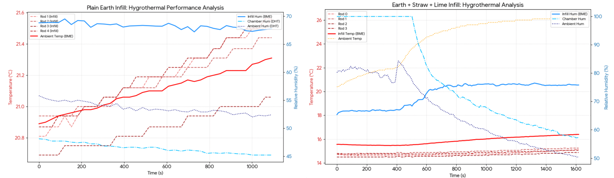
The plain earth infills produced the worst results as heat started to increase in the interior chamber . The probe sensors showed an increase heat and humidity storage as well as quick release of heat and humidity into the interior environment . The third infill performed more than exceptionally well as it stores heat and humidity more in capacity constantly due to straw forming additional capillaries to store more. The graph also shows there was a drop in temperature and humidity, moderating the interior chamber’s environment . The infill senses the environment and absorbs , later emitting when needed.
Conclusion
This research demonstrates that the future of resilient, sustainable architecture does not lie in the invention of new materials, but in the computational evolution of vernacular wisdom. By digitizing the Dhajji Dewari system and optimizing reclaimed timber through generative design, this thesis proves that high-performance, G+3 scale timber structures can be achieved with zero-waste, material-efficient, and structurally optimized methodologies. We are not just building; we are curating a circular, structural legacy. Thank you.
