
The research aims to take an advantage of the knowledge from the past and integrate with today’s technology to construct novel and complex forms. The intention is to integrate fibers during the 3d printing process to support the cantilevers in wet state as well as find the optimized method to lay the fibers. This method may include the anchor points at various levels around the structure and digital tools to locate the optimized fiber locations and orientations.
The research focuses on the design and fabrication aspect of the optimized placement of fibers, to support the earth 3d printed cantilevers through digital analysis of the geometry, to identify the orientation of the fiber placement and evaluating the most feasible method to add fibers in the wet state during 3d printing.
Additives and fibers have been a significant part of the Earthen mixes, as they provide the necessary strength, binding properties, weather resistance as well as aesthetics to the structure.
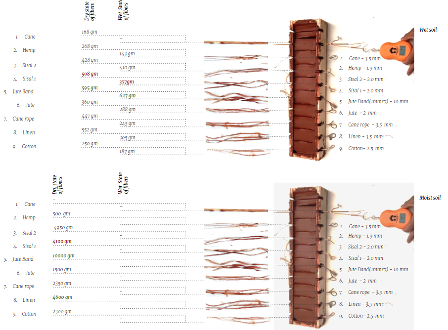
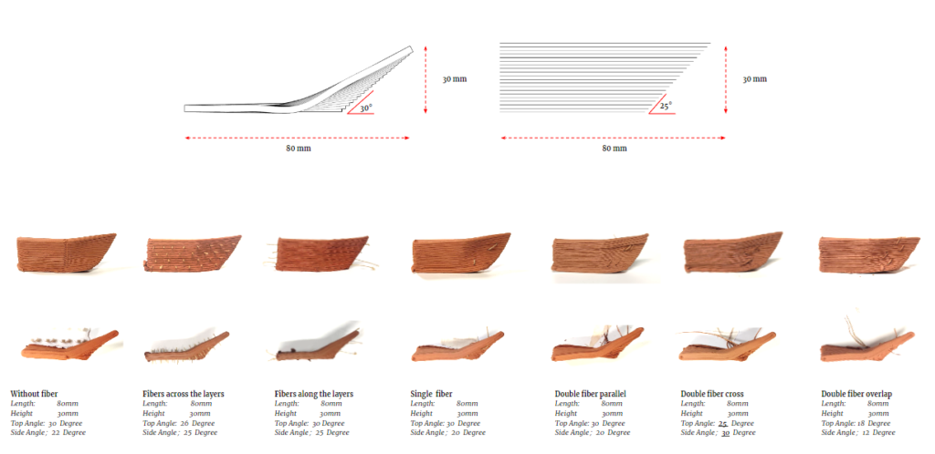
Tested in the wet and dry state of fibers and soil
Addition of fibers from macro to micro level observed to be bestowing necessary strength to not only the structures but also the finishes. It is observed that the addition of fibers in the earth reduces the shrinkage during the drying process and also provides required friction and resists the displacement of the structure.
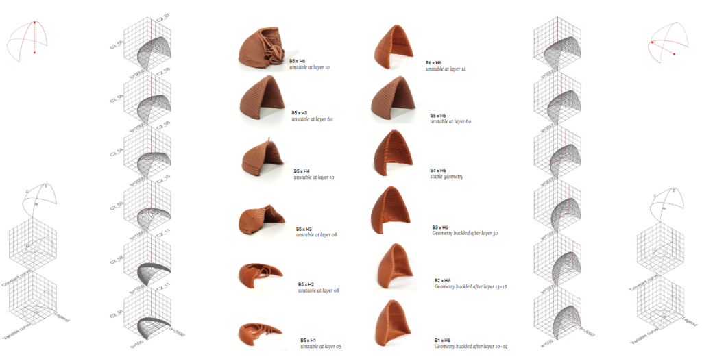
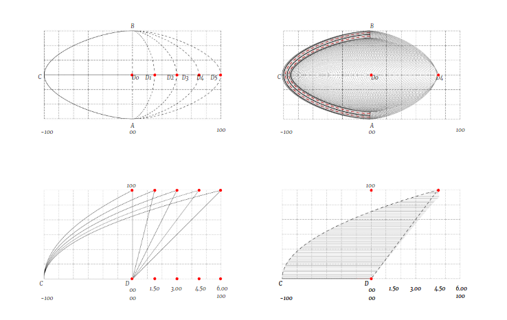
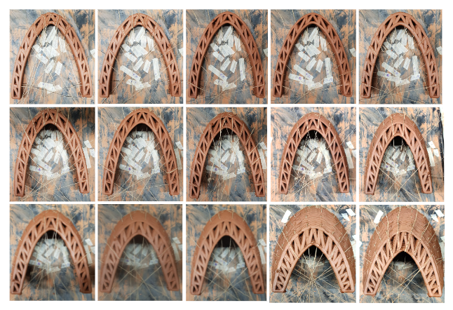
To enclose a space, we considered certain curves together which form a semi open space. The 1st catalog was iterated with varying base curves and keeping the top curve constant. Evaluated with the maximum volume criteria as well as the printability of the geometry.
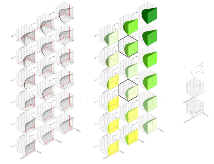
Selected Iterations: Geometries with higher Volume and stability
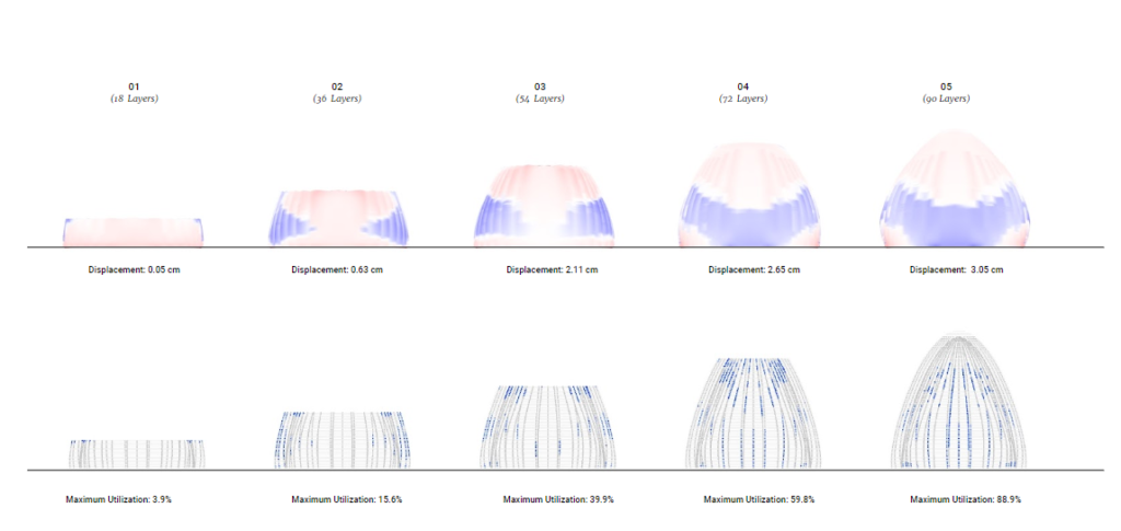
The chosen geometries were printed to observe the behavior for their stability and the further modifications were made to improve the printability and adapt to the scaling up.
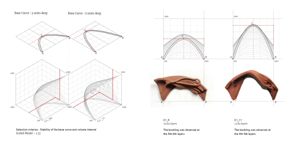
Layer height – 1.8 mm
The Geometry was modified to improve the stability and printability.
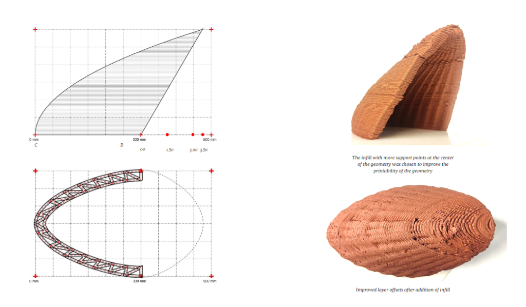
The real scale model was scaled down and added with the thickness of a double layer for stability. And infill was introduced to improve the slicing distance and printability of the geometry
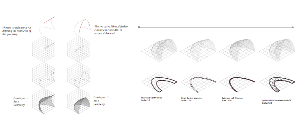
Various scale comparison for the wall thicknesses
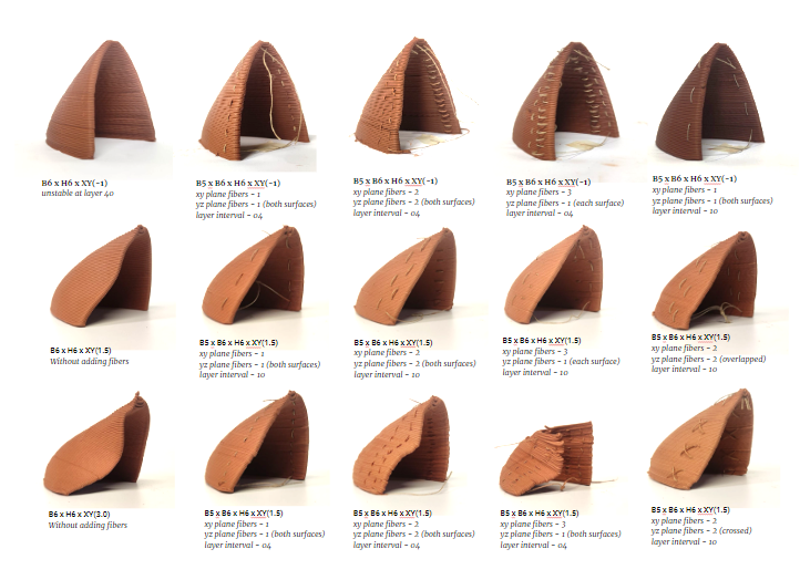
Identifying the potential locations for the fiber placement
Edge stability comparison with fiber placement patterns
Edge stability comparison with vertical fiber placement
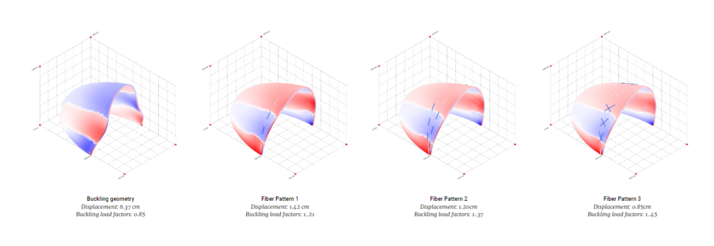
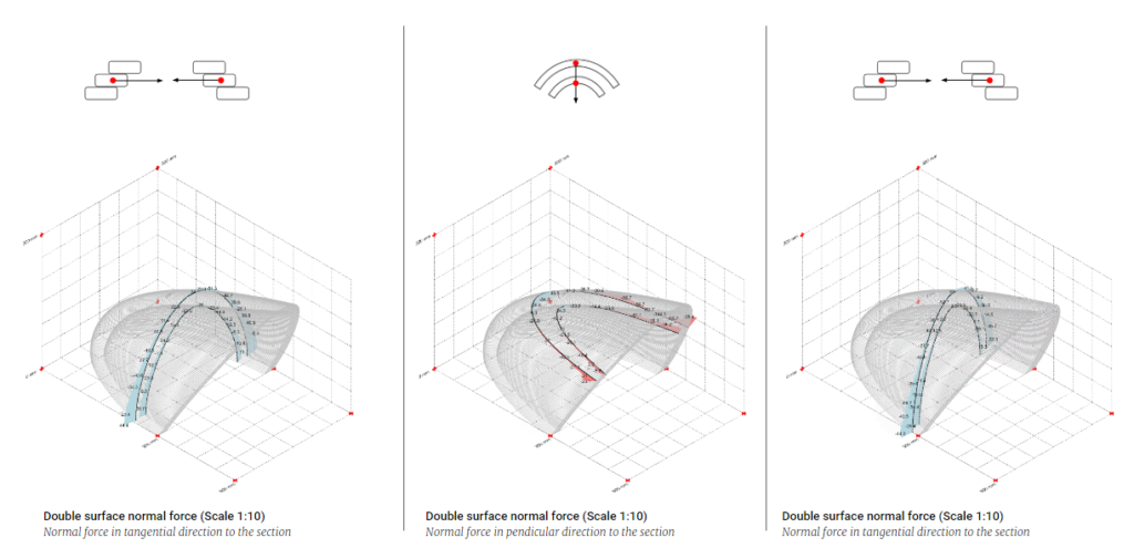
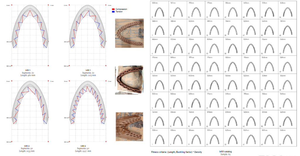
Karamba analysis of compression and tension zones during printing
Karamba fiber analysis
Karamba analysis of compression and tension zones during printing
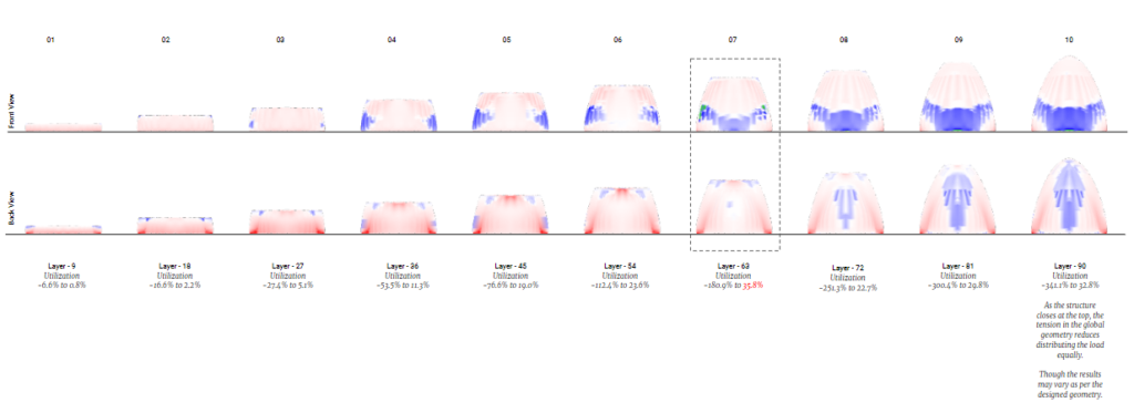
Karamba analysis of compression and tension zones during printing
Bounding Box300mm x 300mm
Edge stability comparison with vertical fiber placement
Infill to improve the printability of the geometry with the increasing cantilever
Edge stability comparison with vertical fiber placement
Bounding Box 100mm x 100mm
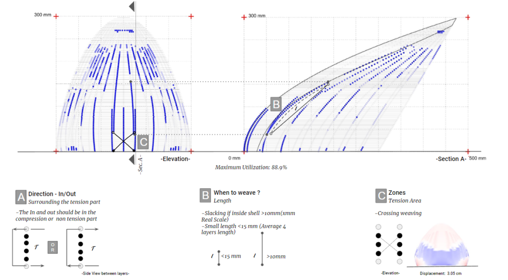
Weaving pattern from catalog conclusion and implementing in the optimized placement of the fiber.
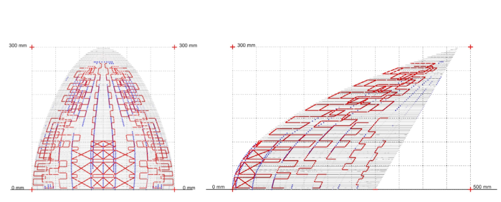
Fiber pattern display based on tension analysis
Fiber amount: 25
Length: 95.6 mm to 1360.3 mm
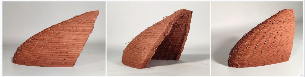
Scale – 1:12
Machine – ABB 140
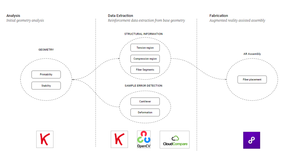
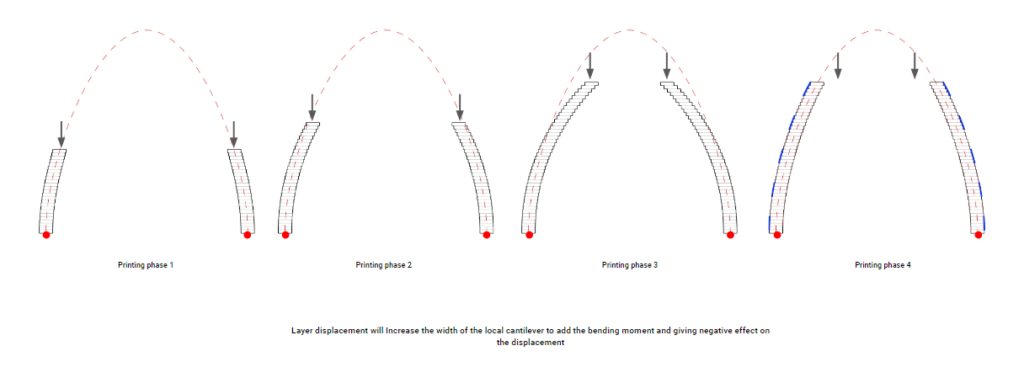
How the system work
