As an introduction to digital fabrication, a 3-weeks course was planned on new production techniques through the relation between computer data and machine-oriented fabrication. The aim of the course was to explore the design opportunities arising from three common digital fabrication processes: Laser Cutting, CNC milling and 3D Printing. We had to explore each technology and material, going through a conceptual and prototyping process of design each week.
01: Laser Cutting
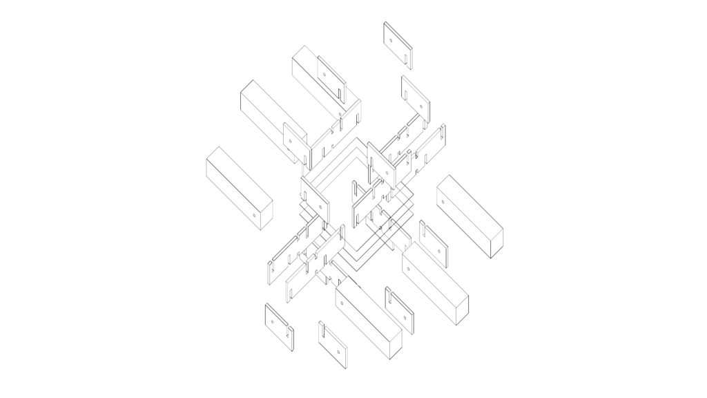
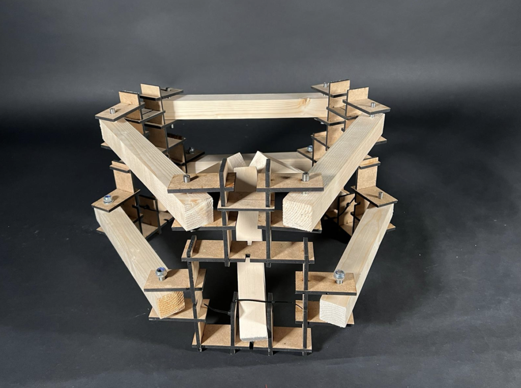
The goal of this exercise was to join simple recycled timber beams into informed and complex spatial structures that follow a specific constructive assembly logic ruled by spatial joints. The technique that we used was Interlocking, in which we produced a module that can be used to create different kinds of joints using the same piece multiple times. This kind of module can help to optimize file and help to explore the interlocking in more than one way to create different geometries.
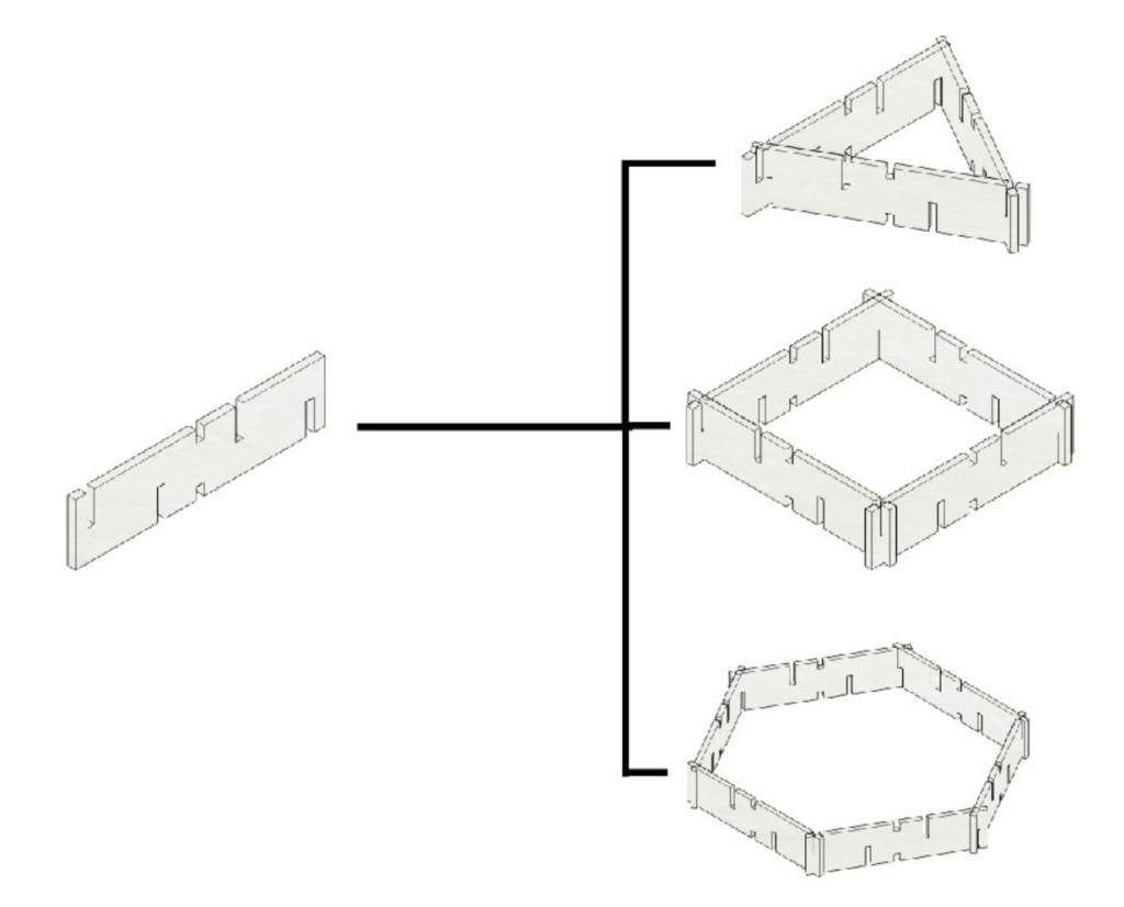
After exploring ways of connecting pieces of joint, to have both joint stability and timber movement, we reached a result.
Parameters:
Laser Cutter: Rayjet 400
Speed: 1.30
Power: 68
Frequency: 500
02: 3D Printing
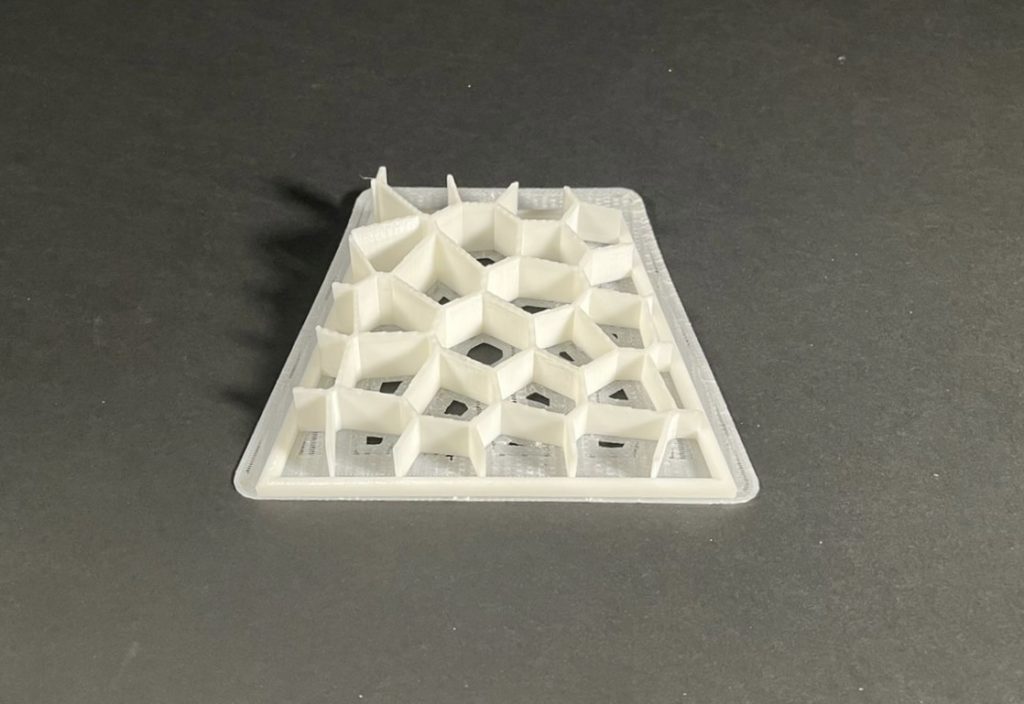
This exercise was about design and printing a model, and explore structural performance while minimizing material and maintaining adequate load distribution. This printed model had to be part of an architectural element with 1:1 scale.
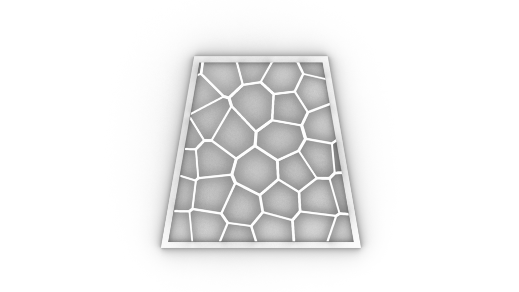
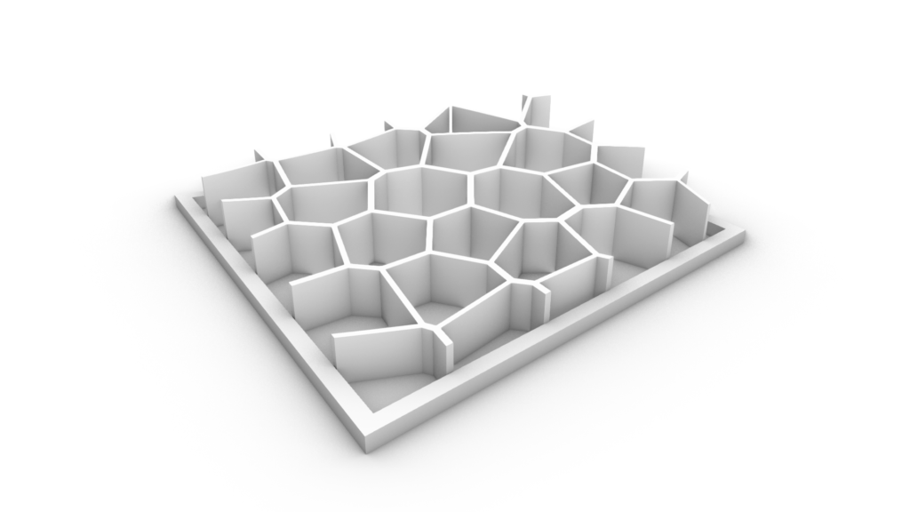
A pattern was designed and modeled with rhino to be a part of a facade. The change in height in different parts will cause shadows and reduce the effects of direct sunlight. Our design did not have any angles over 45 degrees which is the overhang degree. As a result we did not print any support. We printed a thin layer of raft underneath (4 layers) to maintain the stability on printer’s platform.
Printing Parameters using Z-suit software:
Printer: Zortrax M200+
Material: ABS2
Workpiece volume: 156x163x30 mm
Density: 3.50 mm
Nozzle diameter: 0.4 mm
Layer thickness: 3.9 mm
Pattern: Rectangular
Infill density: 20%
Raft layers: 4
Estimated Print time: 4h 50m
Material usage: 29.21 m (70g)
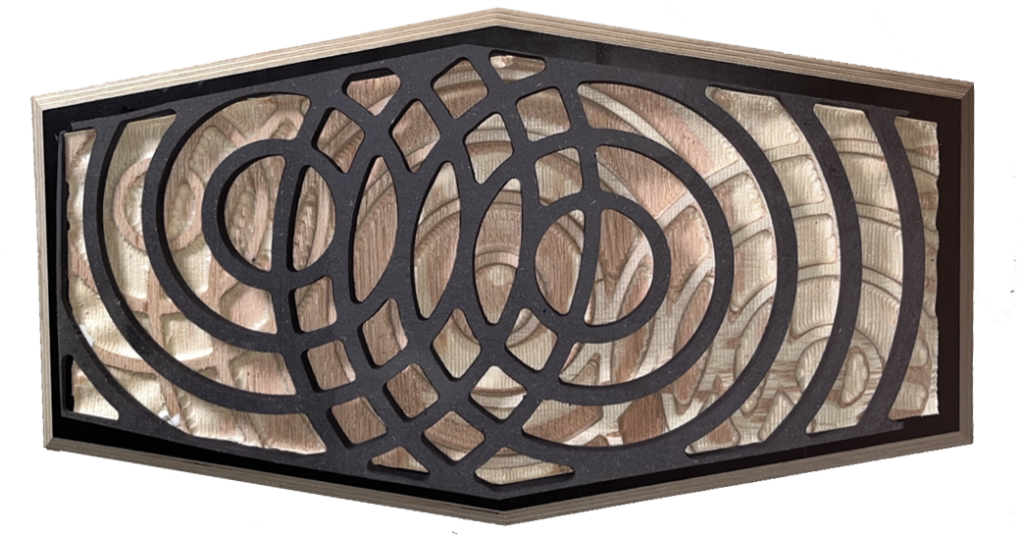
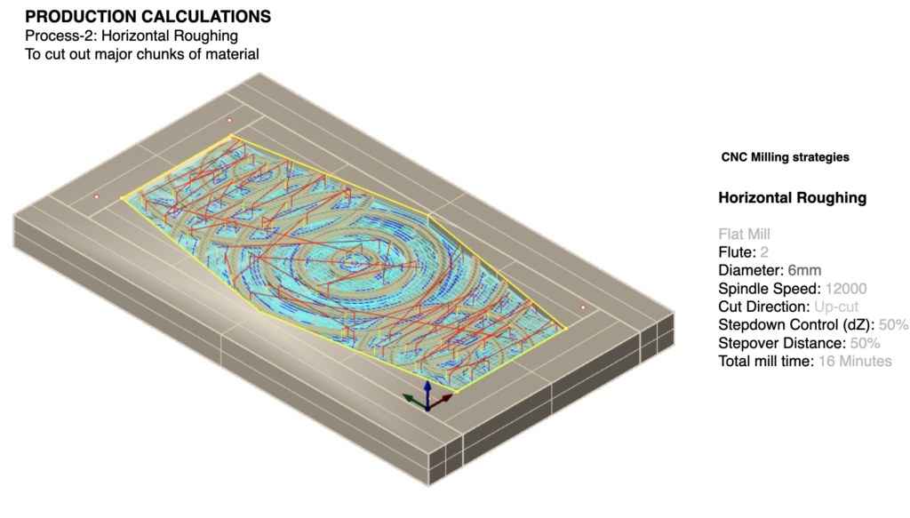
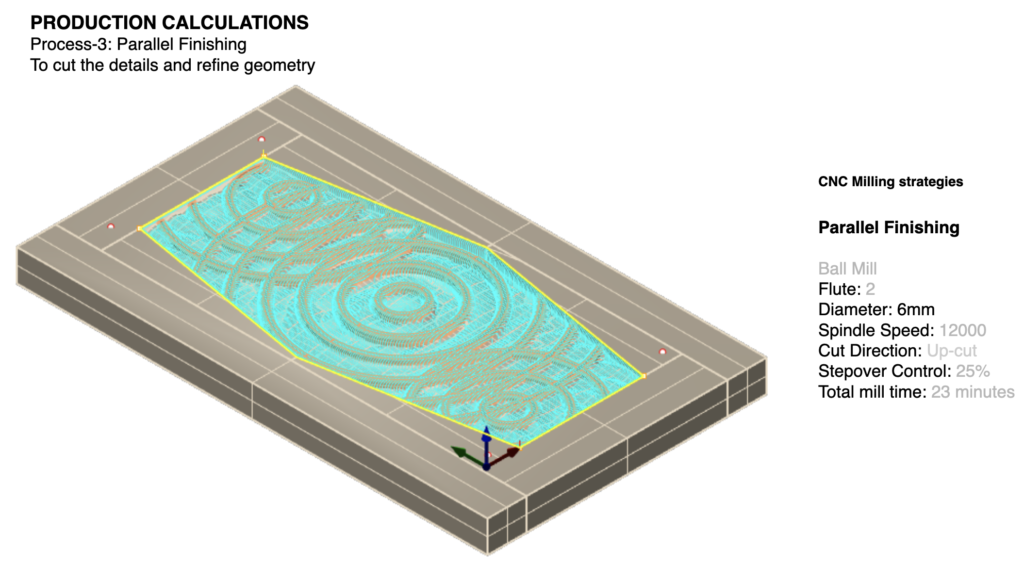
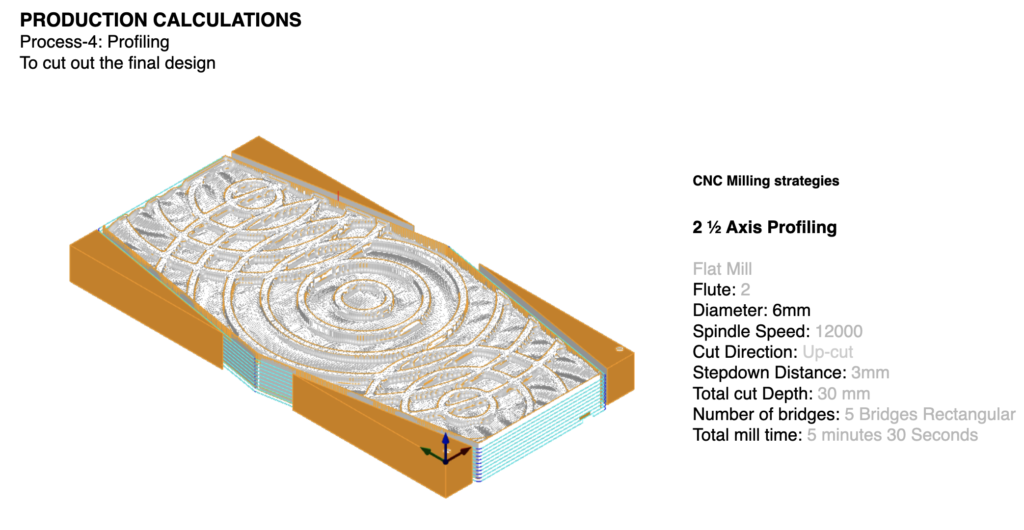
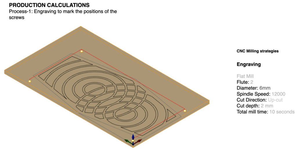
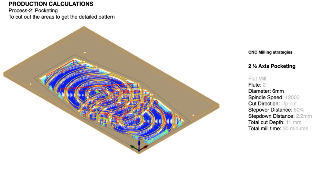
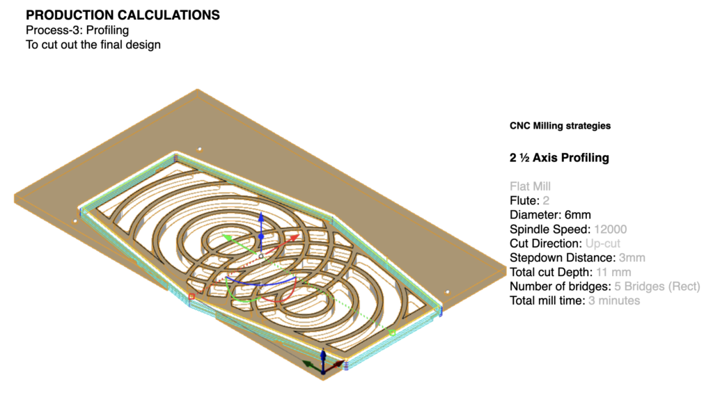
03: CNC Milling
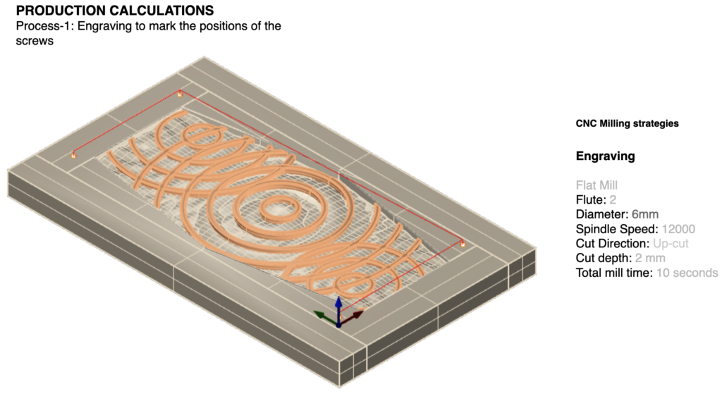
Aim of the project was to create a surface panel with concentric circles and wave forms, and making a 3d model of the same using cnc milling strategies in order to achieve aesthetic and clean cuts.
Material: 30mm Plywood, 10mm Black MDF
Machine: Shopbot
Post Processor: .sbp
Workpiece volume – 360x180x30mm, 360x180x10mm
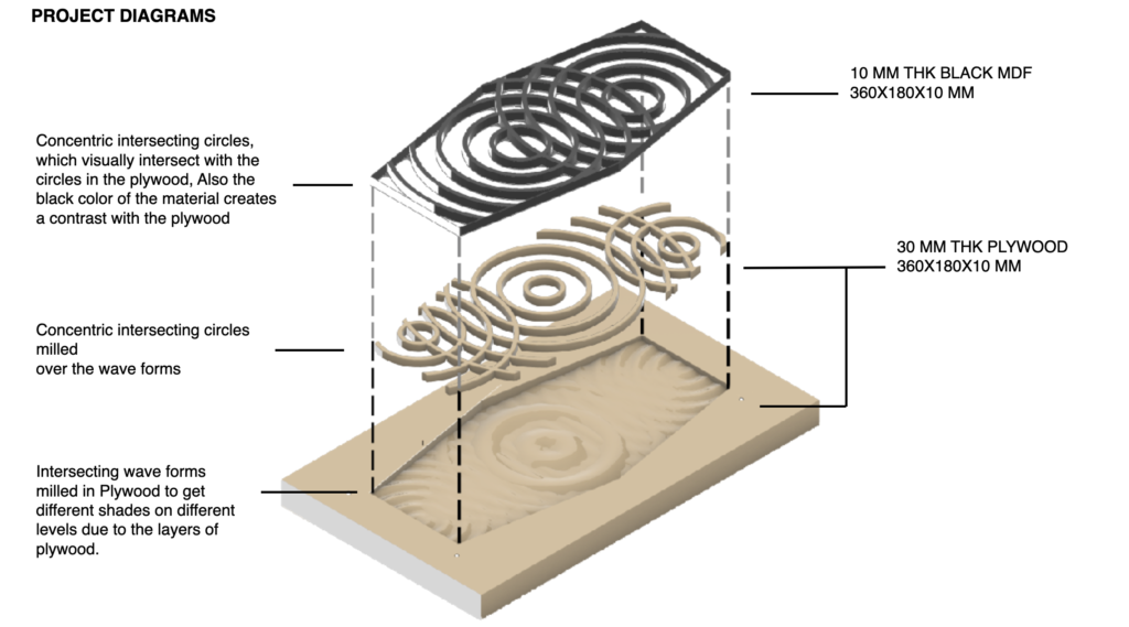
Plywood was used as a base material to get the textures of different layers, Plywood as a material experiences a lot of chipping, after sanding the Milled piece it gave a very nice textured finish, whereas, the black MDF did not need sanding and came out clean. The black MDF was chosen to create a contrast with the light plywood.