
Bringing Hyper Building A’s Complex Structure into Revit with Rhino.Inside.
Integrating Parametric Workflows in BIM
Hyper Building A is a collabortive project developed during the studio course on MaCAD’s 24/25 second term. As the structure team we had the task of creating and developing the hyperbuilding’s structural system. In the Integrative Modelling seminar, we developed strategies to translate the complex project geoemtries we created parametrically in grasshopper into a Revit project we could update and document.
Structural Concept: Merging Flow & Stability
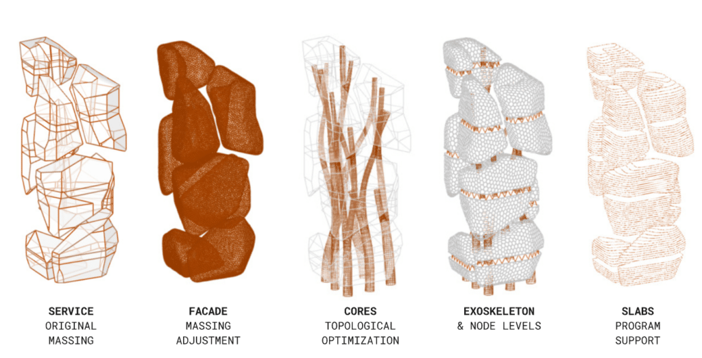
The design of Hyper Building A is guided by the principle of flow, integrating both circulation and structural logic. The floating neighborhoods rest on a system that distributes loads dynamically through:
- Core System: A series of topologically optimized cores, which also seve as circulation system and balance the building’s weight and forces.
- Node Levels: Triple-height space frames that redistribute forces across neighborhoods.
- Exoskeleton: Serving both as a facade support and additional structural reinforcement.
By integrating these components, the structure not only supports but also connects the different neighborhoods, embodying both structural efficiency and architectural intent.
From Parametric Design to Revit: The Workflow
Bringing this complex structure into Revit required a multi-step workflow:
- Base Massing & Structural Elements – We started with an initial massing from the service and industrial teams, using it as a foundation to model slabs, cores, and node levels in Grasshopper.
- Geometry Preparation – Different types of elements required distinct approaches:
- Slabs & Supports were modeled using curves.
- Cores were created as Sub-D geometries to maintain smooth structural transitions.
- Node Level Elements were defined as curves for better parametric control.
- Rhino.Inside Revit Integration – When transferring geometries, we aimed to retain as much data as possible, but complex elements like perforated slabs and the exoskeleton posed challenges. To resolve this, we opted for DirectShapes for intricate components while successfully importing optimized cores as beam elements using their mesh edges.
- Linked Model Strategy – Given the computational weight of the project, we divided the model into linked Revit files, categorizing:
- Cores
- Exoskeleton
- Facade .
- This allowed us to load/unload elements dynamically, optimizing performance while working on documentation.
Evolution of the Model & LOD Adjustments
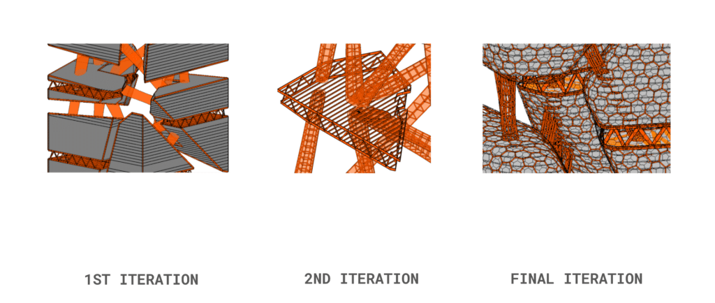
Over the course of the seminar, we progressively refined the structural representation:
- Initial Stages: Simple breps outlined the neighborhoods and core structures.
- Refinement Process: As we progressed, the model transitioned to fully detailed structural elements, increasing the Level of Detail (LOD) in alignment with BIM requirements.
- Final Iterations: The neighborhoods became collections of structural components rather than single breps, improving their integration into Revit’s system.
Documentation & Visualization
A key goal was ensuring clear structural visualization in Revit. To achieve this, we structured our sheets to emphasize core structural elements:
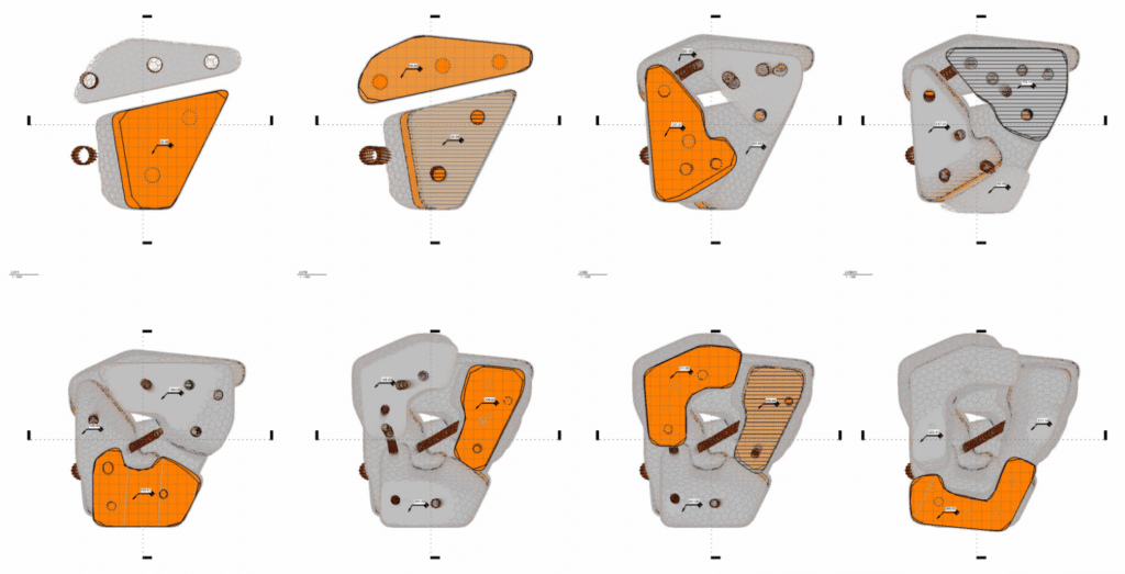
- Floor Plans: Generated every 20 levels to provide a sectional understanding of the node levels.
- Sections & Elevations: Showcasing the exoskeleton and facade in relation to the internal structure.
- Axonometric Views: Highlighting how node levels, cores, and the exoskeleton interact to support the neighborhoods.
- Detailed Neighborhood Views: Focusing on individual neighborhoods, illustrating their structural composition and connections.
Challenges & Lessons Learned
Throughout this process, we encountered key insights:
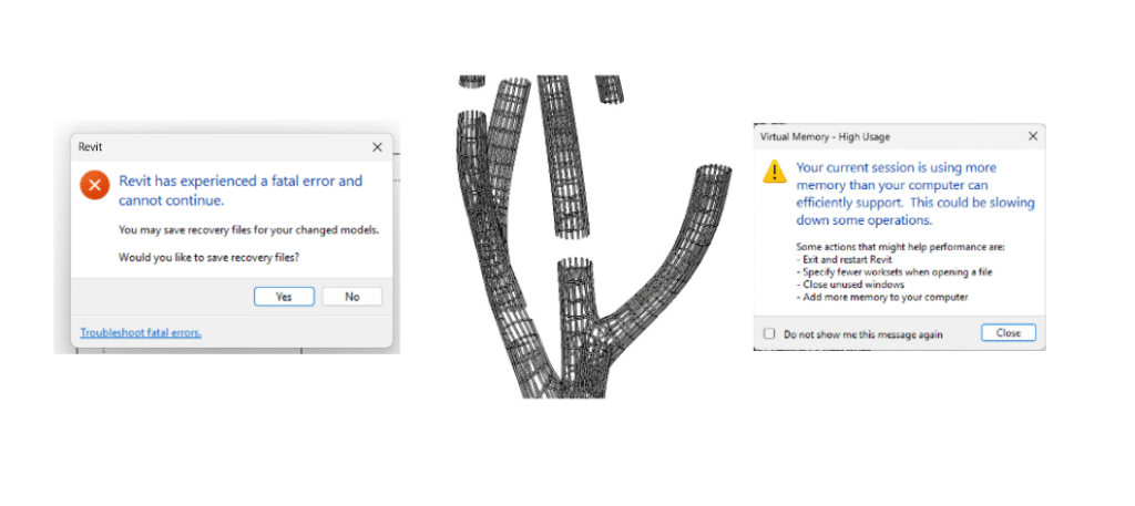
- Revit is powerful for categorizing and visualizing structural elements, but as the model complexity increased, so did computational challenges.
- Rhino.Inside enabled parametric geometries to be translated effectively, but some intricate forms had to be adapted for seamless integration.
- Linked models helped manage performance, but with the growing level of detail, data-heavy elements required strategic simplifications.
Ultimately, this process demonstrated how parametric workflows can be successfully integrated into BIM environments, enhancing both design flexibility and documentation precision. Hyper Building A’s structural system serves as an example of how complex architectural geometries can bridge the gap between computational design and real-world BIM applications.
