
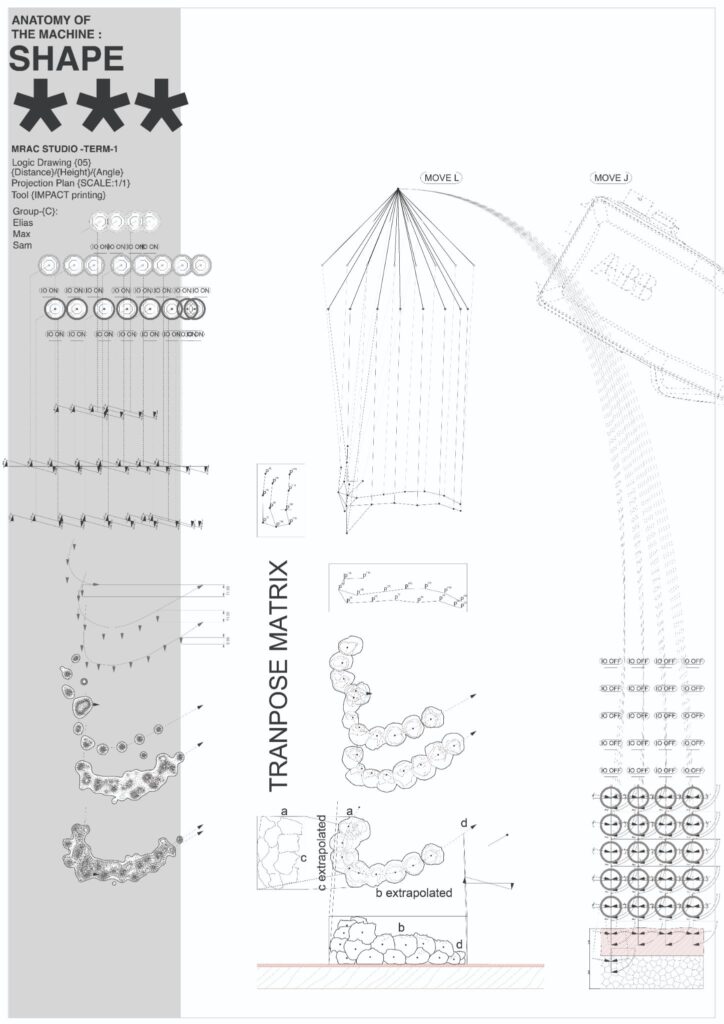
Anatomy of the Machine:
Impact Printing
abc
What is Impact printing?
Whilst clay has been used as a construction method for thousands of years, with evidence of buildings dating back to as early as 9000-10,000 BC in Mesopotamia, impact printing is a extremely modern take of the additive construction process.
Research particuarly at ETH Zurich from a clay slinging (2014) and more recently by Gramazio Kohler at ETH (2021 – onwards) has began to explore the technique further.
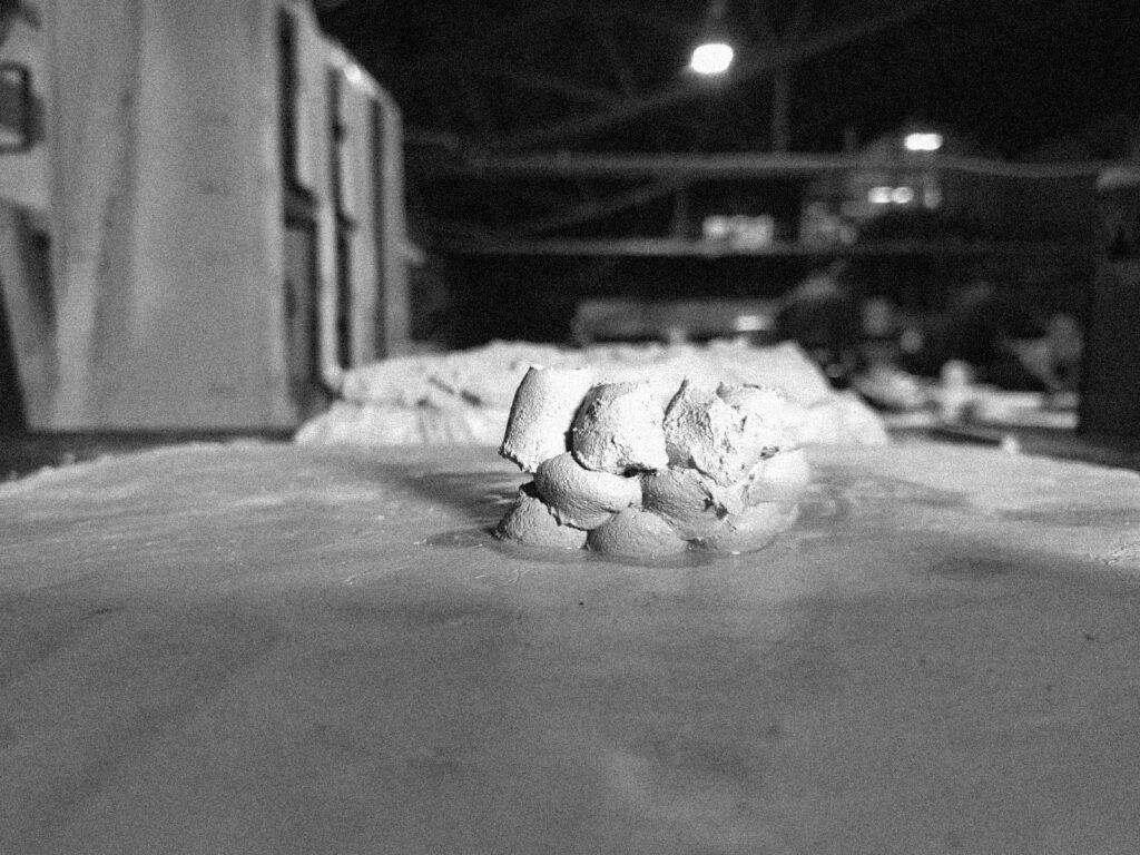
Impact printing works by projecting clay additions into a mass at high velocity. Using the kinetic energy to create strong, integral forms without the clay having to be baked.
For this project we used an IO activated piston attached to the ABB 120/140 to fire the clay pellots out of 20mm diameter acrylic tube with a PSA of 4.0
Testing
Manual Attempts
Our first steps involved manual discussions for a path along an arch frame which could then be removed afterwards.
Slip and platform
Having moved from manual prototyping to the robots we quickly discovered that several variables needed to be edified for the tool to be able to pick and shoot the clay pellets.
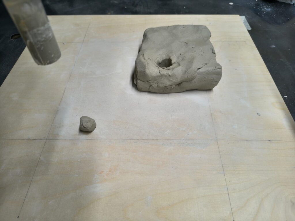
In order to solve this we added both a slip to the placing board. A thin layer of wet clay for the first layer of pellets to stick to. For the picking the tool could not seperate the clay without fully penetrating the feed, however, to allow this as a path would lead to a joint collision with the tool into the table. As a solution we raised the clay onto a 30mm styrofoam board. With this the tool could collide without breaking.
Control variables: Height
Now we could pick and shoot the material, we quickly began to analyse and understand the path parameters which would affect the outcome of printing. First, testing height we discovered with the tool there was an optimal 6-10mm Z-distance from the slip to the TCP as a placing parameter. Lower would mean residue stuck to the tool and higher meant pellets not sticking to the board.
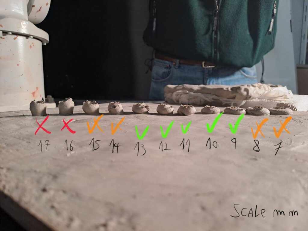
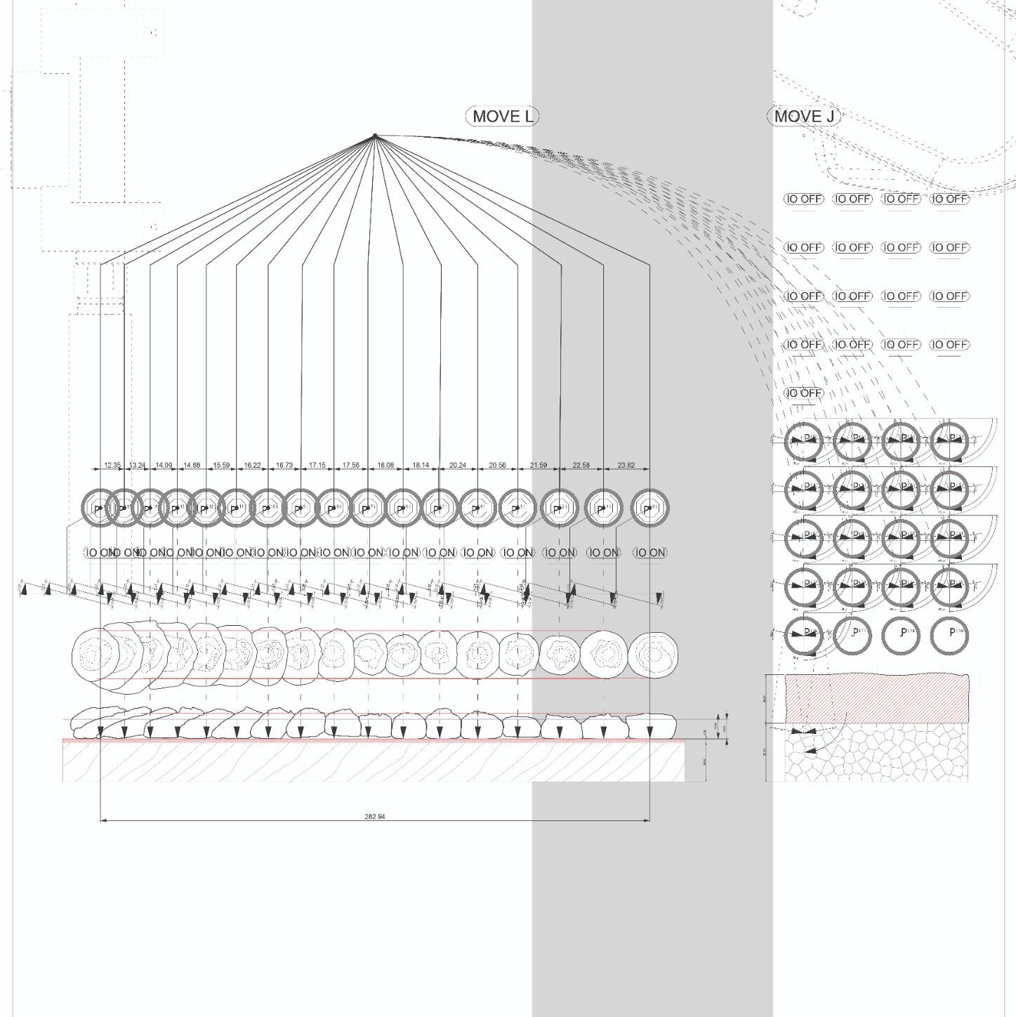
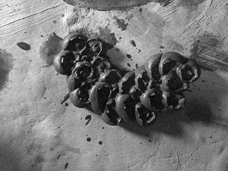
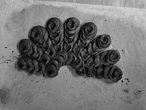
Control variables: Stepping
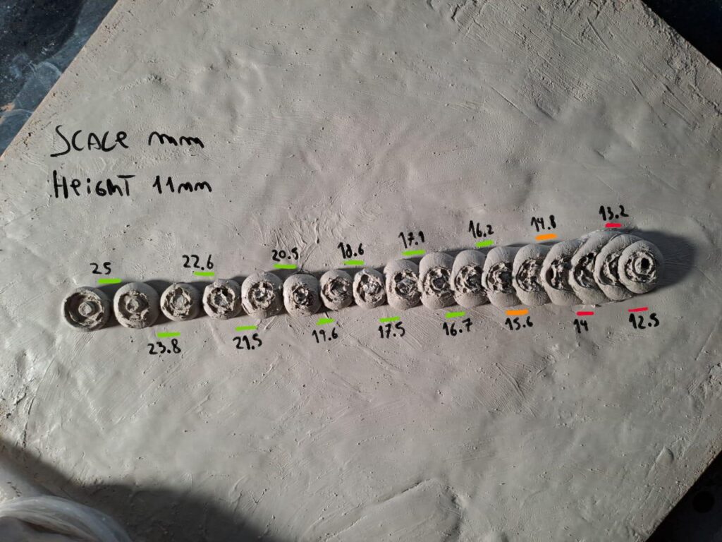
Secondly, we tested the stepping distance; this was in response to our first set of trials with height, as we found the more ideal shooting distance of 6-10mm (for first layers) produced a pellet typically 25mm in diameter.
We wanted to see how the spacing between each of these would affect the binding of two adjoining pellets from a start where they were seperated to the extreme overlay as visible from left to right on the next image. This helps us to understand the quality of how a path would have to be constructed for our final outcome.
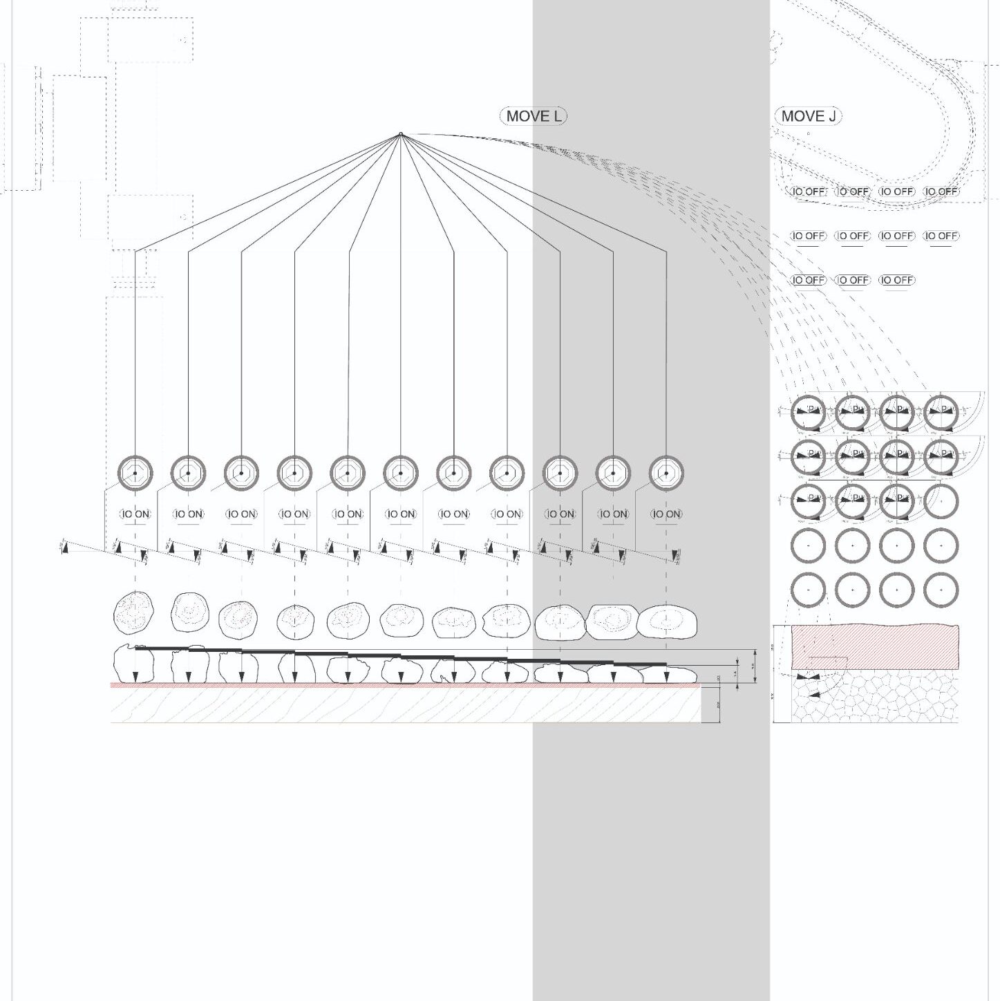
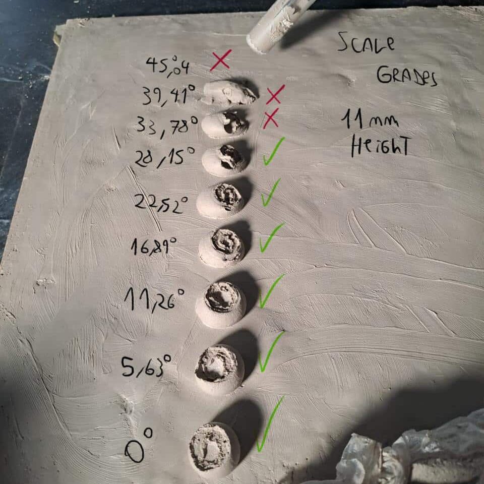
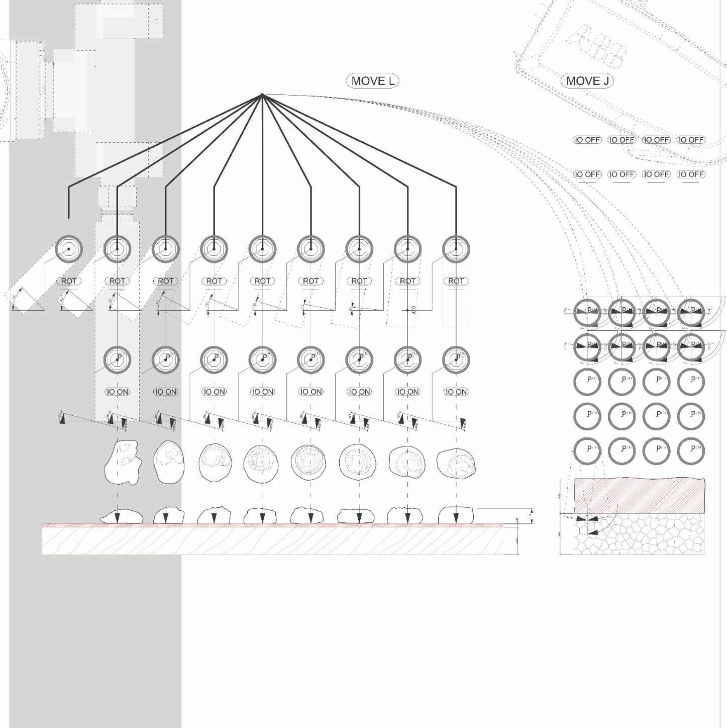
Control variables: Euler angle
The next question which we wished to address, especially within the scope of using the tool with a 6-axis robot was how rotation would affect the sticking of the clay. We wondered if by forcing extreme angles we could better manipulate the sticking of some pellets to pre-fired ones. In our first tests, we found that keeping to the ideal height of 6-10mm we were limited to a maximum rotation axis of +/-30 degrees, any more would risk tool collisions.
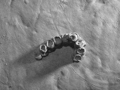
Stacking
The last parameter we wished to explore before trying our final iterations was stacking the placed pellets on top of each other.
Using what we had learnt from the previous tests for height, angle and stepping we were able to create a layered structure with different parameters across its design and discuss which parts we thought worked best and could be potentially intergrated into the final version.
Final Iterations


Iteration 1:
Iteration 2:
Iteration 3:
Angled / Height / Stacking
Angled / Height / Stepping
Angled / Height / Stepping / Stacking
In our final iterations we chose to explore a mix of what we had learnt from our tests and more complex robotic paths which would challenge these limitations further.
