
The focus of the project is to develop a new school for the city of Manchester. Much of the recent construction boom in the city has focused on high-cost luxury accommodation, leaving a gap in the provision of essential community amenities. Our proposal aims to address social concern by advocating for the establishment of a school, library, and other vital facilities designed to serve the needs of the local community.
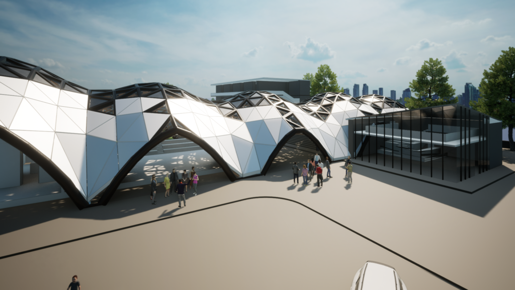
Figure 01: Concept image of proposal
The project seeks to provide a framework for wide scale adoption of timber construction in England through the establishment of local supply chains – a popular practice in parts of Europe. It aims to assess the sustainability, economic viability, and structural feasibility of GLT within England’s construction industry.
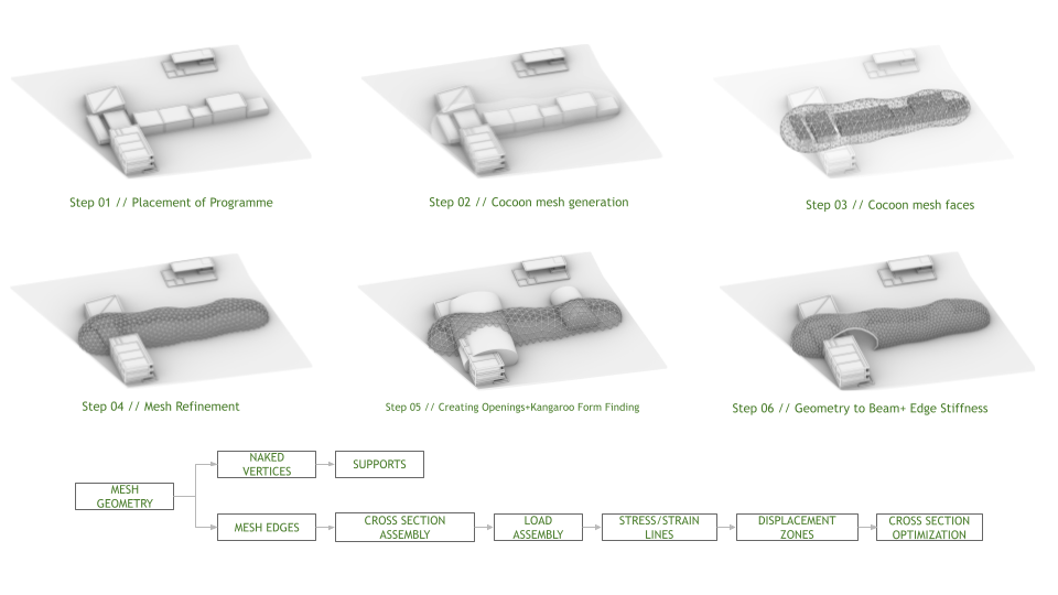
Figure 02: Conversion of geometry into Structural FE Model
The design process starts by placing the program in relation to contextual information and requirements. Cocoon (a grasshopper plug-in) is then deployed, utilising the central points of the volumes to create a continuous skin. This process leaves us with our desired form above ground but still requires some refinement. The mesh is then cut using the topography and the mesh refined using the tri-remesh component from Kangaroo. Volumes are then used to cut openings where desired. The process then diverges to allow for the exploration of alternate grid types. The mesh geometry is then converted into different structural elements to be analysed in Karamba. Finally, edge beams are introduced to provide stiffness where required.
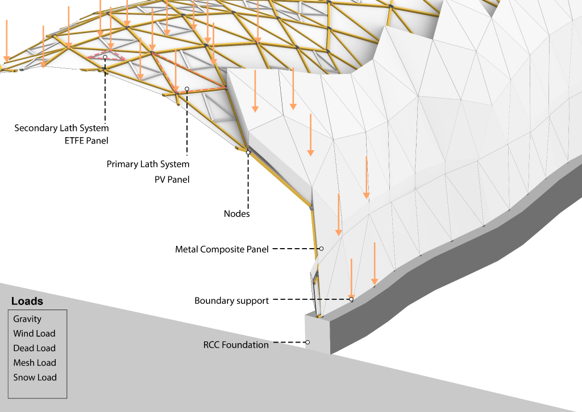
Figure 03: Structural diagram of chosen system
Load is transferred through the primary structure containing the lathes and nodes to the edge foundation supports as shown. Secondary structure helps to support different panel systems. The image also shows the load considerations when setting up the analysis model.

Figure 04: Image showing the optimsation process
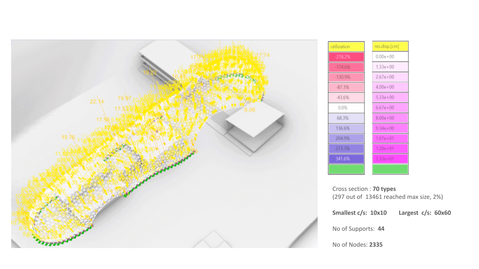
Figure 05: Tri-Grid Analysis
This image shows the optimisation process for the tri grid, taking into account the stress/strength ratio, maximum displacement resulting optimal cross section length and sizes for the lathes. The same the process is carried out for the quad mesh.
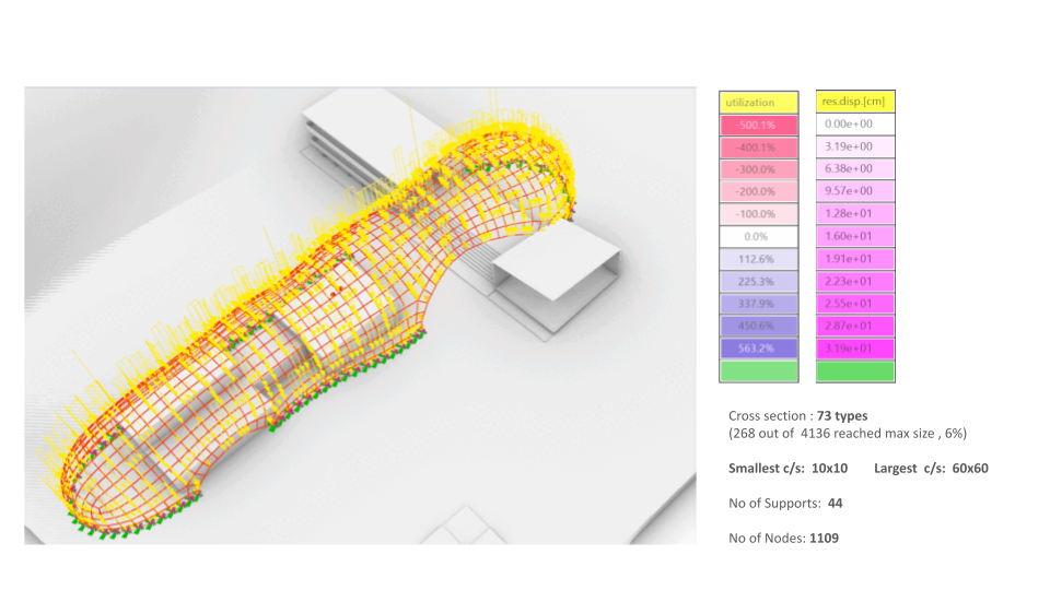
Figure 06: Quad-Grid Analysis
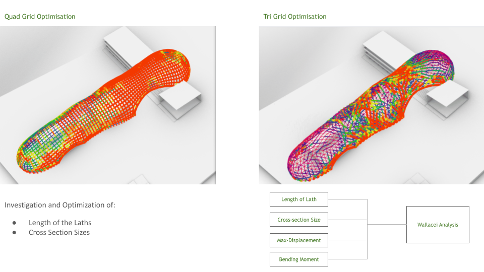
Figure 07: Wallacei Optimization
Utilising Wallacei multi objective analysis, we were able to explore the optimization of the cross sectional sizes and lathe lengths whilst reducing the maximum displacement and bending moment. From this we find that the quad grid has the best performance in terms of a standardized lathe dimensions.
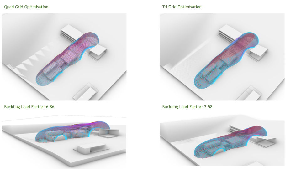
Figure 08: Buckling load factor
To provide structural stability to both system, the integration of edge beams on the periphery were explored using Karamba. We found that quad grid performed better as shown.
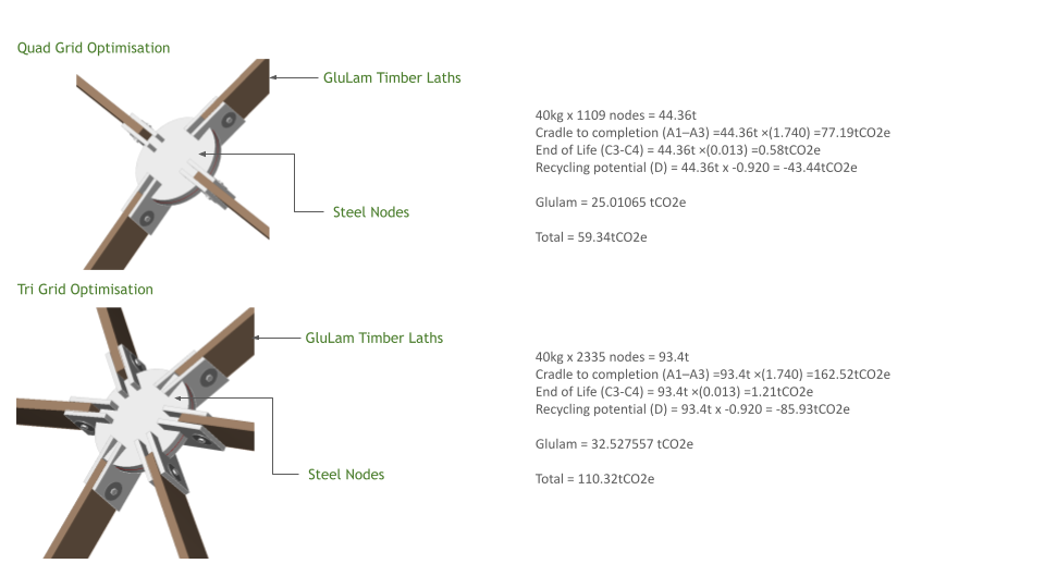
Figure 09: Life cycle carbon assessment
The generated geometry was then used to calculated the life cycle carbon impact of the structure. Yet again, the quad-grid was found to outperform the tri-grid. Based on the cumulative findings of our analysis, we have determined that quad grid would best suited in terms of performance. In future work, we would hope to explore different forms to gain a greater understanding of where different grid types are most suitable and perform best.
