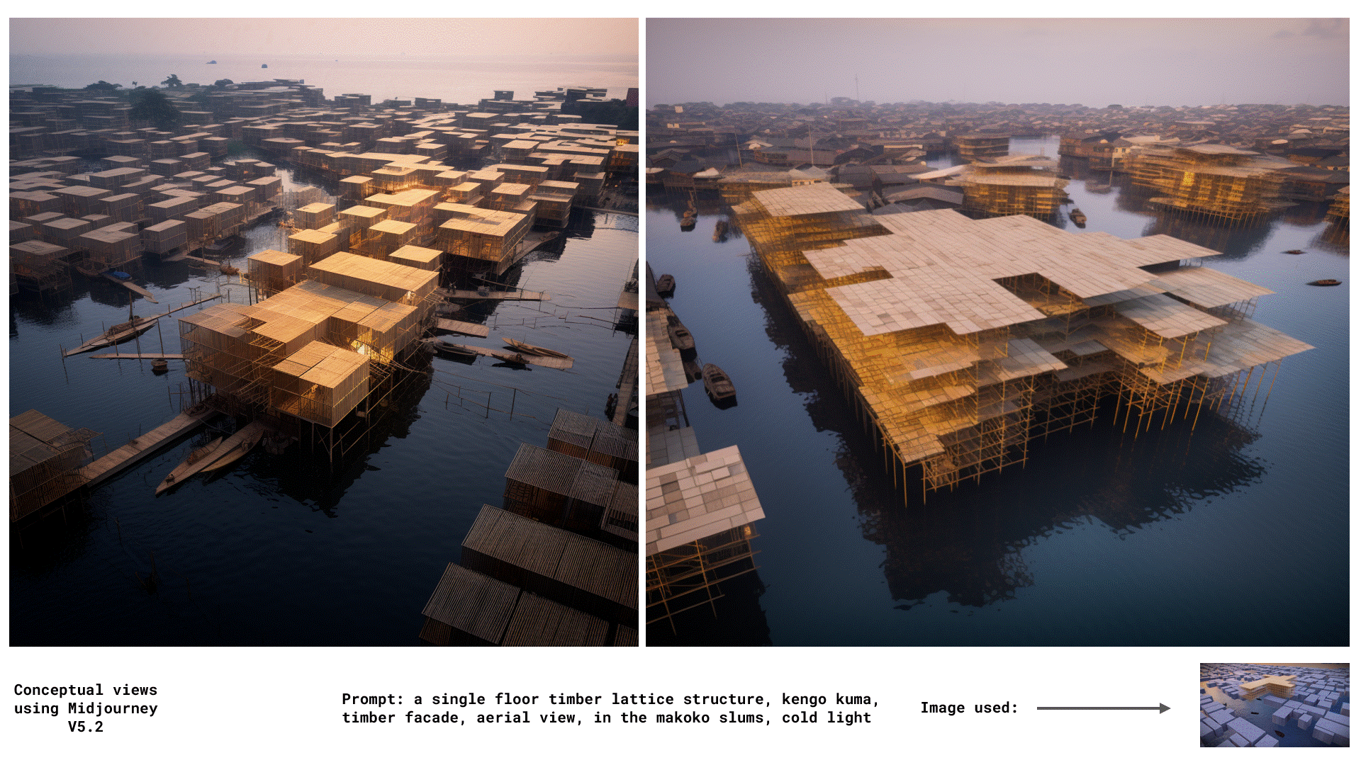
Adaptive and Modular Lattice Structure in Makoko, Lagos
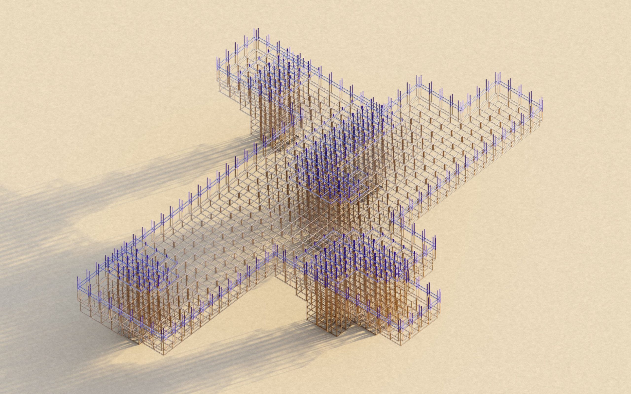
This project investigates a lattice topology constructed with timber elements. Through optimization and site selection a modular and adaptive system was generated for the chosen location.
STATE OF THE ART
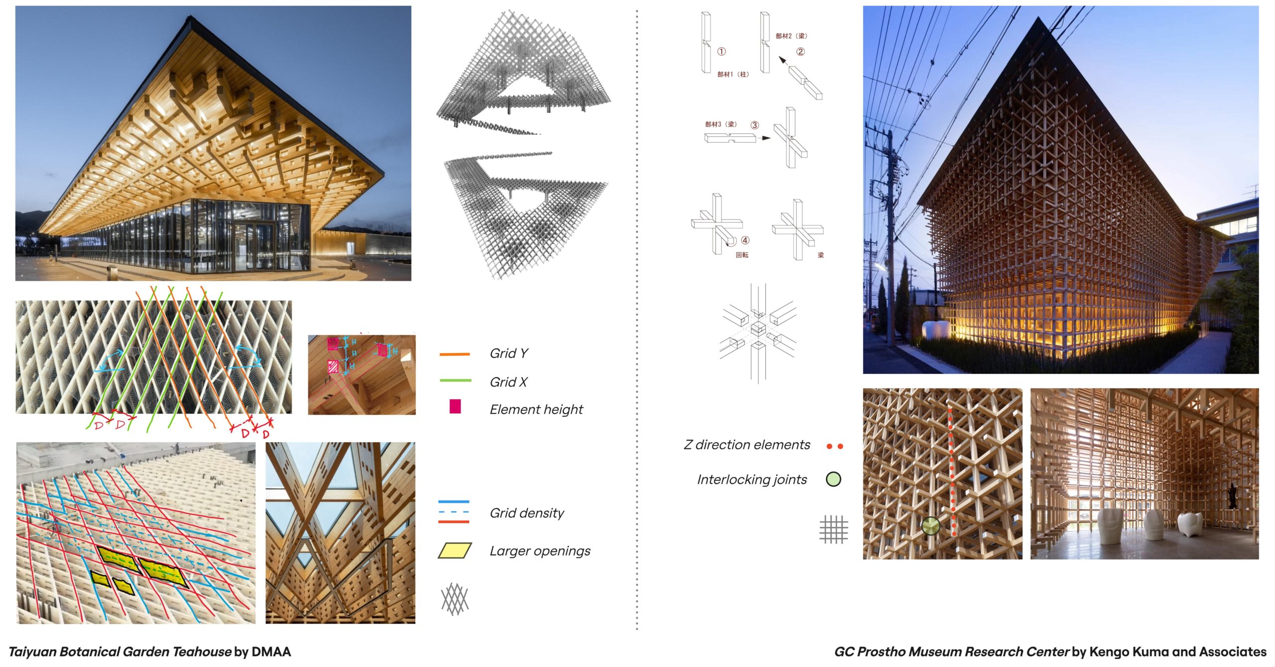
The chosen reference projects emphasize on specific grid formations, element size and direction, density and interlocking joinery. Within the system it is attempted to combine and parameterize these tectonics in a way that can be altered and modified according to various requirements.
SYSTEM PARAMETERIZATION

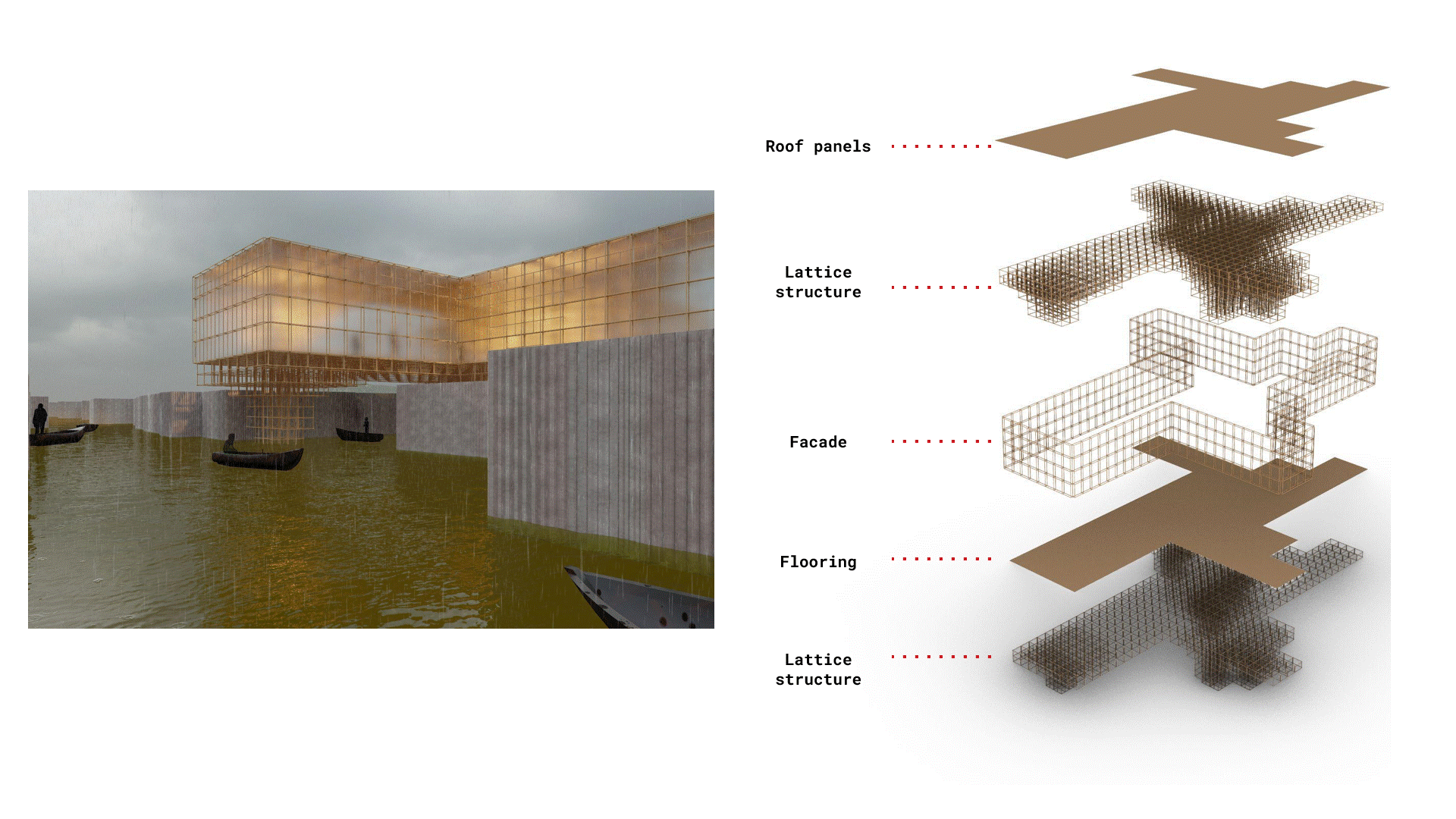
For the parameterization of the system the inputs were point, grid module size and element size. From point the boundary polyline is found, the grid size is selected to filter footprint from the boundary lines which then generate the floors. The footprint grid also attains the internal walls used for the structure and facade which is then optimized in Karamba.
SYSTEM MATERIALIZATION
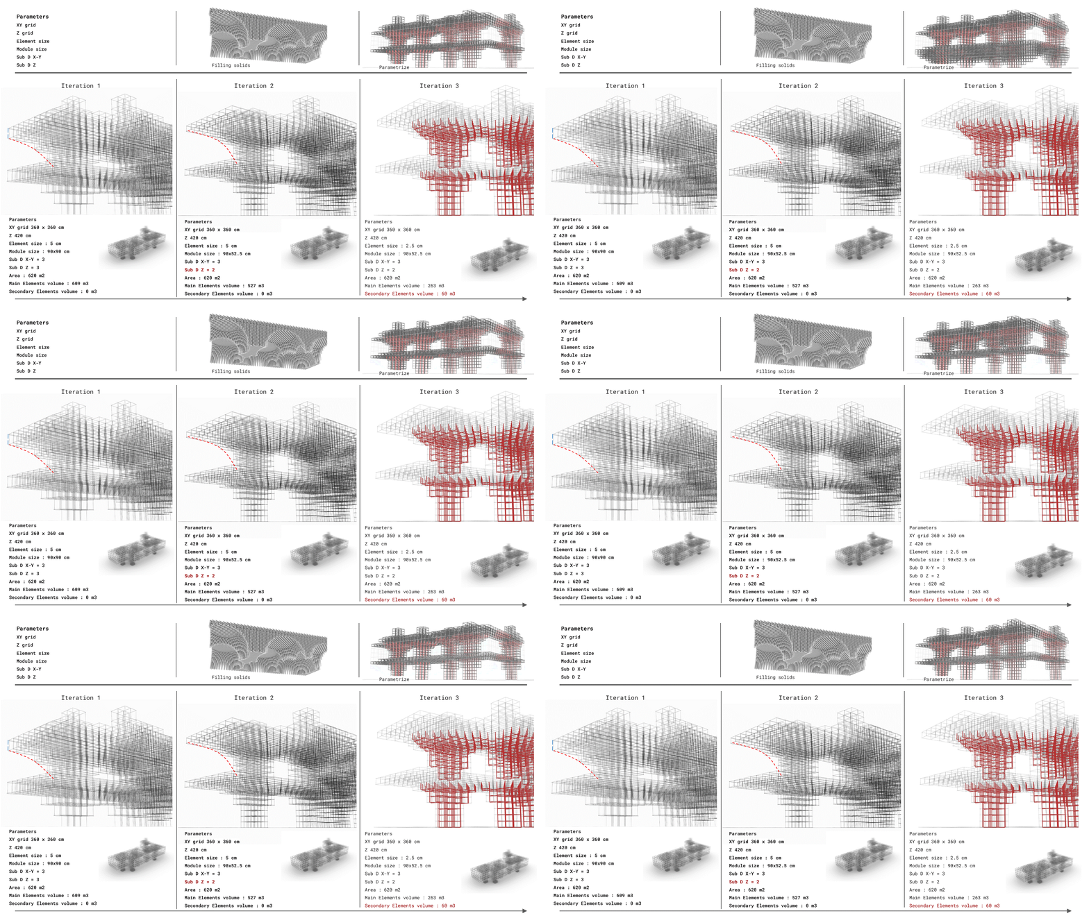
From lattice to building – density control

In order to materialize the lattice system into a building, an optimization process using Karamba and Wallecei was ran to find the internal walls that were most suited to be structural walls within the building in which the structure can grow from. Within the optimization process it was aimed to find the best location for the structural walls that will have minimum displacement. As the building is a modular structure it was aimed to keep the same size for each module of elements. Instead of having larger modules, more elements were added within the critical areas such as the structural walls and floors by finding the areas with maximum displacement.
SYSTEM MATRIX
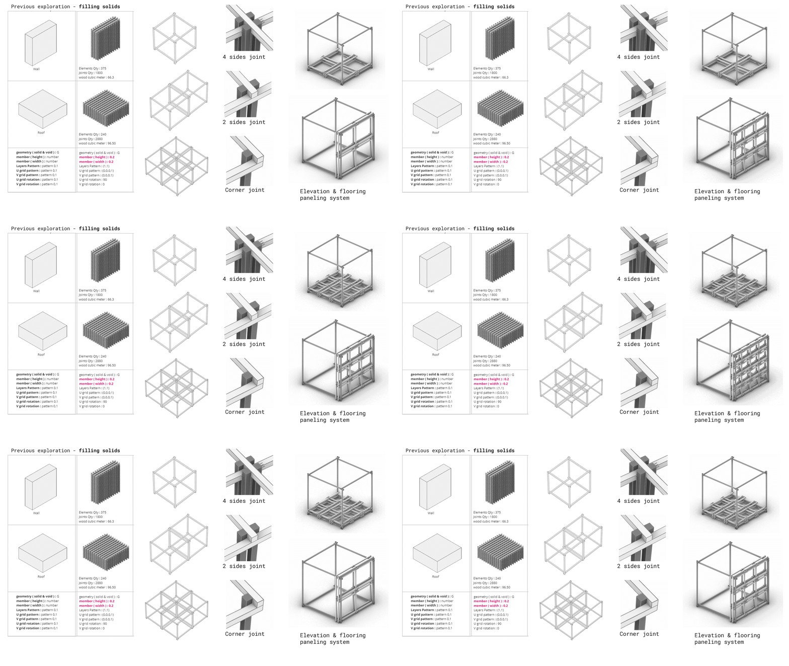
In previous explorations it was attempted to create a solid geometry, where the solids and voids were defined with the solid areas being the lattice elements. This exploration did not fully achieve the flexibility desired for the system. Hence to access the system in a more adaptive and growing method, the parameterization was changed to give more possibilities to control the elements. It can be seen how the changing parameters affect the material usage in the system from left to right.

CONTEXT
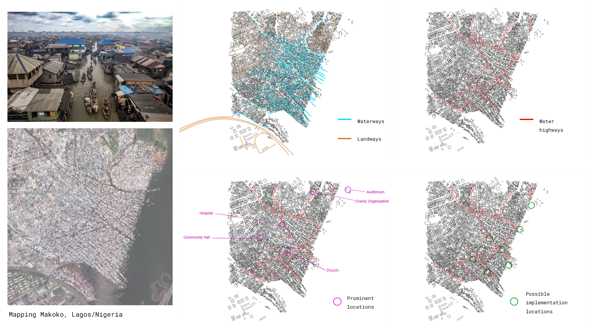
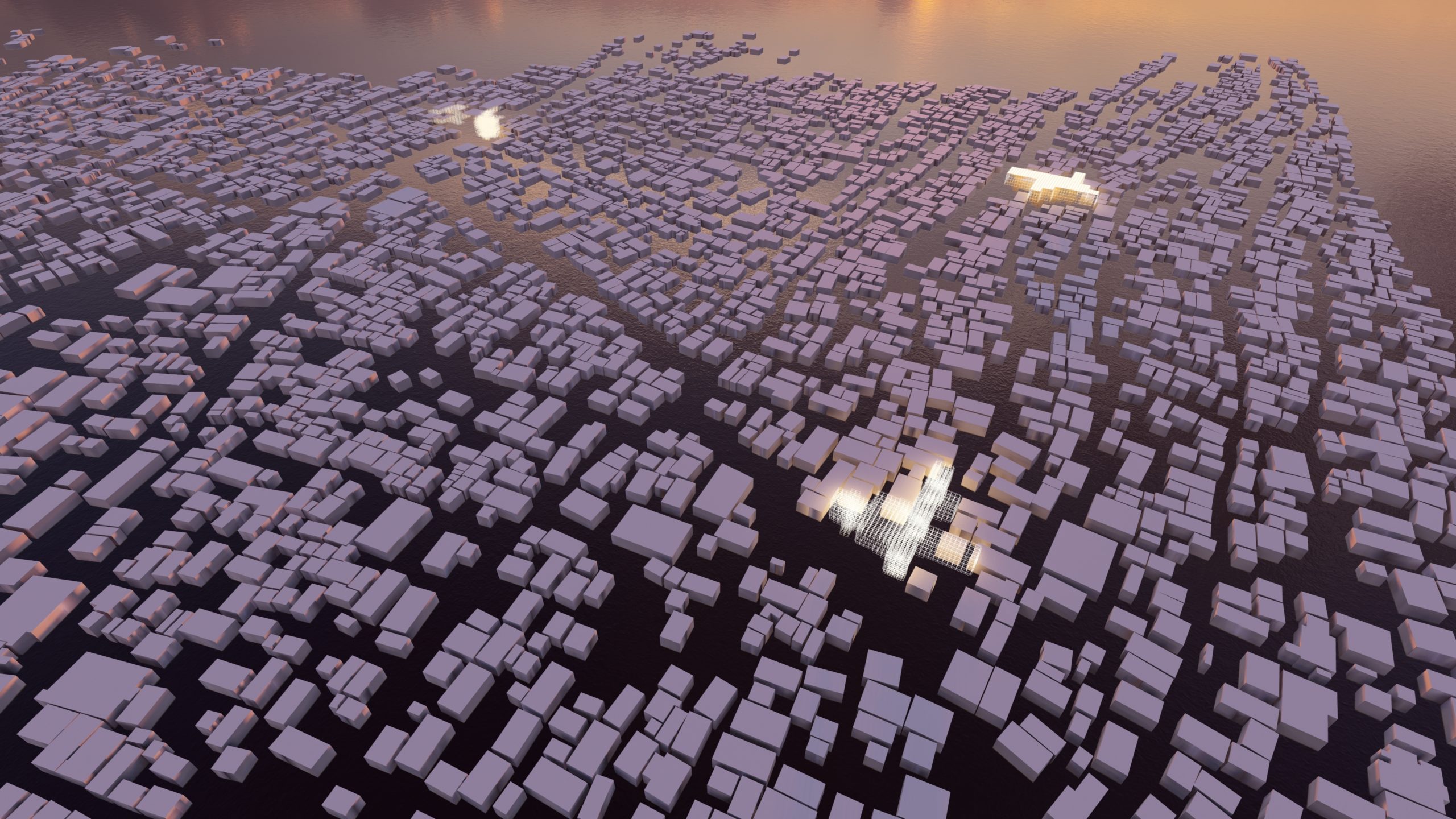
The chosen context is the Makoko settlement in Lagos, Nigeria. The area faces many challenges such as inadequate infrastructure and temporary informal housing appears wherever there is a vacancy. With this idea, through the lattice system a solution that can be tailored to the specific needs of the Makoko was visioned. By mapping the informal houses, the water and landways, the main water highways used for circulation, and prominent locations serving the community, the contextual parameters were set to pick specific building locations.
SYSTEM ADAPTATION
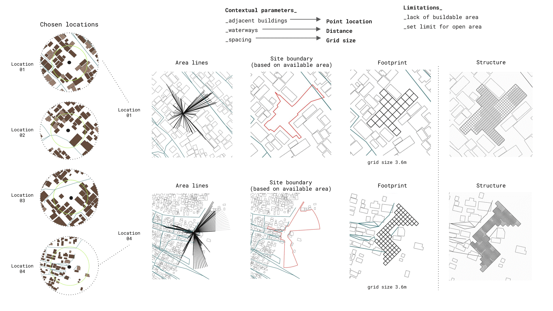
4 possible locations were chosen to test the lattice system. From the adjacent buildings the point locations were defined, and with grid sizing the distance from the waterways, prominent locations and spacing of the structure. The point sets the area limit for the boundary of the structure which then determines the footprint area which creates the lattice structure.
MATERIAL TRACE-BACK
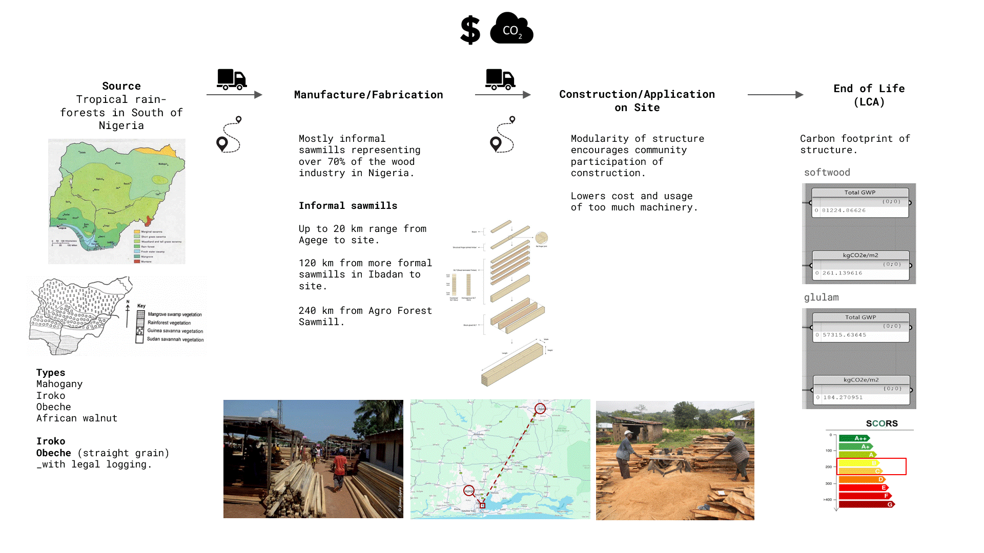
Nigeria is the largest timber producer in Africa and has tropical rainforests in the south which provide rich timber resources. Iroko and Obeche wood were chosen to be used in the structure as they both offer economic and ecological advantages which make it ideal for outdoor use. Informall sawmills represent over 70% of the wood industry hence it would be cost and carbon efficient to take advantage of the ones in close proximity to the site. In construction the modularity of the structure encourages community participation for application on site. The carbon footprint of the structure is calculated from the GWP being 260 for softwood and 184 for glulam giving a B to C SCORS value.
PLAN
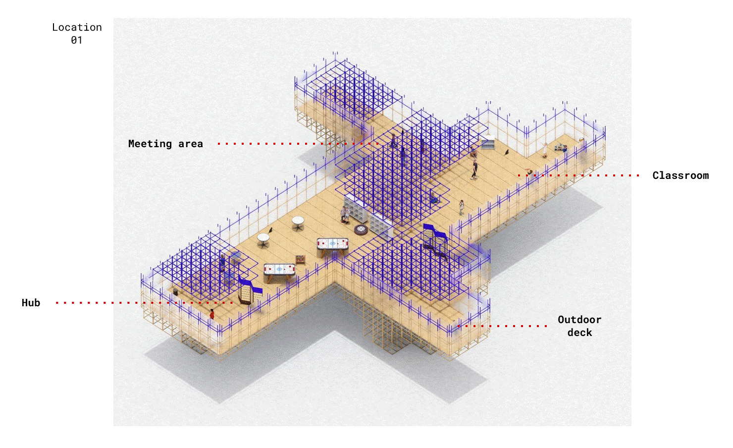
The defined functions are a community and central hub for meetings, class rooms/learning spaces and events. This fosters community cohesion, provides a space for dialogue on common issues and promotes civic engagements. The openness with wall partitions lets more flexible community defined areas. Here it is divided into meeting areas, classrooms and a common hub.
SECTION
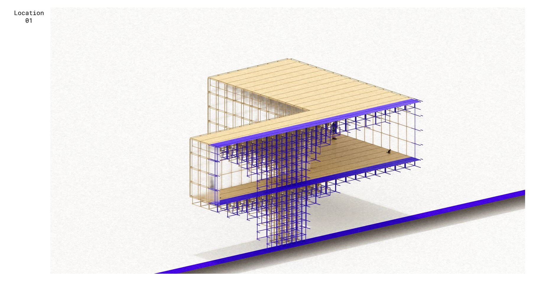
AXONOMETRIC
VISUALIZATIONS

