
MaCAD 23/24 // ACESD Digital Tools for Structural Optimization
Architectural System
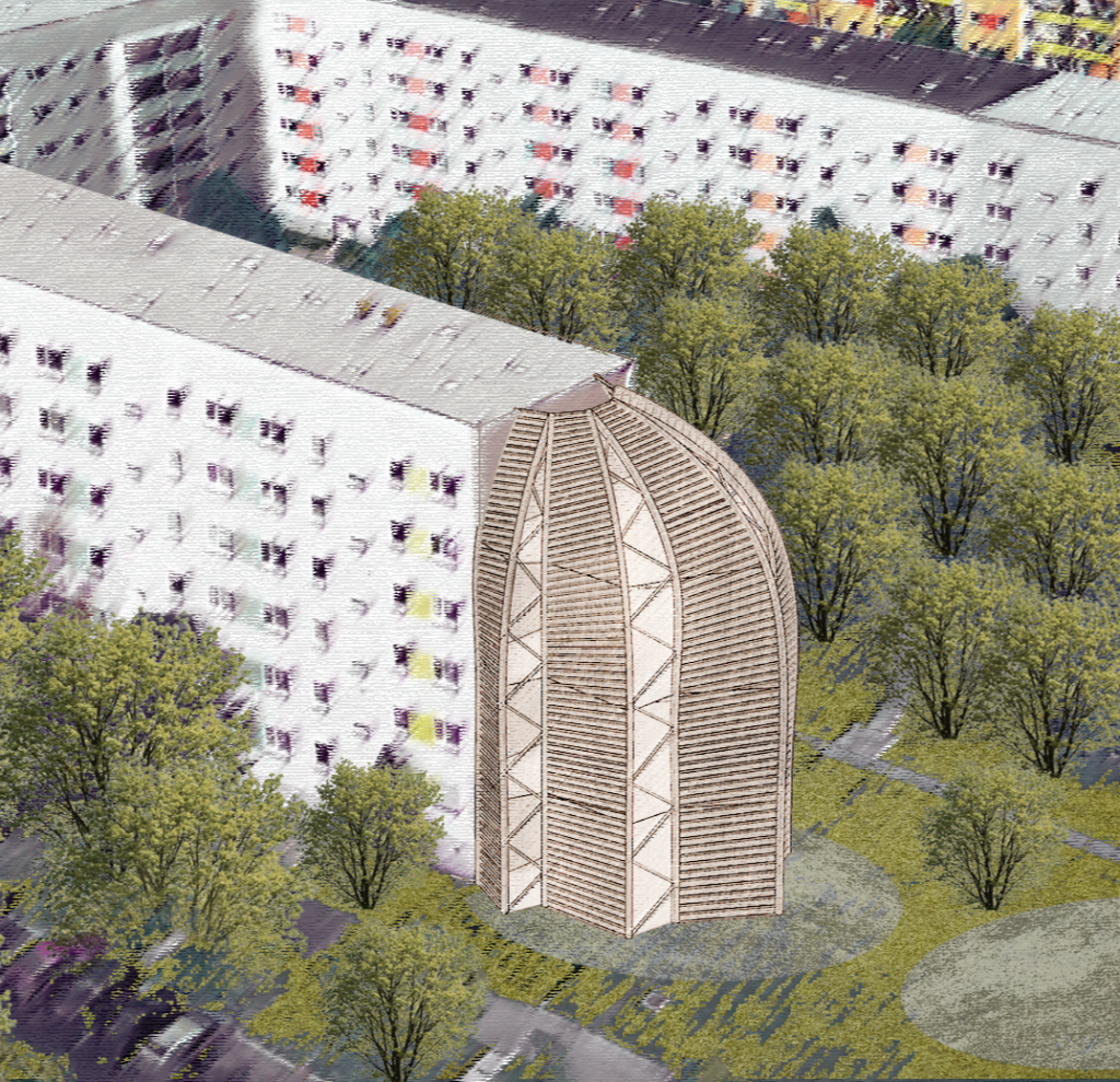
The Timber Ruled Surface system gives designers the ability to generate a structured yet organic form that adapts to the unique social and environmental context of the site. Use cases include multi-use additions to the empty concrete façades of large residential complexes, as well as de-constructable and reusable, free-standing structures. The parametric system is founded on natural and sustainable materials, and a commitment to reusability through repeated elements to be deconstructed, moved, and rebuilt in new locations as needs change.
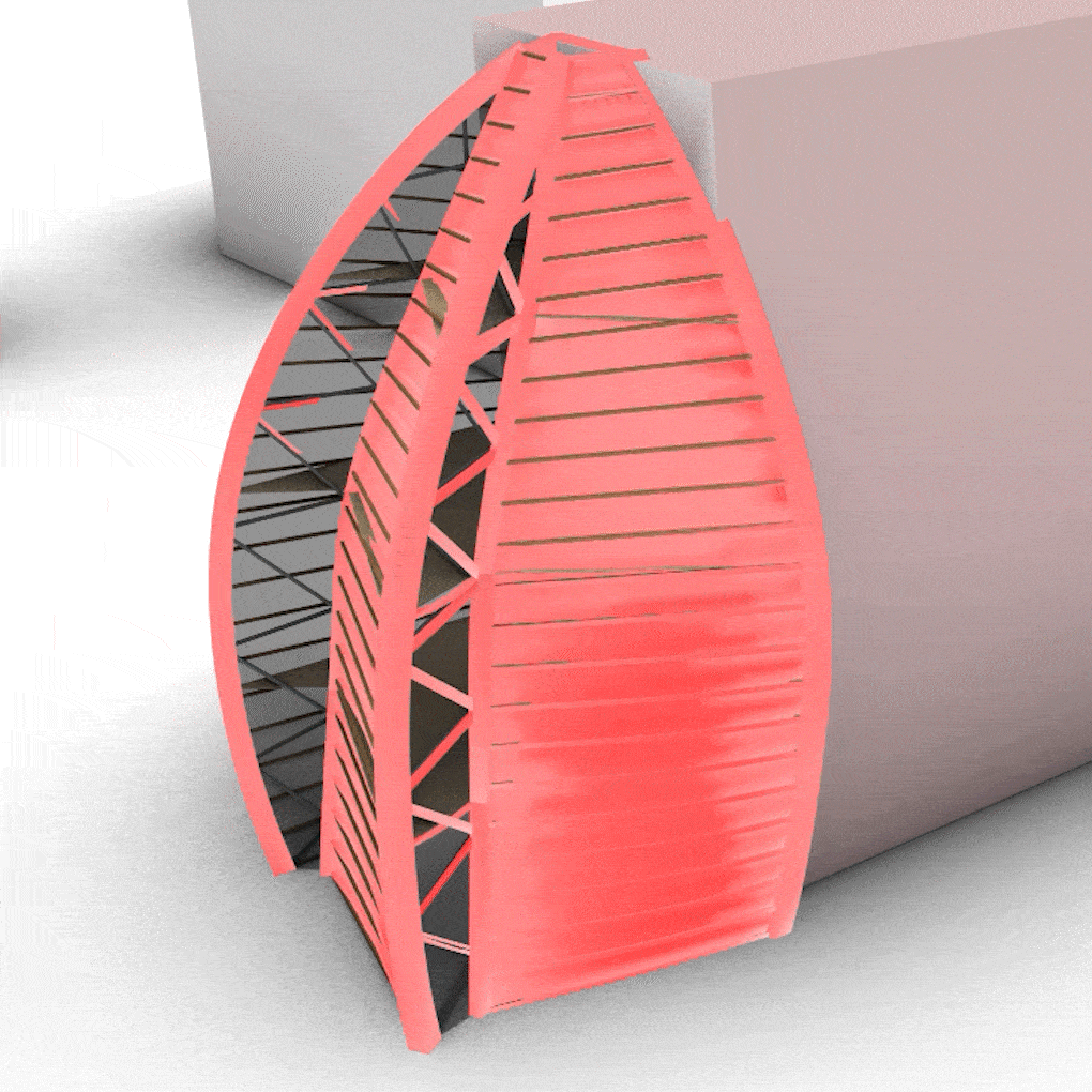
The system itself is defined by a set of glulam arches generated around the perimeter of sets of floors defined by the user. The arches are doubled and offset through a parametric definition to optimize their efficiency under combined gravity and lateral loads, each set forming a truss. Adjacent arches are then interconnected by a series of LVL joists defined by a maximum production length. The joists form a ruled surface to support an outer plywood shell and vegetated wall, with light entering through the trusses.
Context
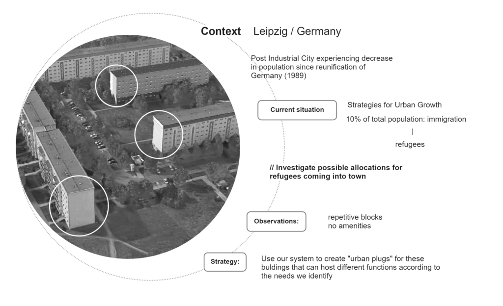
Located in Leipzig, Germany, these common single-use apartment buildings are welcoming new immigrants and refugees. These outdated buildings present an opportunity to provide these residents with additional community spaces that provide multiple services that they lack in the immediate area. The Timber Ruled Surfaces can act as urban plugs on these empty facades, to provide residents with the amenities they are lacking, such as: local food sources through vertical gardens & greenhouses, language learning centers, daycares for children, co-working spaces, etc.
Structural Process
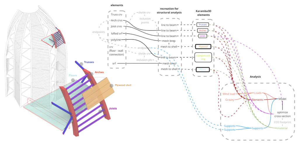
After initial forms are defined based on the input façades on the site, each component of the model must be translated into finite elements using Karamba3D in order to prepare for an optimization process. In the illustration above, they key elements are highlighted; lines and meshes for specific materials are converted into arches, joists, trusses, plywood, and floors. To ensure proper connections between members, divisions were created and added to meshing components as inclusion points and arches were divided at every truss, joist, and floor intersection before being reconstructed as polylines.
?Because initial models were single-story iterations, the addition of floors for multiple program uses required additional material to account for structural displacement. Glulam floor beams, spanning from the wall to the timber arches were included to support the CLT floor plates.
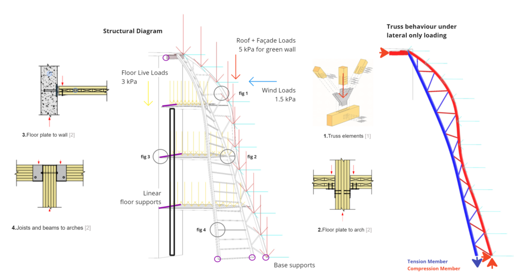
The diagrams above highlights the load paths generated by lateral wind loads, vertical soil loads from green walls, and live loads applied at each floor. The outer surface transfers the wind and soil loads to the horizontal joists and into the arch-trusses. These arches are restrained against vertical and horizontal movement as wall as torsion at the base and peak. The floors introduce additional vertical loads to the arches and are linearly supported by the existing concrete wall at the back. Where concrete walls need additional capacity, vertical columns can support the floor beams, which also help transfer the loads to the arches. On the right, the truss action is shown under lateral loading only, while gravity loads introduce compression forces into both arches.
Structural Exploration
In addition to the preparation of the structural model, several steps of exploration were taken in an attempt to understand some limitations before running an optimization; with an understanding of these limitations, more suitable inputs and ranges can be used when optimizing for a final form.
While giving certain freedoms to the user, constructability and fabrication restrictions are set in these explorations. First, the radius of curvature for the glulam members is limited to 2.2m. Second, the max span of LVL joists, the max distance between these joists that create the ruled surfaces, as well as their range of cross sections were limited through production length and plywood panel limits. Notably, there should be a limit of 10m joist spans and a maximum of ~0.6m between each joist. Next, rotation of the outer glulam arches was manipulated. The model quickly revealed that anything over 20 degrees would cause too much torsion in the trusses. Finally, the number of truss diagonals populating the arches range between 9 and 19 as a result of multiple iterations.
Wallacei X Optimization
Understanding the material limitations and function requirements for the spaces, the model is now ready to go through an optimization process within Grasshopper3D using the Wallacei X evolutionary engine.
Using the Wallacei X component, the optimization process is able to use multiple variables (offset & rotation of outer arches, truss count, joist span, & joist spacing) to solve for multiple goals (minimize material displacement and mass while maintaining a target floor area. After running 500 iterations, the last 50 were further analyzed.
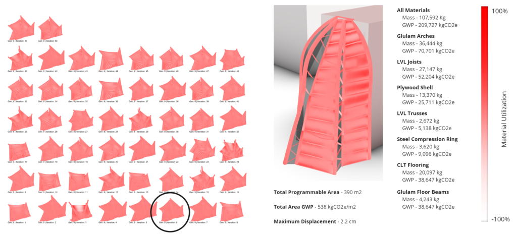
The list of generated solutions was sorted by both displacement and mass before considering aesthetic qualities. After further inspection, option 6 was determined to have the best combination of efficiency and aesthetic qualities. The limitations discovered during the structural exploration phase were essential to producing an optimization process that would produce viable results. Even though all members and materials were accounted for and optimized, it seemed the maximum displacement of 2.2 cm was driven mainly from the CLT flooring. In future rounds of optimization, these floors will need to be analyzed even further before additional optimization can reduce increase the efficiency of the floors.
When looking at GWP of the structure, total emissions per square meter are just over 530 kg of CO2, which is in the typical range of emissions of a commercial use. While we are hoping to show greater efficiency, the additional loads included in the simulation to account for greenwall weight may be driving higher structural requirements. Additional investigations into the structural system should highlight strategies for reducing the building’s embodied carbon.
