Abstract
The aim of this exercise is the understanding of new production techniques through the relation between computer data and machine-oriented fabrication, bringing in a new perspective towards architecture and digital fabrication. As well as being able to invent strategies to translate geometry and systems into articulated and constructible solutions through exploring the opportunities arising from three digital fabrication processes: CNC Milling, Laser Cutting and 3D Printing.
CNC Milling
- Modeling: Rhino + Grasshopper
- CNC Machine: ShopBot
- Materials: Plywood 30 mm
- Post Processor: SBP
- Workpiece Volume: 380x200x30 mm
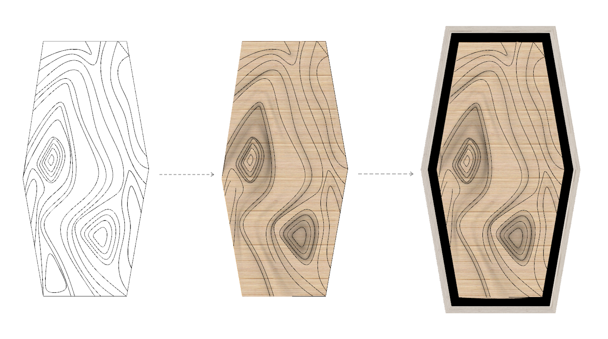
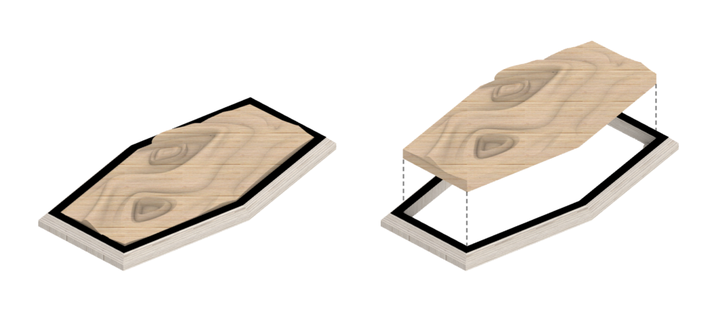
CNC Milling Strategy (Total Mill time: 31 min)
- Step 1: 2 Axis Profiling
- Mill: Flat Mill
- Flute: 2
- Diameter: 6 mm
- Spindle Speed: 12,000
- Cut Direction: Mixed
- Mill Time: 5 mins
- Step 2: Horizontal Roughing
- Mill: Flat Mill
- Flute: 1
- Diameter: 10 mm
- Spindle Speed: 12,000
- Cut Direction: Mixed
- Step Down Control: 50%
- Stepover Distance: 25
- Mill Time: 6.4 mins
- Step 3: Horizontal Roughing
- Mill: Ball Mill
- Flute: 2
- Diameter: 6 mm
- Spindle Speed: 12,000
- Cut Direction: Mixed
- Step Down Control: 25%
- Stepover Distance: 3.175
- Mill Time: 19.4 mins
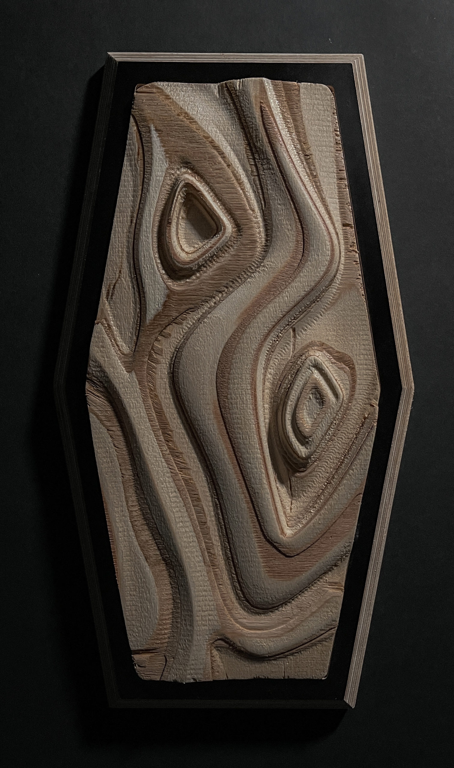
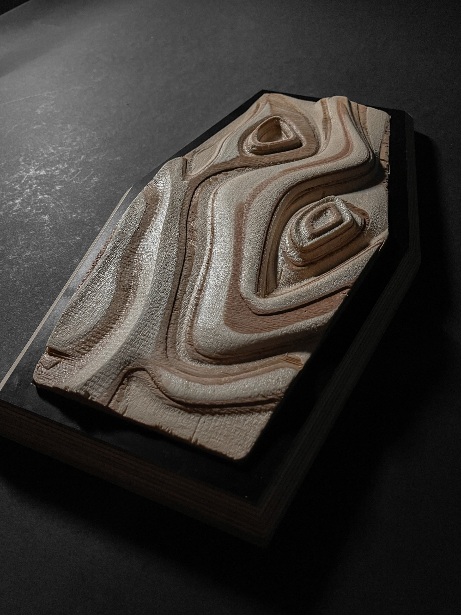
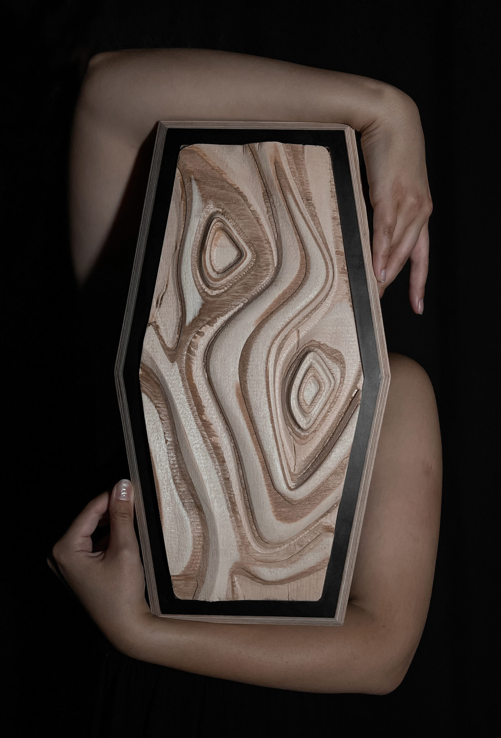
Final Model Photographs
Laser Cutting
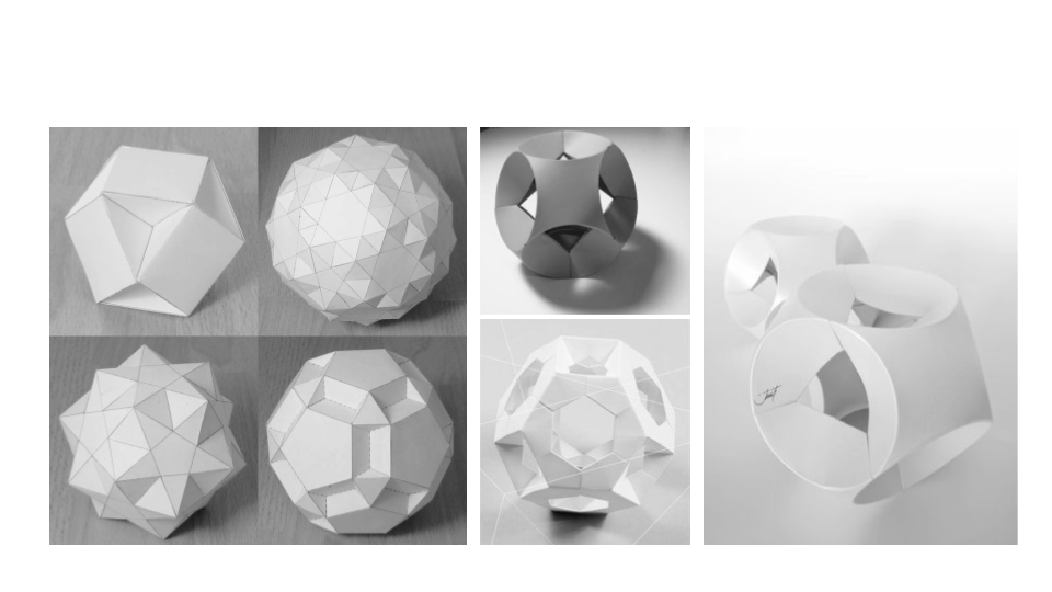
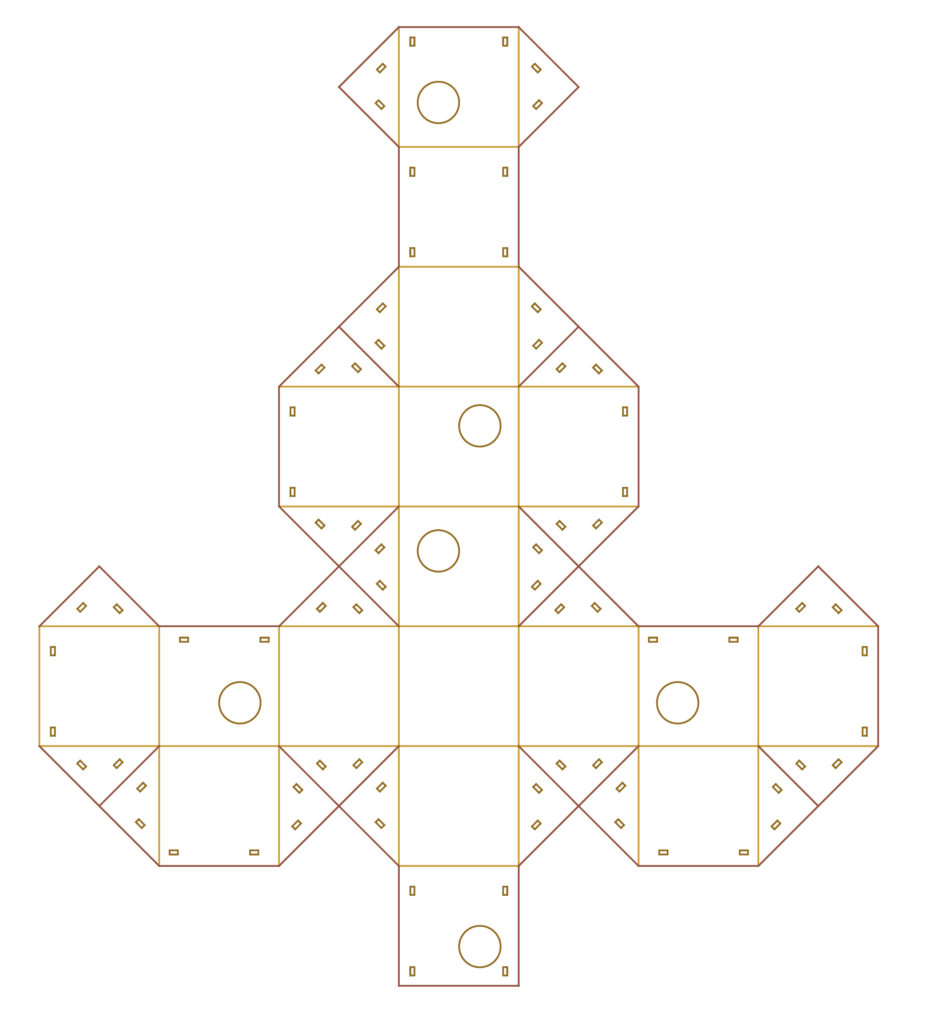
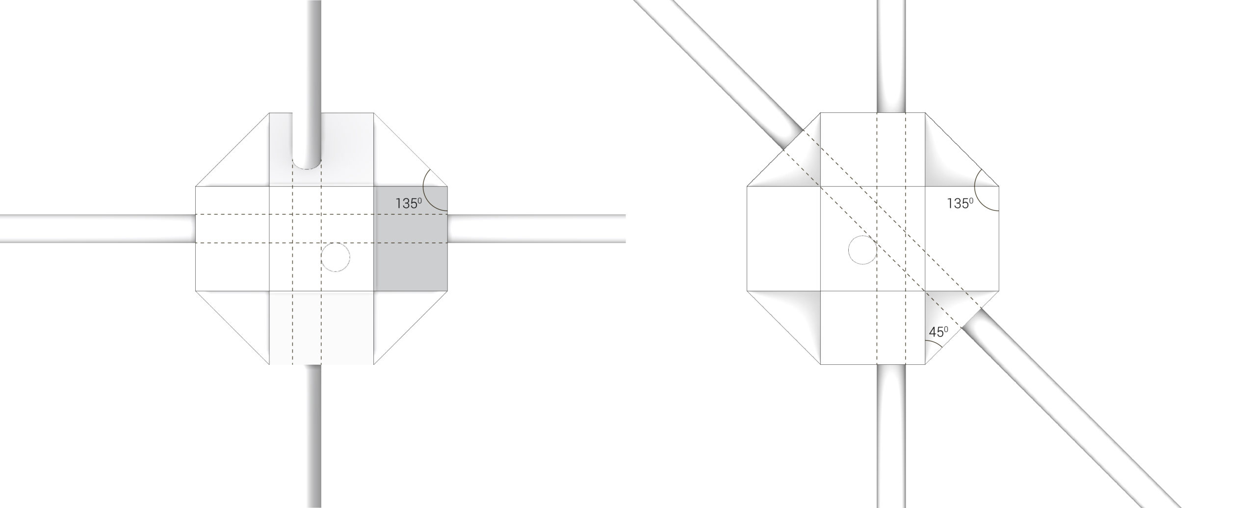
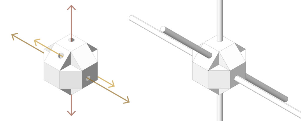
Through laser cutting and folding technique, the aim was to join simple recycled timber beams to form complex spatial structures that follow a constructive assembly logic ruled by spatial joints. By having the main inspiration as origami folds, the module was designed in a matter that would offer multiple directions and angles of connection.
- Modeling: Rhino + Grasshopper
- Machine: R500
- Materials: Cardboard – 5.7mm Double layered
- Joint type: Folding
Laser Cutting Parameters
Cutting time: 6 mins / Module
- Layer 1: Half Cut | Power 25 | Speed 2
- Layer 2: Cut | Power 11 | Speed 2
- Layer 3: Cut | Power 25 | Speed 2
Form / Surface
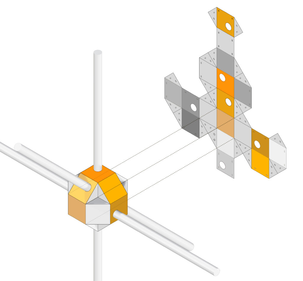
Timber Assembly
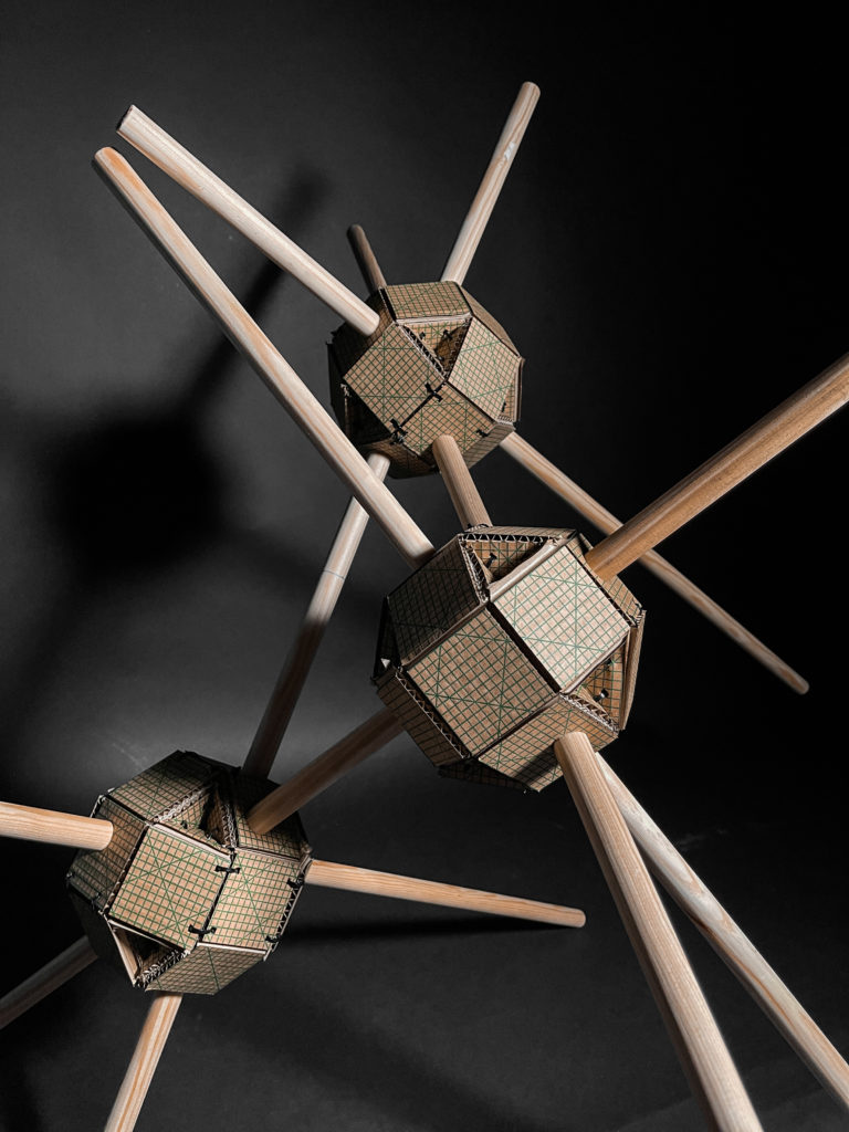
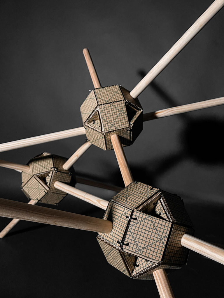
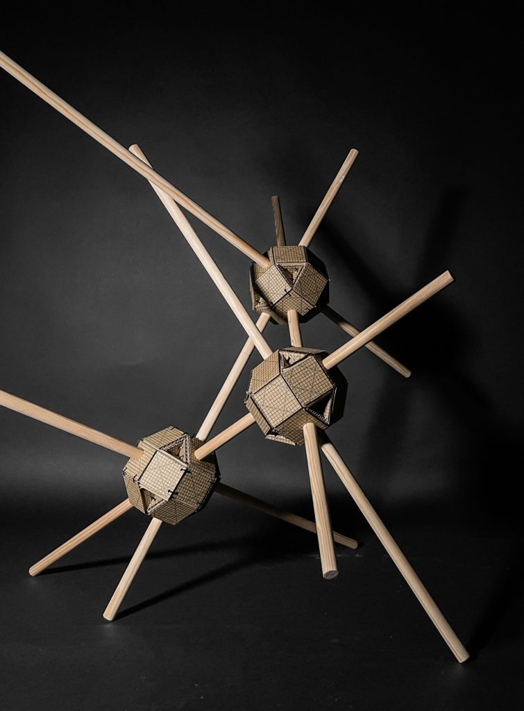
Module Aggregation
Final Model Photographs
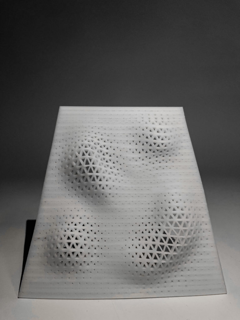
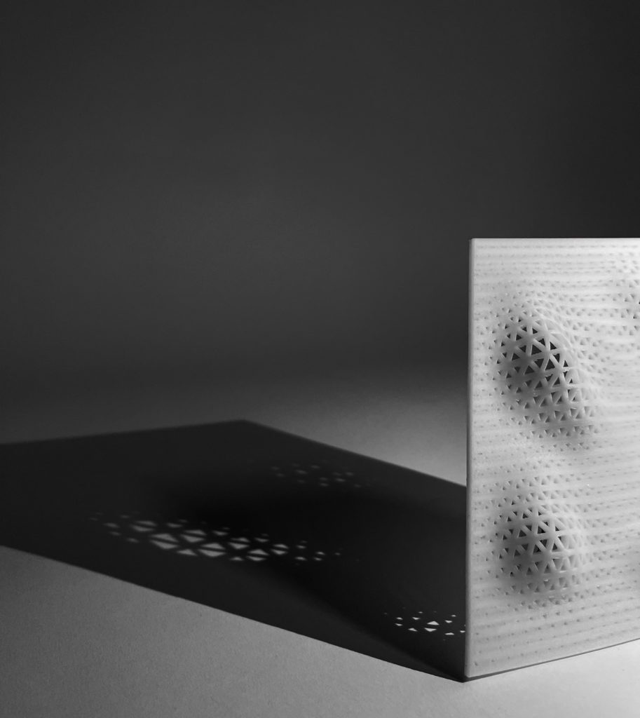
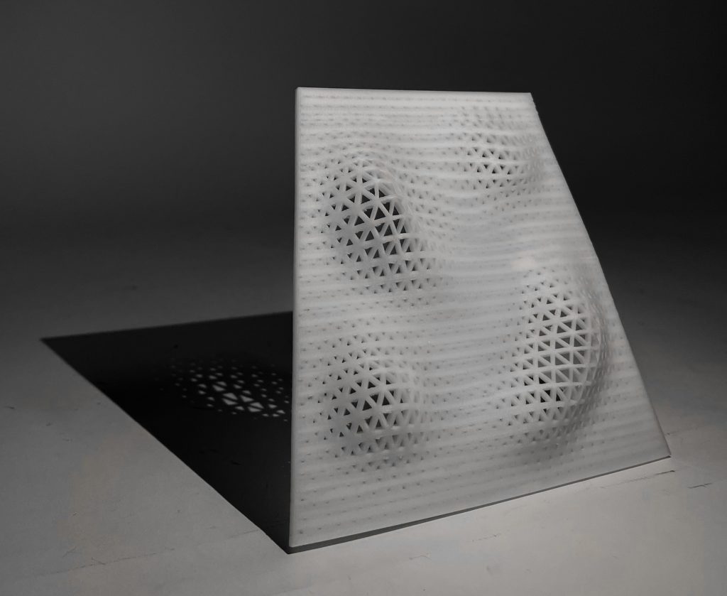
3D PRINTING
The aim of the design is to obtain a minimal surface having its openings’ direction and size controlled by attractor curves in order to optimize the sun and shading usage.
- Modeling: Rhino + Grasshopper
- Materials: ABS
- Machine: Zortrax M200 Plus
Printing Properties
- Printer: Zortax M200
- Material: Z-ABS 2
- Nozzle Diameter: 0.4 mm
- Layer: 0.19 mm
- Infill: 30%
Final Model Photographs