
CONCEPT
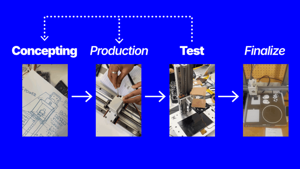
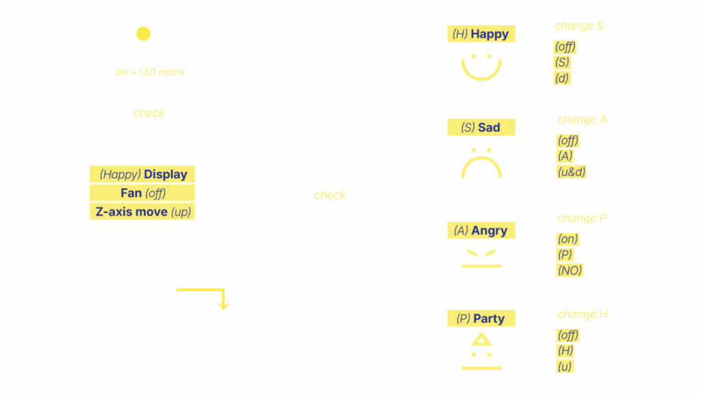
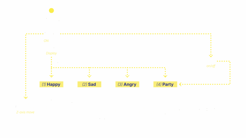
IDEATION FLOW CHART


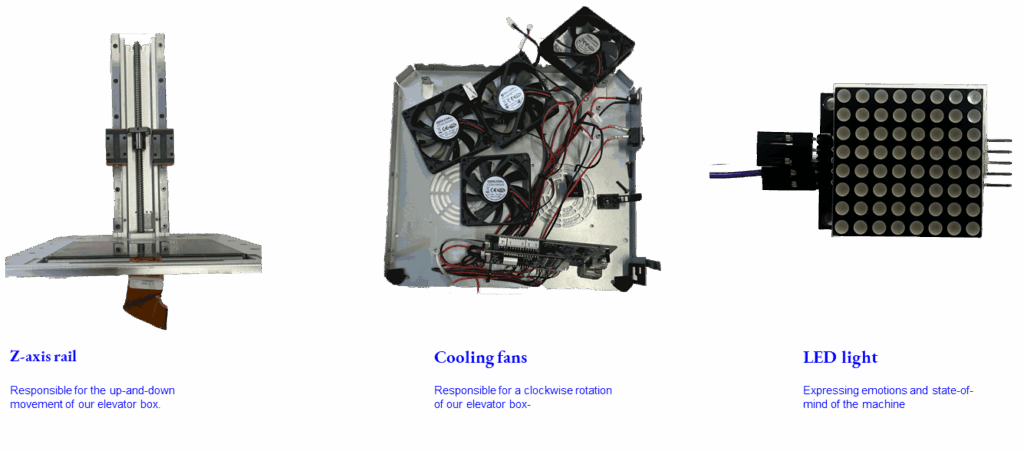
SELECTED COMPONENTS
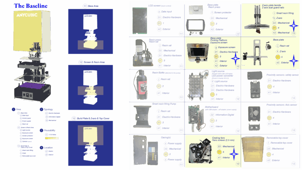
Components
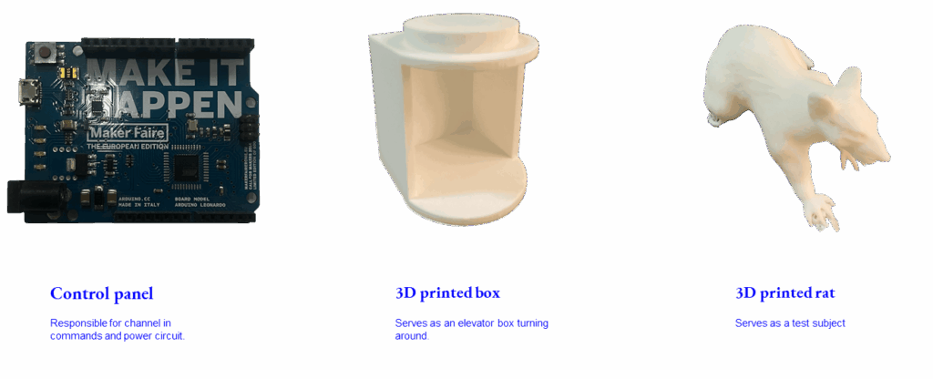
Prototypes
Forensic Report
Agency
Senior Forensic Team
Case identifier
MDEF-MAA-UTS-001
Members
Alejandra Rivera Zamacona, Armin Gulbert, Ludovico Celli, Melissa Ingaruca Moreno, Rishi Srinivasan, Swarna Manjari Chellapandi
Date of Receipt
19 November 2025
Date of Report
21 November 2025
Website URL
https://hackmd.io/@nmoHUr94RLOmMhWqUedElQ/B1AbeLjlbg
Purpose of the Report
The purpose of this document is to provide a comprehensive overview of the forensic / due diligence activities carried out on a malfunctioning electronic device.The report serves as a key deliverable of the team work members did for the “Unpacking Tech Systems” course within the MDEF program at IAAC.
Structure of the Report
The report was built based on the following structure:
- Scope of the report:
- Describing the analyzed machine
- Description of the forensic activities performed
- Background and Context:
- Purpose of the system
- High-level functionality
- Circumstances in which we found the machine
- How is it built?
- Overview on general build
- Functionality system map
- Listing components
- Health check of the system:
- Procedures and results
- Categorization of components
- Defined critical questions and observations
Scope of the report
Anycubic Photon M3 Plus
Product Name
3D Printer
Model
Anycubic Photon M3 Plus
Weight
12 kg
Machine Size
360*290*475 mm
Printer Serial Number
ML2207B0400814
Firmware
Anycubic Photon M3 Plus upgrade V2.1.0.3 firmware EN
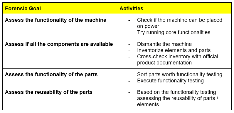
Forensic activities
This section gives a brief overview of the forensic goals and linked activities.
Background & Context
Purpose of the System
The selected machine is an Anycubic 3D printer using resin-based technology for creating 3D objects. The machine serves its users to turn the 3D design into tangible objects.
Functionality
This section gives a brief overview of the key functionalities of the printer to have a general understanding on the user experience, procedures and dependencies with other machines, systems.
The chart below contains a high-level system map covering a context-base visualization of the main process steps and information/material flows:

Based on the chart the following key functionalities have been identified:
Receiving information and files
Processing and de-bundling information and file packages
Communication with other machines / systems using wired and wireless connections
Raw material management
3D object creation using UV technology
Safety and maintenance procedures
Manage cooling
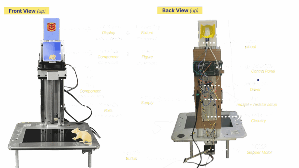
High-level anatomy

Critical questions, observations and assumptions
- Cost of printers vs Cost of components
- Is it better to buy a new one or replace/repair components?
- Was the LCD panel issue the only reason for the decommissioning of the machine?
- The malfunctioning of the LCD panel limits initial functionality testing of the machine
- How can non-functioning elements be reused?
What are the reusable components?
Sources
https://wiki.anycubic.com/en/resin-3d-printer/photon-m3-plusCritical Questions & Assumptions
Component Forensic Report
Purpose of the Report
The purpose of this document is to provide a comprehensive overview of the forensic/due diligence activities carried out on a key component of the Anycubic Photon M3 Plus 3D printer.
Structure of the Report
The report was built based on the following structure:
- Build and Technical overview
- Functionality overview
- Code example resulting functioning component
- Schematic diagrams illustrating component functionality and test scenario
- Utilisation ideas, listing of potential utilisation scenarios
Build and Technical Overview
The component contains mechanical and electronic elements. The Z lead screw, platform bucket and the dual rail are the mechanical elements operated by the electro motor. The motor receives power and instructions via signal from the motherboard. The motor rotates the Z leads screw through steps triggered by signals. Later in this document we describe in detail the code snippet we used to activate the motor and movement.

Functionality Overview and Testing
Within the core functionality of the 3D printer, this component has a key role. Based on the received signals from the mother board – channeling in the printing process, parameters and instruction – the motor starts spinning the Z lead screw. That is responsible for the up-down direction movement of the build plate. This movement ensures that the printing follows a consistent pace and rhythm. In this process the code-based instructions of the Firmware is turned into movement.
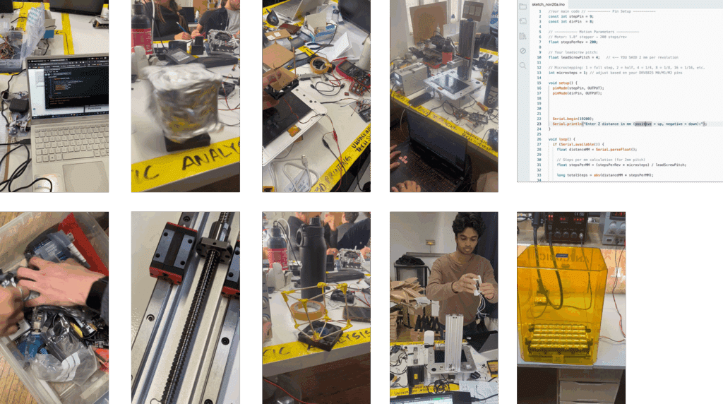
Code examples of functionality
Code: Stepper Motor Rotation
// Define stepper motor connections and steps per revolution:
#define dirPin 8
#define stepPin 9
#define stepsPerRevolution 200
void setup() {
// Declare pins as output:
pinMode(stepPin, OUTPUT);
pinMode(dirPin, OUTPUT);
}
void loop() {
// Set the spinning direction clockwise:
digitalWrite(dirPin, HIGH);
for (int i = 0; i < stepsPerRevolution; i++) {
// These four lines result in 1 step:
digitalWrite(stepPin, HIGH);
delayMicroseconds(2000);
digitalWrite(stepPin, LOW);
delayMicroseconds(2000);
}
delay(1000);
// Set the spinning direction counterclockwise:
digitalWrite(dirPin, LOW);
for (int i = 0; i < stepsPerRevolution; i++) {
// These four lines result in 1 step:
digitalWrite(stepPin, HIGH);
delayMicroseconds(1000);
digitalWrite(stepPin, LOW);
delayMicroseconds(1000);
}
}
Code: Stepper Motor Movement Based on user input distance
// ———– Pin Setup ———–
const int stepPin = 9;
const int dirPin = 8;
// ———– Motion Parameters ———–
// Motor: 1.8° stepper → 200 steps/rev
float stepsPerRev = 200;
// Your leadscrew pitch:
float leadScrewPitch = 4;
// Microstepping: 1 = full step, 2 = half, 4 = 1/4, 8 = 1/8, 16 = 1/16, etc.
int microsteps = 1; // adjust based on your DRV8825 M0/M1/M2 pins
void setup() {
pinMode(stepPin, OUTPUT);
pinMode(dirPin, OUTPUT);
Serial.begin(19200);
Serial.println(“Enter Z distance in mm (positive = up, negative = down):”);
}
void loop() {
if (Serial.available()) {
float distanceMM = Serial.parseFloat();
// Steps per mm calculation (for 2mm pitch)
float stepsPerMM = (stepsPerRev * microsteps) / leadScrewPitch;
long totalSteps = abs(distanceMM * stepsPerMM);
// Direction
if (distanceMM > 0)
digitalWrite(dirPin, HIGH); // UP
else
digitalWrite(dirPin, LOW); // DOWN
Serial.print(“Moving “);
Serial.print(distanceMM);
Serial.println(” mm”);
// Step loop
for (long i = 0; i < totalSteps; i++) {
digitalWrite(stepPin, HIGH);
delayMicroseconds(600);
digitalWrite(stepPin, LOW);
delayMicroseconds(600);
}
Serial.println(“Done. Enter next distance:”);
}
}
