
The project documents the iterative design and manual fabrication of a 3-meter span beam constructed exclusively from limited recycled wooden members.
Iterations
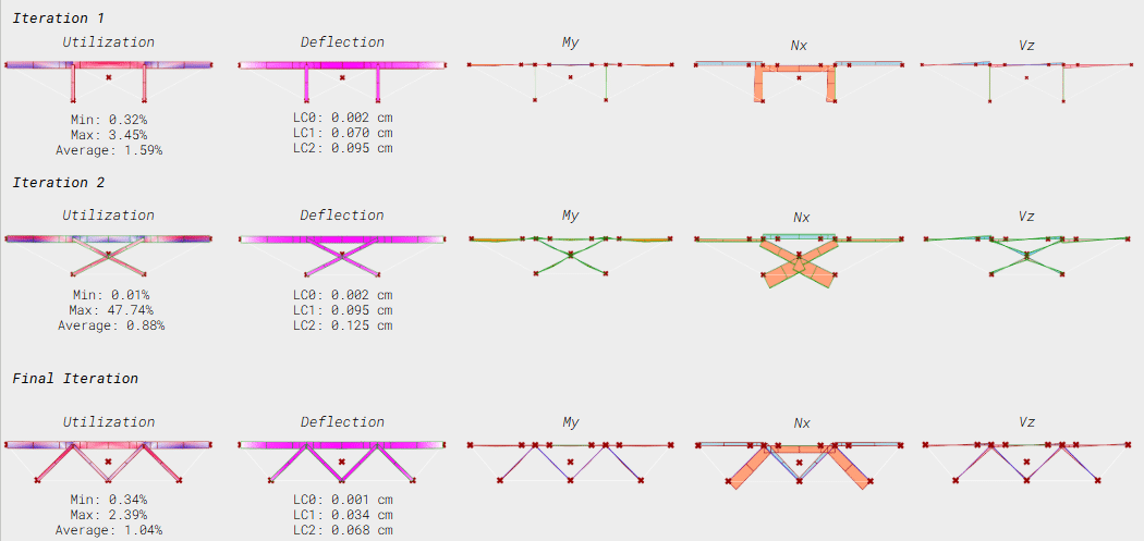
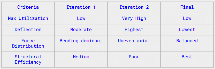
The beam was developed through a series of structural iterations evaluated using utilization ratio, deflection, bending moment, axial force, and shear force. With a fixed inventory of recycled wooden elements, optimization focused on reorganizing the same members rather than adding material.
FINAL EVALUATION
The initial bending-dominant system evolved into an axially engaged configuration through diagonal integration. The final triangulated arrangement maximized stiffness, reduced bending demand, and achieved improved structural efficiency within material constraints. Compared to the initial vertical support system and the cross-braced alternative, the final iteration achieves improved stiffness and structural efficiency through balanced axial and bending force interaction.
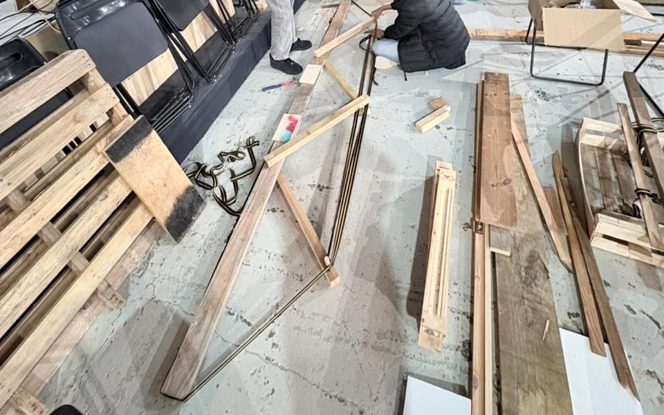
Waste as Structure
After resolving the structural system through iterative analysis, we shifted from simulation to inventory where we worked exclusively with wooden elements collected from a pile of discarded and previously used materials(Recycled wood).

FINAL BEAM DESIGN
Following structural iteration and material cataloguing, the finalized configuration was developed into a detailed digital model. Member dimensions and connection details were aligned with the available reclaimed timber elements. This model served as the basis for precise manual fabrication of the 3-meter beam.


The finalized digital model was translated into physical assembly using the reclaimed timber members and resolved joint details. Precision in cutting, alignment, and fastening ensured structural integrity across the 3-meter span prior to load testing.
POINT LOAD TEST
The fabricated beam was subjected to incremental loading to evaluate structural performance under controlled conditions. Maximum recorded deflection reached 1.2 cm at an applied load of 670 kg, marking the onset of structural failure.
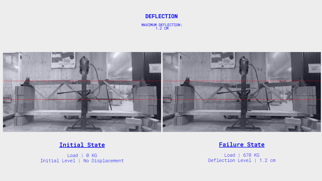
Failure was initiated by excessive mid-span deflection, leading to instability within the triangulated system and localized overstressing at critical connection points. The test highlighted the governing role of joint behavior and compression member

Load–Deflection Performance Curve

The load–deflection graph illustrates the progressive displacement response of the beam under incremental loading. A near-linear relationship was observed up to higher load levels, indicating predominantly elastic behavior within the structural system.
Maximum recorded displacement reached 1.2 cm at 0.67 kN (670 kg), corresponding to the ultimate load capacity. The curve confirms stiffness characteristics of the triangulated configuration and identifies the threshold at which structural instability initiated.

JOINT FALIURE
Failure originated at the top chord connection due to localized bearing stress and fastener pull-out under combined compression and shear.
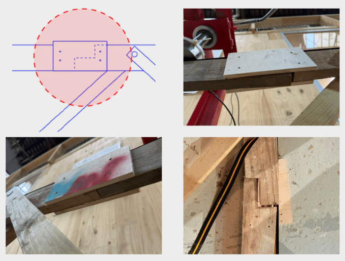
During the beam test, the load was gradually increased. At about 0.43 kN, one of the joints began to fail. Loading continued up to 0.67 kN, during which cracking sounds were heard and the beam showed significant deflection at midspan.
WHY DID THIS HAPPEN?
The main reason for the joint failure was insufficient fastener strength at the connection. There was insufficient connection capacity under combined shear and eccentric axial loading. The screws could not resist the combined shear and pulling forces, leading to pull-out and separation of the joint.
