
TerraPilot: A Site-Aware AI Co-Pilot for Early-Stage Architectural Massing
TerraPilot is a working prototype for early-stage architectural massing. It connects natural-language prompts, real site data, editable geometry, and score-based feedback within one design workflow. The project does not present itself as a final simulation platform or construction-documentation system. Instead, it explores how an AI agent can support architects during the early stages of site-aware design exploration.
From Prompt to Site-Fitted Massing
The Design Problem
Early-stage architectural design often requires rapid testing of building massing options while responding to site conditions such as roads, sun, wind, surrounding buildings, access, and amenities. These investigations typically involve several tools and manual translation between design intention, site data, geometry, and performance feedback.
TerraPilot addresses this gap by allowing the designer to use plain-language prompts such as “add three floors,” “open toward the park,” or “align to the road.” The system interprets these requests, connects them to site context, and updates massing geometry while reporting design-health scores and trade-offs.
What TerraPilot Attempts to Do
The project goal is to turn a plain-language design brief into validated, site-fitted building massing. This means that the system is not only generating form, but also checking whether the generated geometry fits the site, responds to contextual information, and can be edited or compared through the interface.

System Logic: An Agent That Reasons, Acts, and Validates
The ReAct Loop
The agent is structured around a reactive reasoning loop. This loop through the sequence: reason, act, observe, validate, debug, retry, pass, and implement. This structure is important because the agent is not treated as a one-shot text generator. It is expected to test its actions against the design task and site constraints before implementation.
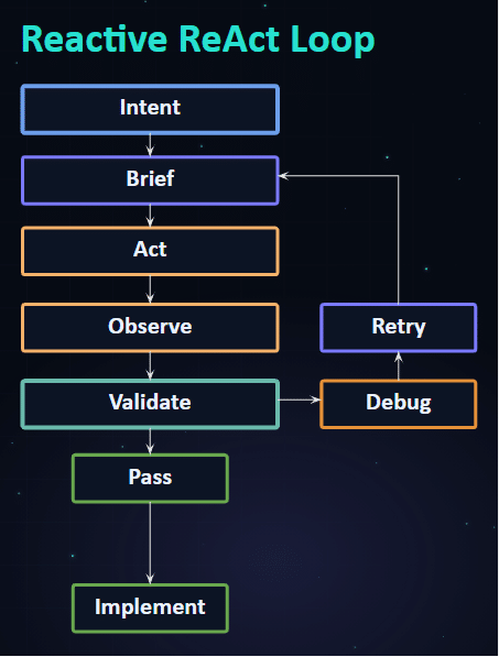
The agent follows a reactive loop: reasoning, acting, observing, validating, debugging, retrying, and implementing.

The Agent State Graph
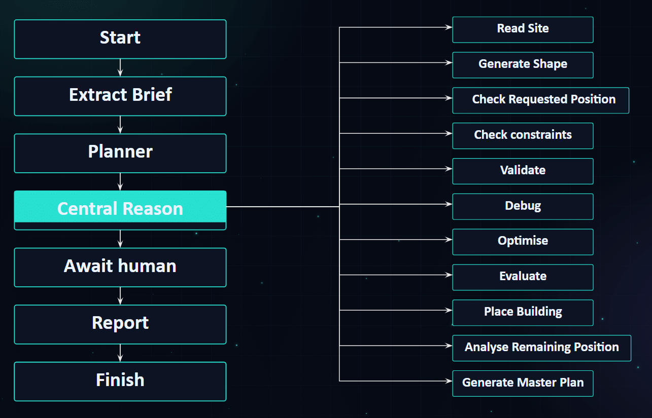
The agent workflow is implemented as a state graph. The main sequence begins with start, brief extraction, planning, central reasoning, human confirmation, reporting, and finish. From the central reasoning node, the system can call specific operations such as reading the site, generating a shape, checking requested position, checking constraints, validating, debugging, optimizing, evaluating, placing the building, analyzing remaining position, and generating a master plan.
Validation Through Self-Debugging
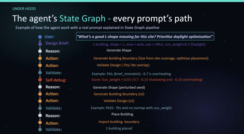
A user asks the agent to find a good L-shaped massing for the site while prioritising daylight optimisation. The agent extracts the design brief as one L-shaped office building, automatically determines the appropriate building area from the site, and assigns a daylight weighting of 0.7. It generates an initial building boundary and validates the design, but the proposal fails because the daylight priority causes overheating. The agent then self-debugs by lowering the daylight weighting to 0.55, regenerates the shape using a perturbed seed, and validates the design again. Once the proposal satisfies the site constraints with no overlap and balanced daylight performance, the building is placed and the final boundary is imported into the site.
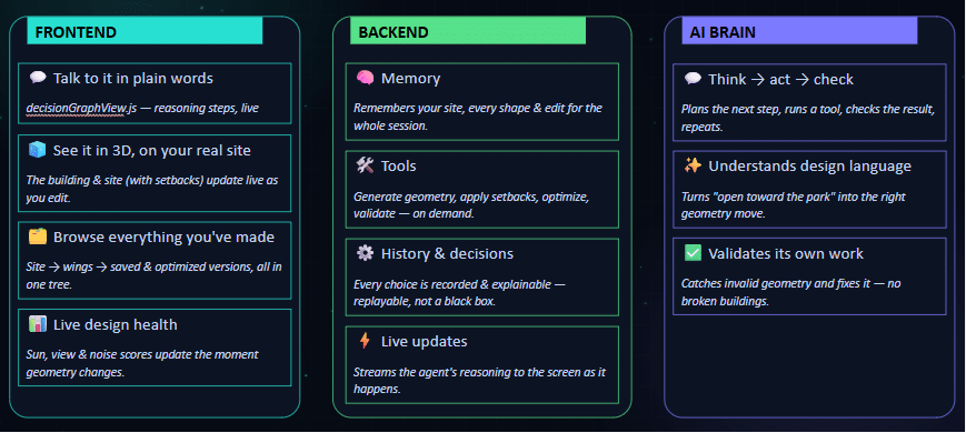
Frontend, Backend, and Agent Architecture
Frontend Interface
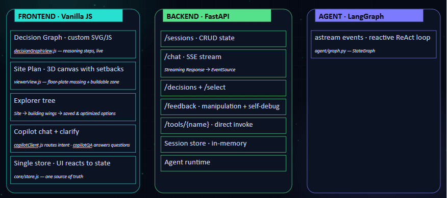
The frontend is built around a React interface. Several interface components: a decision graph using React Flow, a site plan canvas with setbacks, an agent activity trace, an explorer tree, a chat strip, and a clarification panel. These components organize the interaction between designer, site data, generated options, and agent reasoning.
Backend Routes and Session Logic
The backend is organized around session-based routes. This lists routes for CRUD session state, chat streaming through SSE, design decision and selection, clarification, and direct tool invocation. The session store is described as in-memory, which is important to treat as a prototype-level implementation rather than a production persistence model.
Agent Runtime and Tool Layer
The agent layer is described through LangGraph, a reactive ReAct loop, an OpenAI decision engine, and local Python tools with MCP. This architecture allows the agent to interpret prompts, call tools, validate outputs, and return updates to the interface.
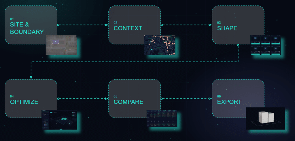
The Guided Design Workflow
The interface is structured as a guided workflow with six major stages: site and boundary, context, shape, optimize, compare, and export. This sequence gives the prototype a clear design logic: first locate and define the site, then build contextual awareness, then generate and manipulate massing, then evaluate and compare alternatives before export.
Site and Boundary
The workflow begins with site setup. The user enters a site prompt or location, the system geocodes it using OpenStreetMap, the user drops a pin, activates the drawing tool, draws the site boundary, and saves the site. Once the site is saved, location information is stored in the site explorer.
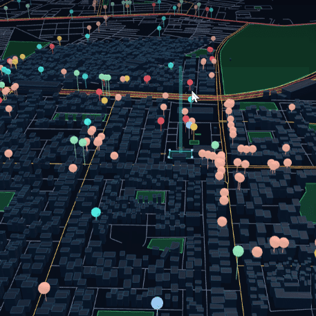
Context Analysis
After the boundary is confirmed, TerraPilot starts context analysis. The system builds a 2 km query, fetches OpenStreetMap data, analyzes and stores context data, and classifies features into explorer layers. The project uses this contextual layer structure to inform later geometry generation and scoring.
Shape Generation
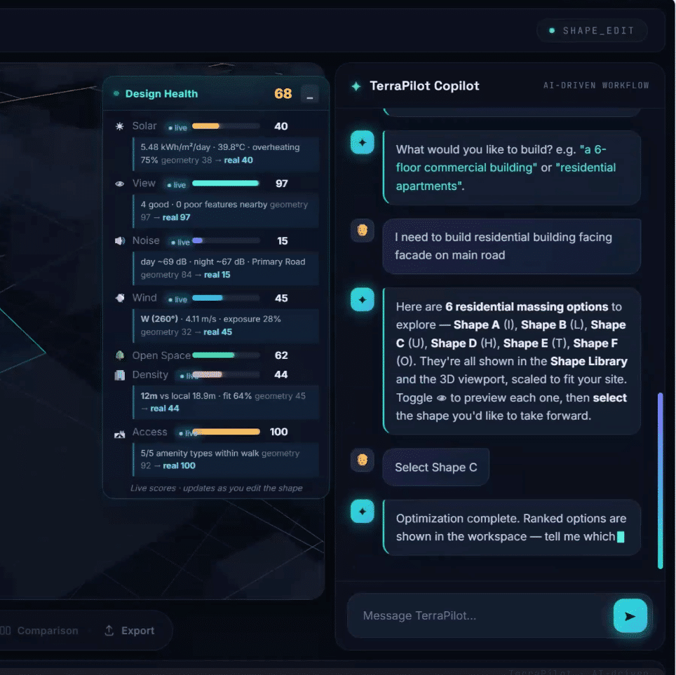
Shape generation starts from the recorded context features and the user prompt. The system interprets design intent, generates multiple building typologies, evaluates site fit, ranks the options, and displays a shape library. The user then selects and confirms a preferred shape, which is output to the 3D viewer.
Prompt Interpretation
The first layer handles direct commands, such as a request for a U-shaped residential building. The second layer handles semantic intent, where the user may describe design intentions without naming a specific typology. The third layer is a reasoning node, used when the request requires additional interpretation before geometry can be generated.
For example, a request for a residential building with a central courtyard, a long facade facing the main road, and two wings on either side is treated as a more complex prompt that requires reasoning before it can be translated into a massing operation.
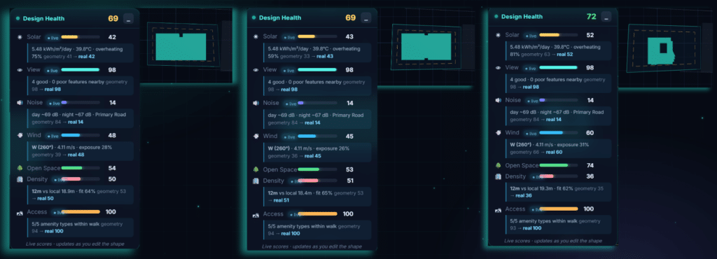
Live Design Health
The live dashboard evaluates design performance when the geometry changes. We identifies NASA POWER as a source for wind, solar, and temperature data, and OpenStreetMap as a source for roads, noise, amenities, and buildings. The live design-health panel reports metrics including solar, view, noise, wind, open space, density, and access.
This dashboard should be understood as score-based guidance rather than validated physical simulation. The project explicitly states that current scoring is not a CFD, Radiance, or acoustics solver.
Manipulation
After a shape is generated, the user can give design feedback. The system interprets the feedback, understands the design request, applies geometry transformations, validates the updated building design, saves the updated geometry, refreshes the 3D model, and updates the live design-health dashboard.
Optimization
The optimization workflow begins when the user selects one or more shapes to optimize. The system starts optimization, generates multiple design variants, evaluates them through multi-objective performance criteria, ranks and selects the best variants, stores the optimization results, updates the 3D building, and displays the results in the optimization explorer.
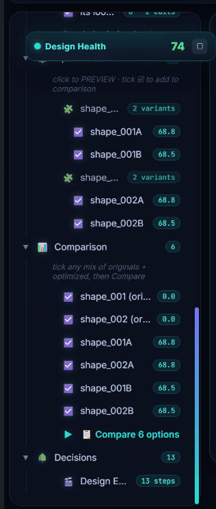
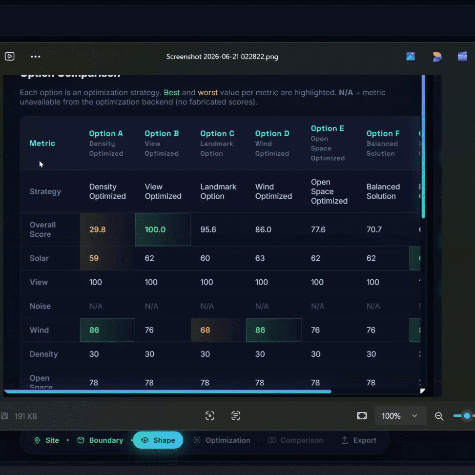
Comparison
The comparison workflow allows users to select design alternatives, retrieve optimization results, build a performance comparison, rank design metrics, display a comparison table, and compare design performance. This step supports traceable decision-making by placing alternatives and metrics into a shared view.
Export
The export workflow describes final design selection, saving selected alternatives, choosing an export format, generating the export file, downloading the design file, and recording the design decision. However, the limitations slide states that the current export is GeoJSON only and that native Rhino, Revit, and IFC integration remains future work.
Results Demonstrated in the Prototype
TerraPilot as a working prototype with a dashboard, site setup, context ingestion, prompt-based shape generation, live design-health scoring, geometry manipulation, optimization, comparison, and export workflow. The system’s strongest demonstrated result is the agent validation example for a 1200 m² L-shaped building, where the agent identifies an area mismatch, adjusts the geometry, validates the corrected result, and places the building once it fits the site with no overlap.
The interface also demonstrates a clear separation between project explorer, 3D viewport, prompt history, prompt input, and workflow stages. This organization supports the project’s central claim: that an architectural massing workflow can become conversational while remaining connected to site data and design feedback.
Current Limitations
The project clearly distinguishes between score-based guidance and real simulation. The current system provides fast feedback, but it is not a CFD, Radiance, or acoustics solver. This distinction is important because the dashboard metrics should not be presented as physically validated simulation results.
The LLM is running on a free-tier quota, which means fallback keyword logic may be needed and nuanced intent can drop. Export is currently GeoJSON only, with no native Rhino, Revit, or IFC bridge. The system is limited to a single conceptual building and is not intended for construction documentation. Context data is limited to OpenStreetMap, and sparse areas may produce N/A scores.
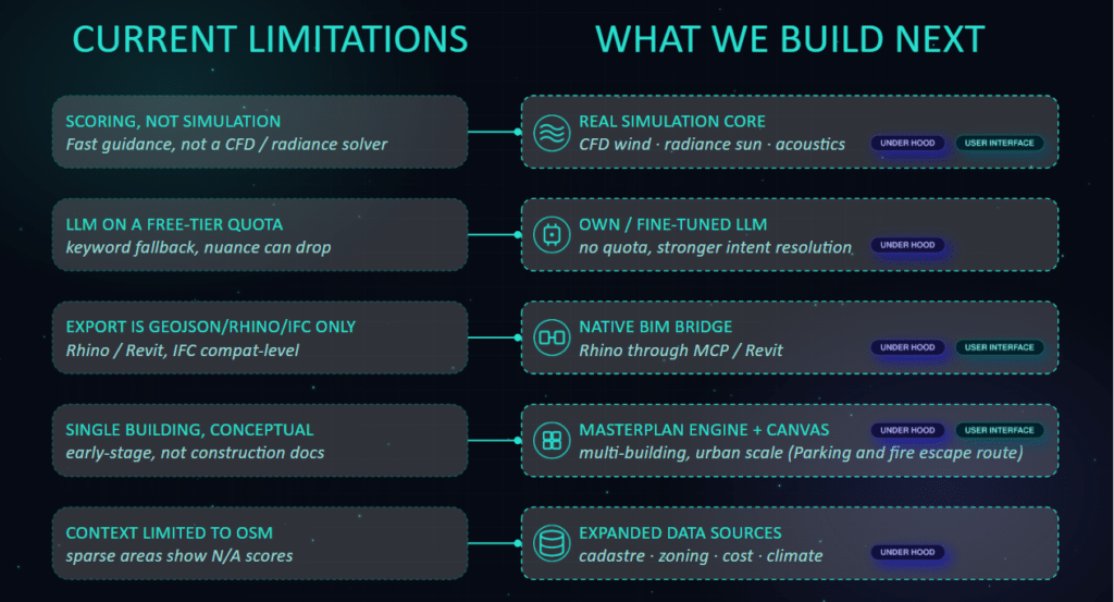
The future development roadmap includes a real simulation core for CFD wind, Radiance sun analysis, and acoustics; an owned or fine-tuned LLM for stronger intent resolution; a native BIM bridge for Rhino, Revit, and IFC workflows; a masterplan engine for multi-building urban-scale work; and expanded data sources including cadastre, zoning, cost, and climate data.
These additions would move TerraPilot from a conceptual massing assistant toward a more robust computational design platform. However, they should be framed as future work rather than current functionality.
DEMO

Reflection
TerraPilot is strongest when presented as a prototype for traceable, AI-assisted massing exploration. Its main contribution is not the automation of architectural design, but the structuring of a workflow where natural-language intent, site context, editable geometry, and score feedback are connected through an agentic system.
The project is technically promising because it exposes the agent’s reasoning structure, validates geometry, supports iterative edits, and allows alternatives to be optimized and compared. Its current limitations are also significant: the scoring is not simulation, export capability is limited, and the prototype remains focused on single-building conceptual design. For an academic blog, the most accurate framing is therefore: TerraPilot demonstrates a working pipeline for site-aware AI massing, while also identifying the technical steps needed before it can become a validated simulation or BIM-integrated design platform.
