
The reference marking system for Additive Manufacturing
Context
Additive manufacturing (AM) technologies have established and grown significantly over the past few decades, solidifying themselves as a mature and competitive alternative across various sectors of fabrication and construction. This development has been observed across multiple levels and applications of production, primarily due to its remarkable properties of flexibility, customization and adaptability on demand.
Working with a diverse range of applications and material requirements in numerous markets, additive manufacturing has proven its worth in meeting local needs effectively.
With a projected annual growth rate of over 20%, additive manufacturing is set to double the global market value (surpassing USD 35 billion) within the next five years. This remarkable expansion is pushing the boundaries of fabrication and technology in many fields, extending from domestic desktop 3D printers to construction site AM infrastructures.
Framework
This research aims to find these boundaries on AM, exploring projects that tackle known or potentially known physical references to adapt to generate complex geometries to print on 3 different levels:
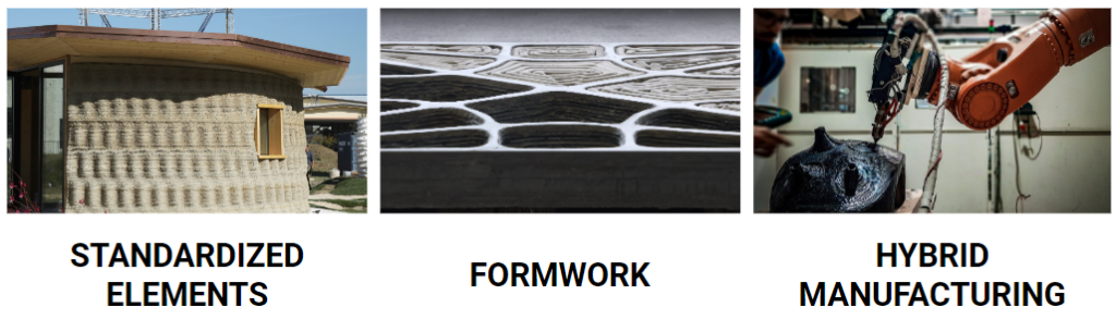
Any of these fields require a precise reference of certain elements involved during or/and after the process of printing.
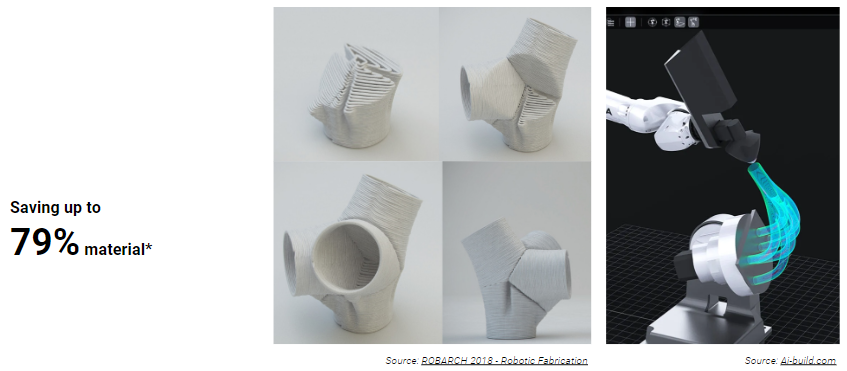
Without doubt, robotic or 6-axis tools have proven to approach more efficiently on certain works, even avoiding the use of extra material on non planar or conformal toolpath printings.
Nevertheless, despite the level of technology used, additive manufacturing still finds a significant challenge in aligning physical references with the digital environment that the printing model needs to take into account.
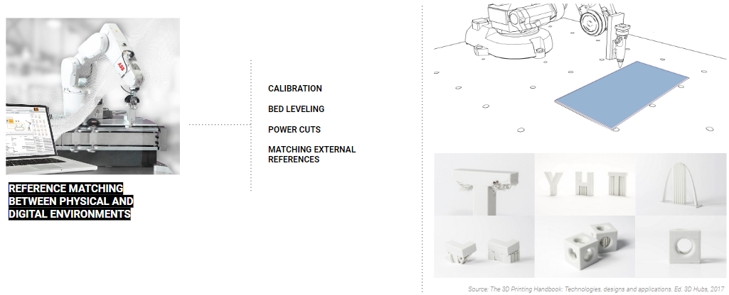
There are many situations from the leveling or tool calibration, to power cuts that require to relocate and recalibrate the set-up, or matching external geometries that benefit or are required on the process of printing. In all these cases, a more precise and reliable method would ensure the overall process effectiveness.
Research Gap
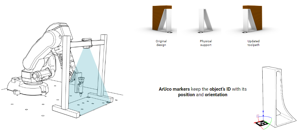
Therefore, this research thesis seeks for an Additive Manufacturing Control System that matches the digital printing models to physical references, such as supports or embedded external elements by marking, cataloguing, detecting their location through Computer Vision on a cyber-physical set-up and and updating the printing toolpath of the model.
Proposal
Print Point uses ArUco markers to define and catalogue this external elements that will become the reference of the updated toolpath of the printing model.
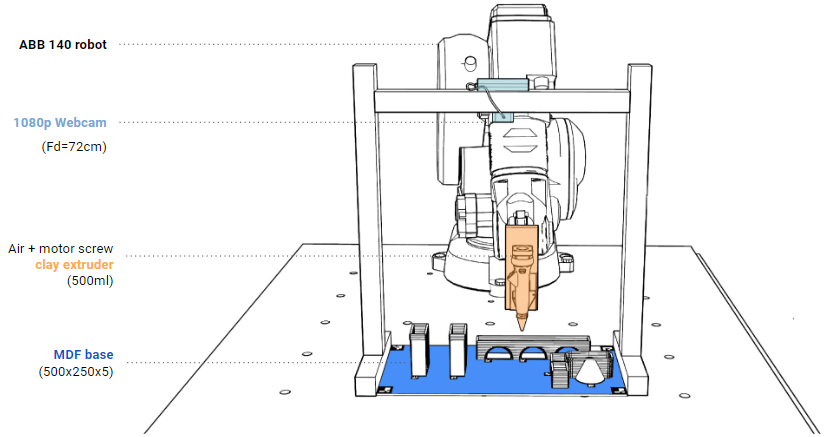
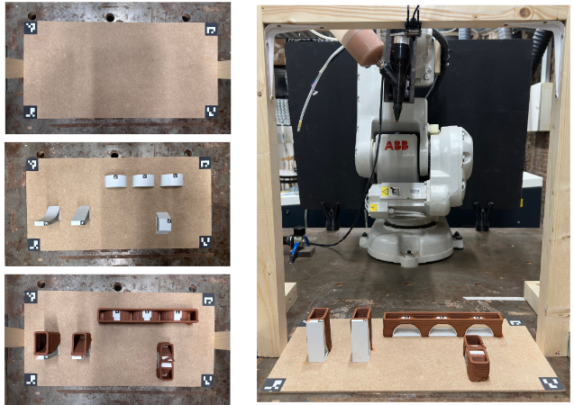
Set-up
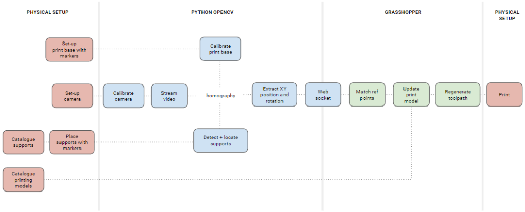
Workflow
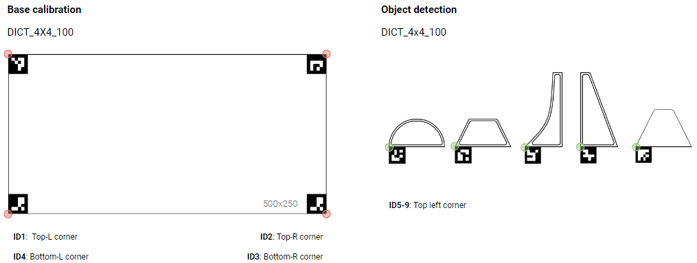
Data Catalogue
ArUco markers are used to calibrate the printing bed corners (0-3) and define the different elements (4-n) mathing the coordinates of one of its corners with the digital model geometry reference point.
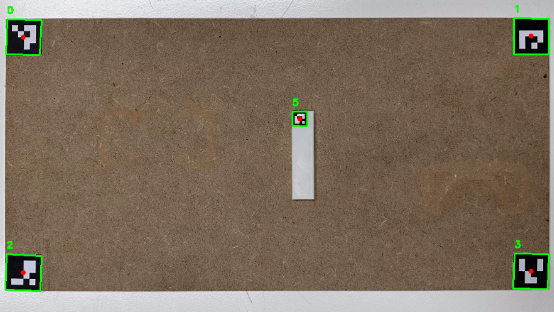
Data Collection
After calibrating and undistorting the image captured with the camera, the markers’ corner position and orientation of the arUco is defined through computer vision. The image is cropped masking the boundaries of the 4 corners of the printing bed and setting the top left one as (0,0). The location and orientation of the elements’ markers are defined through homography in reference to the new coordinates.
Data Implementation
The calibration and object’s marker points and transformation vectors are streamed through a web socket to the Grasshopper script to update the location and orientation of the digital model using the GHowl plugin on a local WiFi network.

Final Results
CASE STUDY
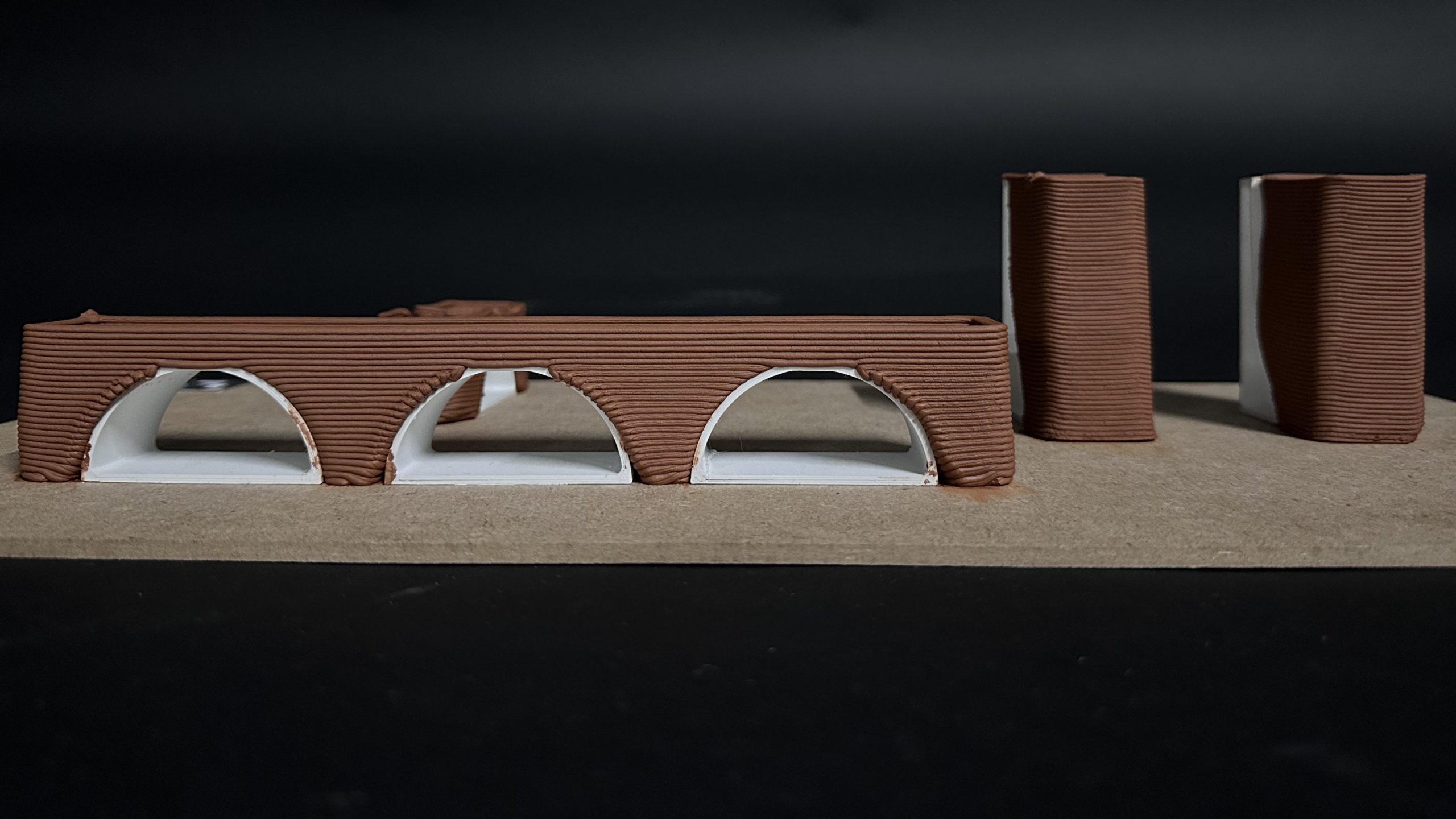
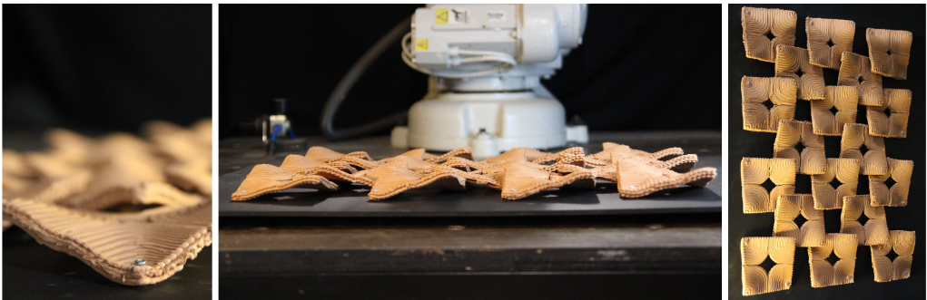
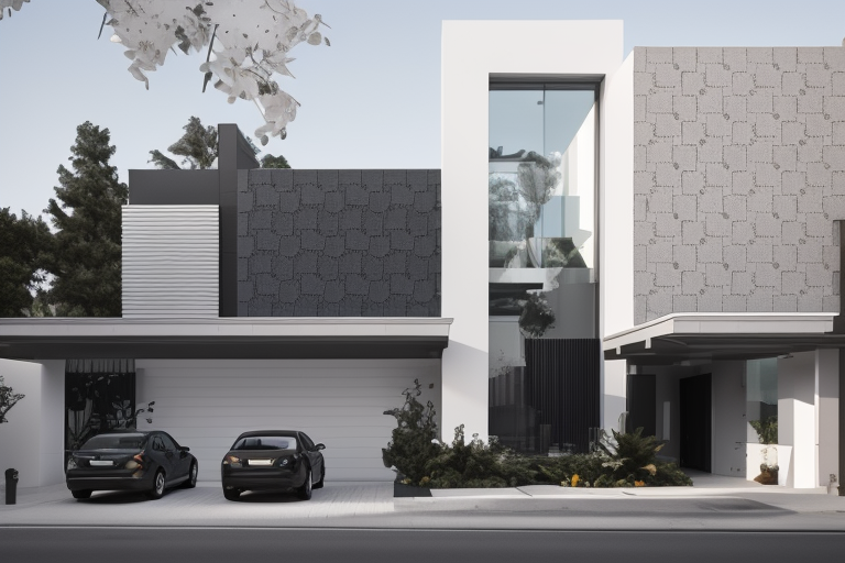
In order to validate the concept of my research, I implemented this methodology involved in a workflow capable of generating a series of printed elements requiring the use of supports due to specific design requirements. The goal was to create a replicable design suitable for use as tiles on a façade.
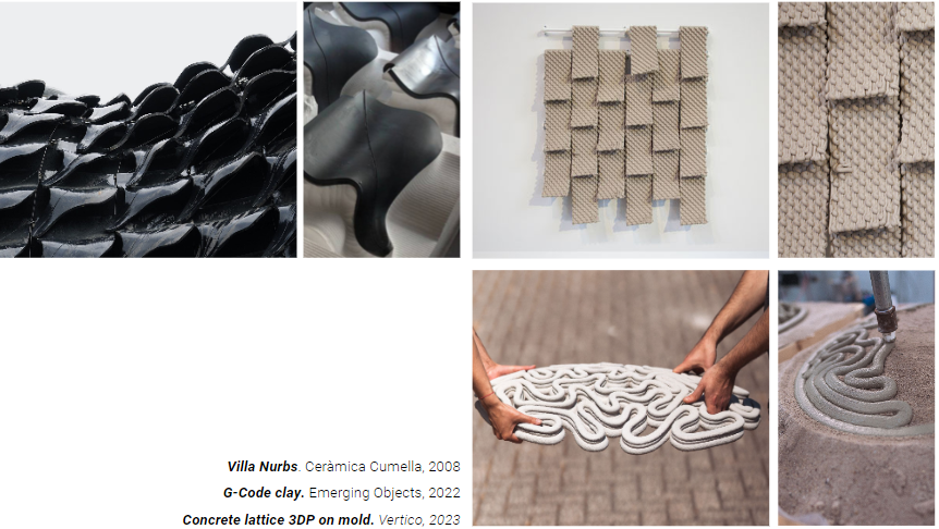
State of the Art
After reviewing various references of shell or tile designs that could potentially adapt their shape or fabrication process to hybrid manufacturing or physical supports, it became evident that none of them took advantage of the opportunity to use external elements to replicate the process.
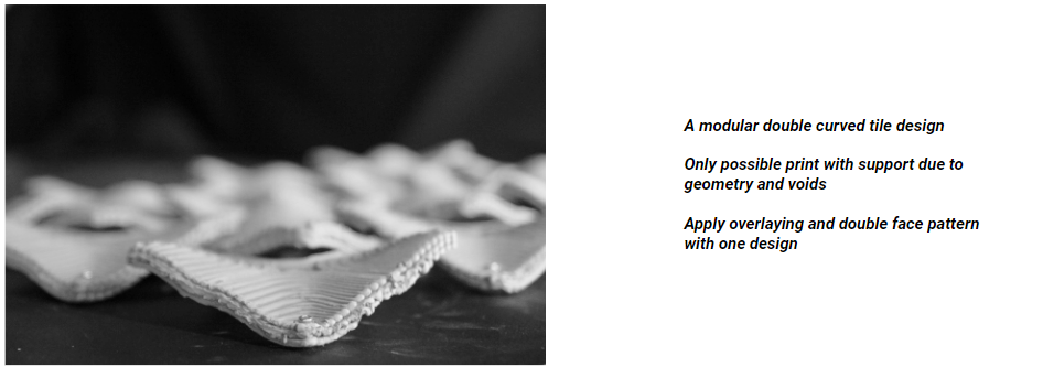
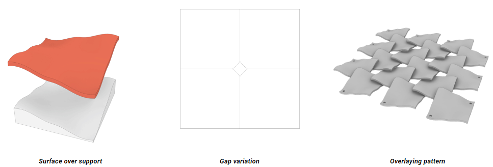
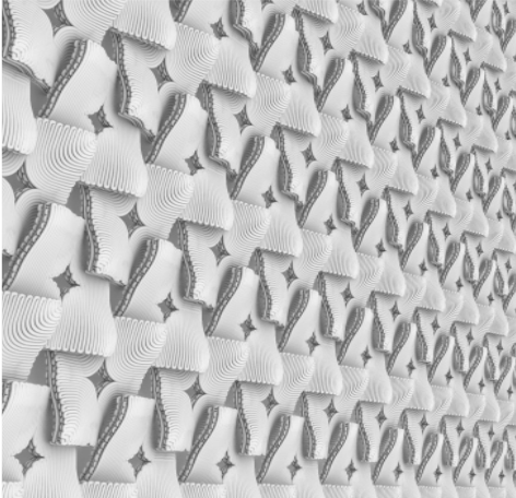
Design
The design allowed to use both faces of the print and have multiple variations of the gap dimension, giving a wider range of options to generate different patterns. The assembly overlaying the tiles would add a new design value with casted shadows and filtered light on the surface.
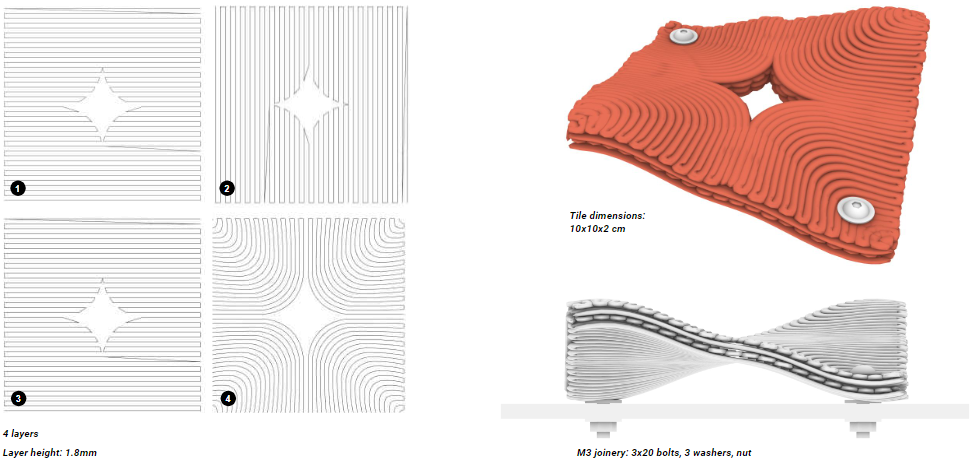
Toolpath design
The tiles were made of 4 layers, crossed vertical and horizontal, and offset curves from every corner.
A post process phase would include 2 bolts on every tile to assemble them onto any surface or structure.
Toolpath simulation
Printing time of every tile: 9′ 20″
Video
Assembly and final shots
FURTHER IMPLEMENTATION
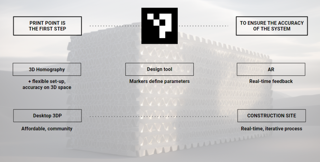
Print Point just took its first step, proving that the accuracy of this process fulfills the requirements of the proposal given to my hypothesis.
But the potential applications and pathways for this technology are vast and can be adapted to numerous fields. Upgrading the detection and location of elements not just on the base of the print, but anywhere in the 3D space on any moment of the printing process, or defining the markers as boundaries or conditions of the print as design tools are just some of the potential uses of this tool. But the key aspect of this methodology is that can be implemented from the most affordable DIY setup for desktop 3D printers to the most complex and high tech processes that require a bigger accuracy and reiteration of known geometries in a bigger scale or uncontrolled set-up as construction site.
All the information and material needed to implement immediately this methodology is provided at this Github repository.
