Integrative Concept
Introduction
The goal of the integrative modeling seminar is to transition this design from a computational model into Revit, enabling us to generate construction documentation, schedule project’s elements, and assess the overall project data, therefore the performance of our concepts through KPIs.
Concept
Our Team’s vision is to create the Enso hyper building. A building which is embedded in the Japanese culture through the Zen concept of circularity and cycles.
Our team, in charge of the industrial concepts, will be focused on the topics of energy, food and waste.
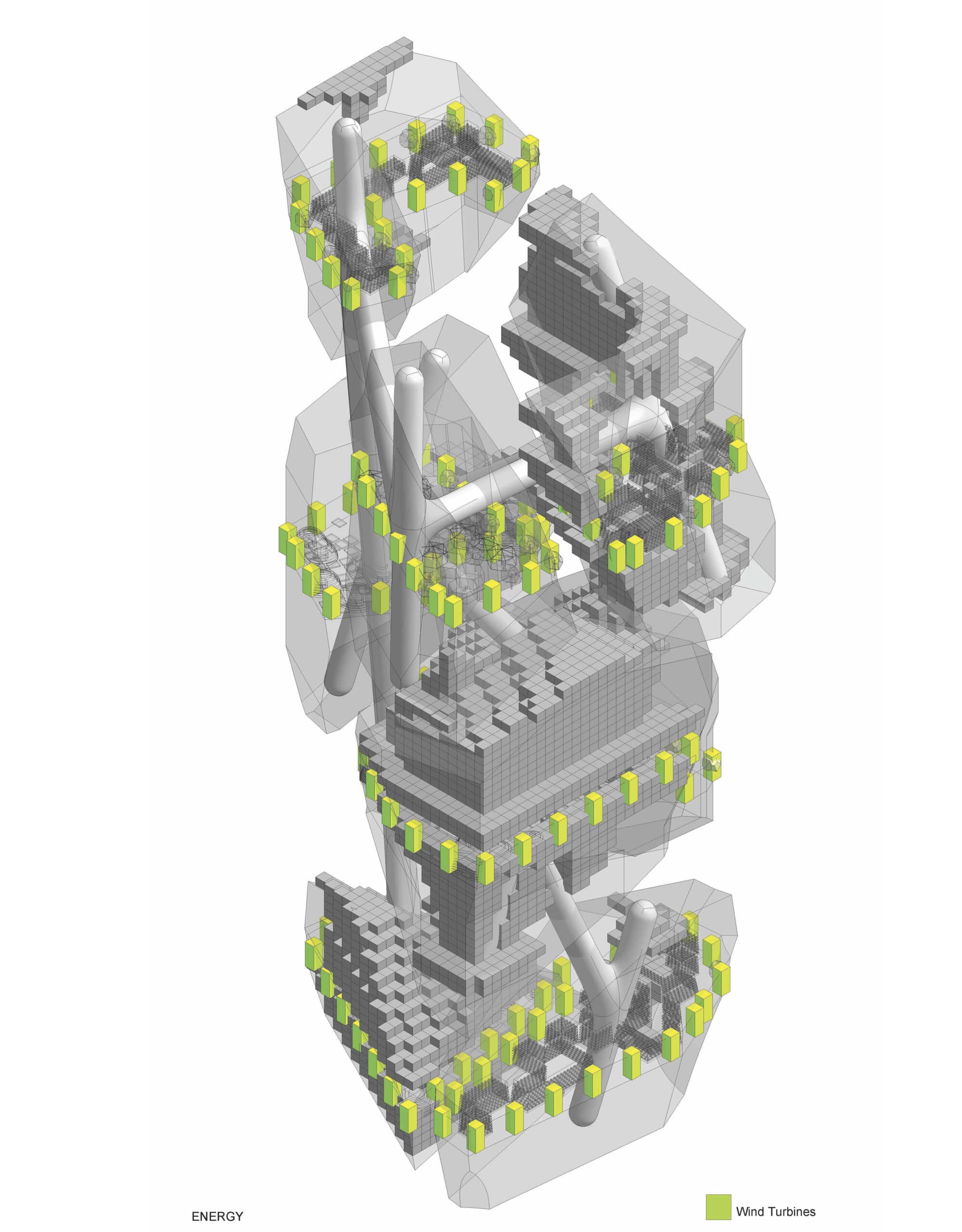
Energy
All energy is derived from renewable sources, stored effectively, and reused in interconnected systems. Waste heat from HVAC, data centers, and appliances is recovered and repurposed for heating water or spaces.
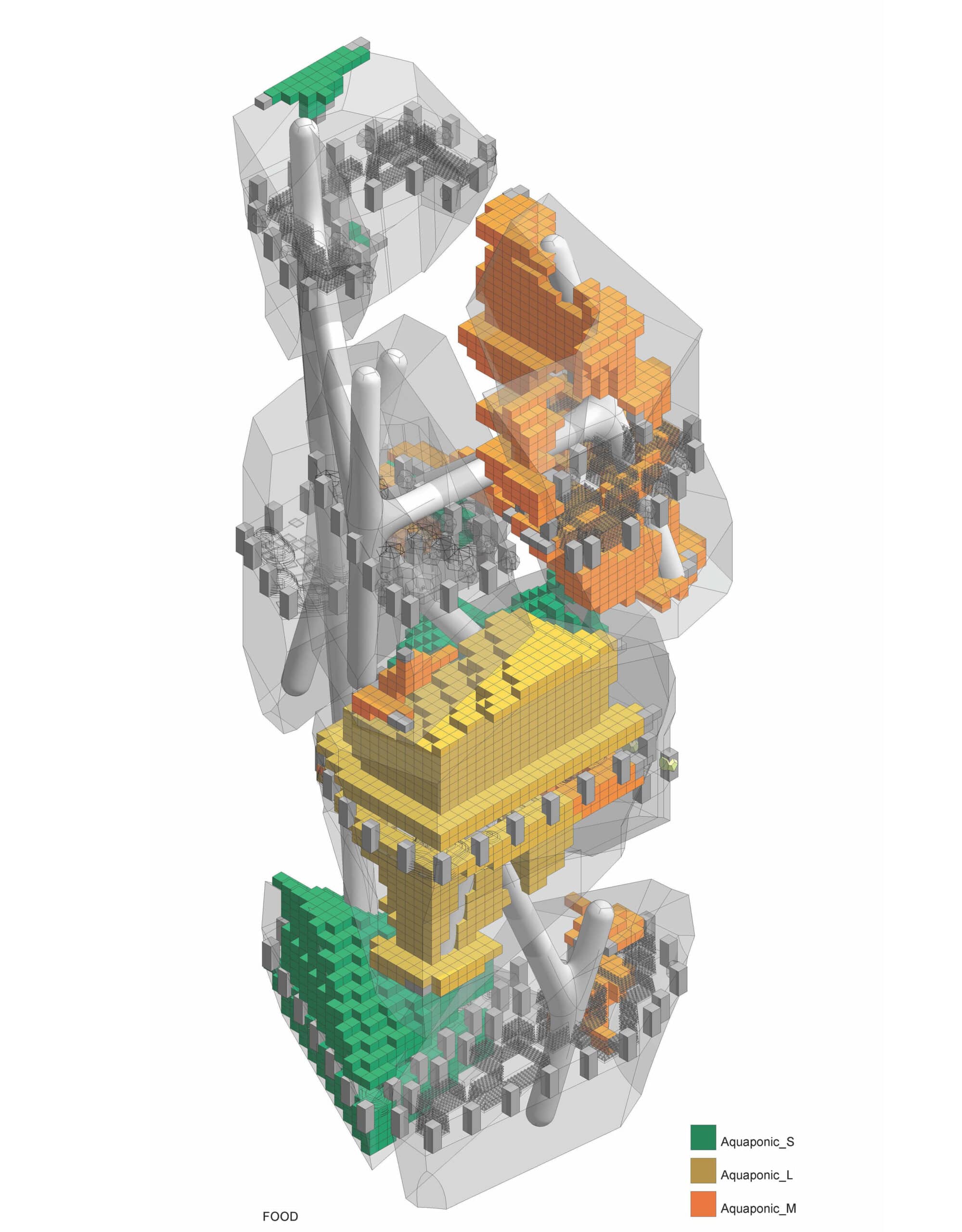
Food
Food is produced on-site through vertical farming, aquaponics, and urban agriculture, delivering fresh, nutritious produce while reducing food miles and waste.
These systems integrate seamlessly into the architecture, turning every level into a source of sustenance and ecological growth.
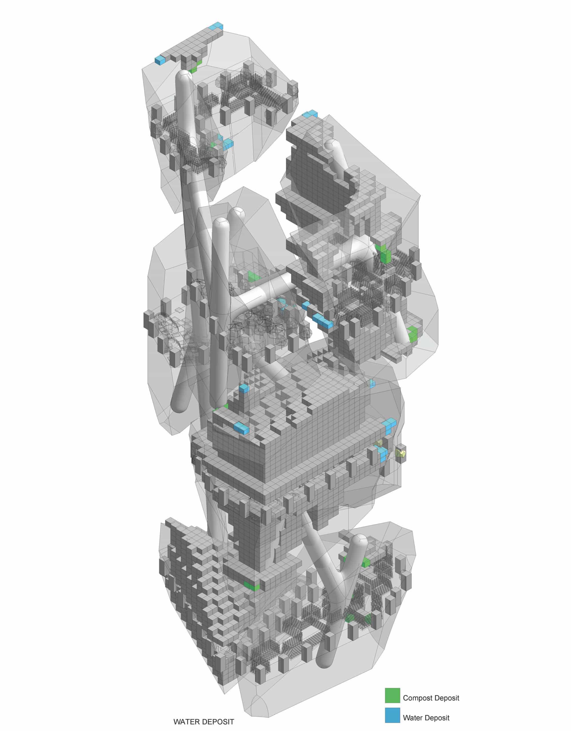
Waste
Waste is eliminated as a concept, with every output—from organic to construction debris—transformed into valuable inputs through circular processes, fostering zero waste. Composting, biogas generation,recycled water and material reclamation systems close the loop, creating regenerative resource flows.
Integrative Modelling
This post aims to expose the main workflows carried out for integrating our proposal in a BIM environment. So that we can apply them to future projects we develop. There are two main work blocks. The first one contains the 3D geometry development workflow and its parameters. This block is done simultaneously by using Speckle, Grasshopper and Rhino Inside Revit. Afterwards Revit will be the software where we will dump the geometry and from where the final documents will be produced.

DirectShapes
The first main strategy that we used to implement our project into the BIM environment was the use of Direct Shapes.
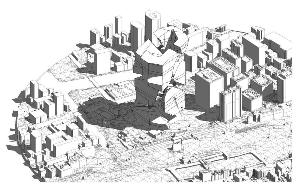
Context
Through this approach we integrated the models that are not part of our scope, such as the urban model, the general massing from the service team and the structural model from the structure team.
Massing
To perform the volumetry we face the same strategy as during the realization of the Context but this time we add a parameter to each of the pieces that later we would use to overwrite its color by filters.
Integrative Process
Native Revit Elements
After this first contact with the environment and the general form of our project we are ready to proceed to the creation of levels within our volumetry and everything is automated within our definition of Rhino Inside Revit.
Levels
Creating levels from Rhino Inside in an automated way offers great advantages over conventional ways. Traditionally done by manual copying and insertion of heights (which generally a greater chance of error).
With Rhino Inside Revit the repetitive process is avoided generating the tables of levels in an automatic way with their respective names and properties.
Slabs
For the creation of native Revit slabs, a simple operation is performed to intersect the planes associated with the levels with the massing. This intersection will give us the perimeter of each forged. It will only be necessary to choose the type of forging desired and associate these perimeters with their respective level.
In our case we also added a “Neighborhood” parameter that specifies the relative position of the level with respect to its Neighborhood.
Integrative Families
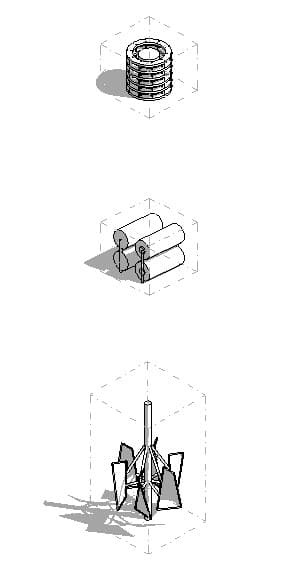
Levels of Detail
In the initial stages, raw voxels serve as placeholders for refined geometry in the design development phases. To optimize performance, we implemented three levels of detail (LOD), allowing faster visualization while working, while preserving high detail for specific worksheets. This setup is managed using Rhino.Inside, leveraging Revit’s native LOD system.
LOD 100
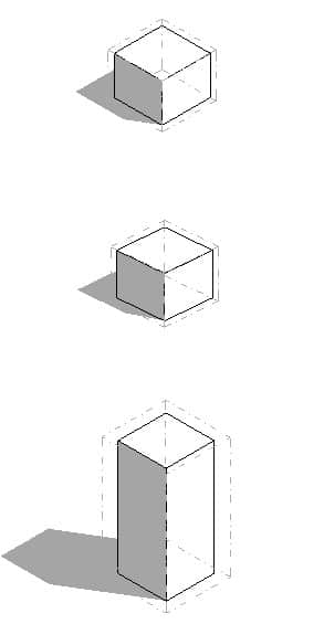
LOD 200
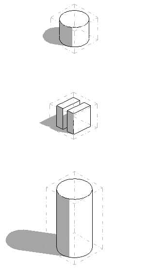
LOD 300
Integrative Workflows
Filters
With the established families and parameters, we introduced automated filters in Grasshopper. This enables seamless adaptation of specific concepts—such as food height—while instantly generating corresponding legends. Not only are the filters automated, but shared parameters allow rapid filtering of different family types.

Location Filters
For a quick reading of the families that make up each of our 3 blocks we made an independent filter of each one so that we could highlight their location in the whole volumetry.
Energy
Food
Waste-Water
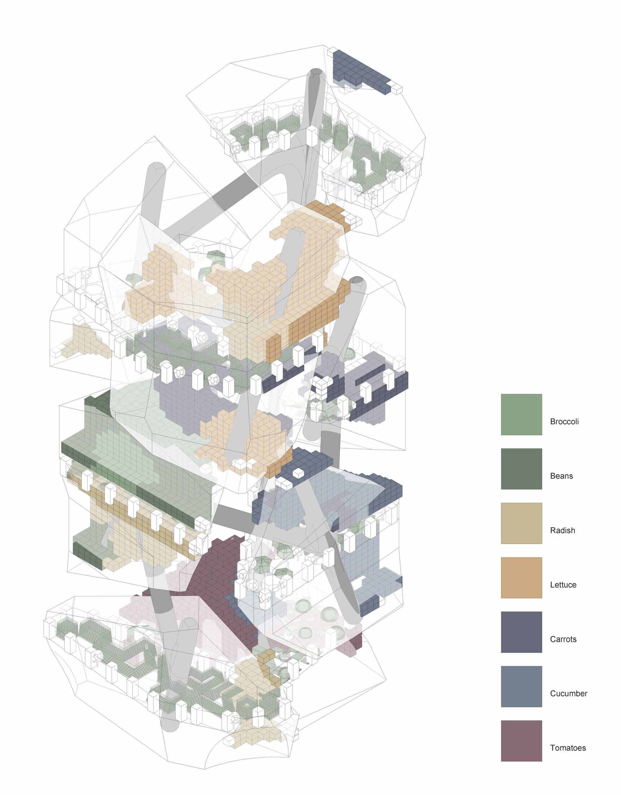
Food Filters
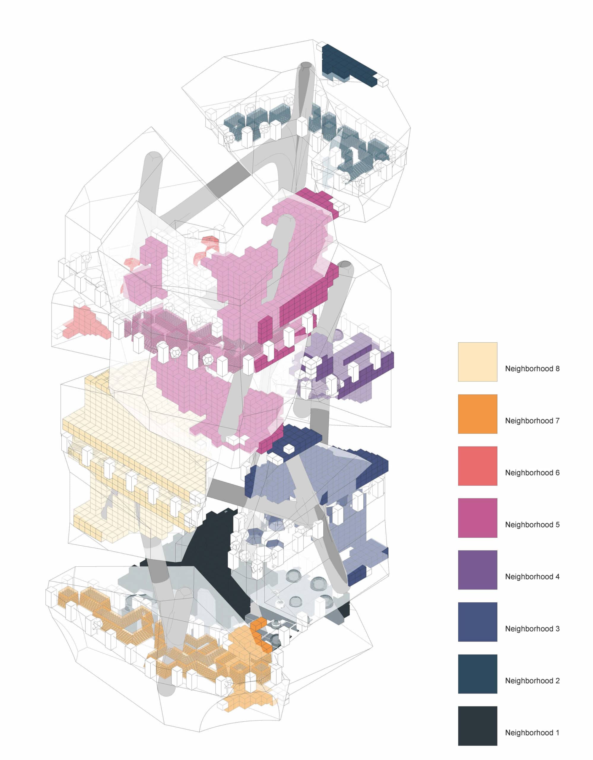
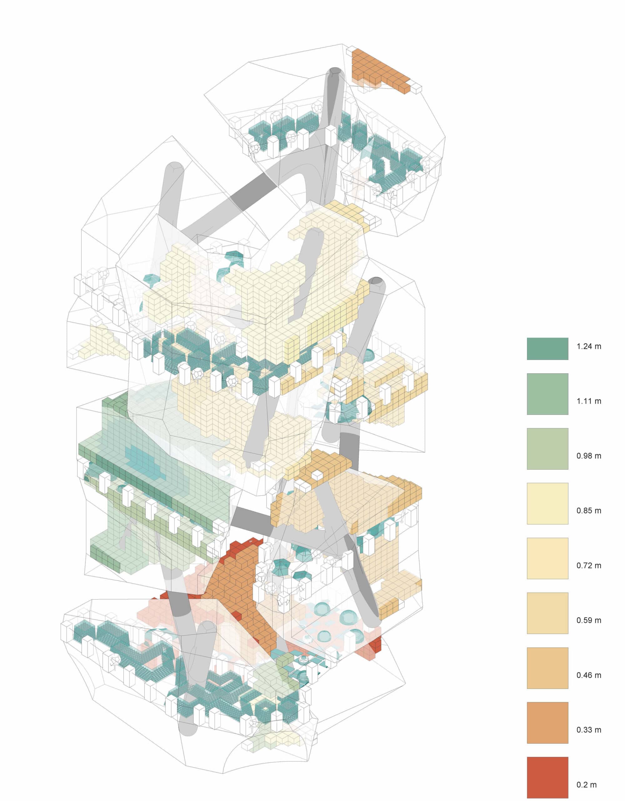
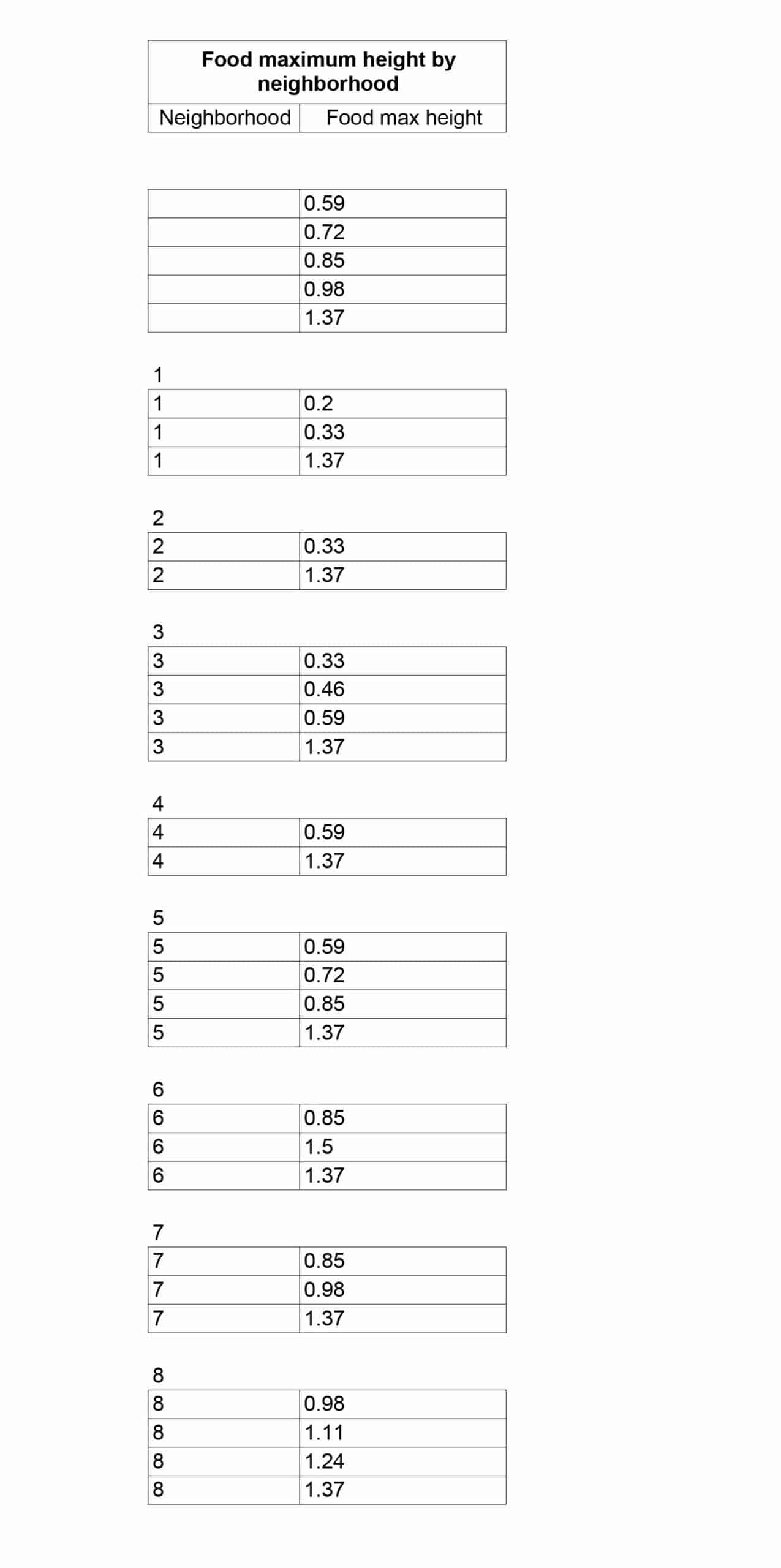
Our largest families are the food-related ones. In order to visualize the complexity of these families and their types, we also made visualization filters where we specify the type of food produced, its location in different neighborhoods and the height that the food produced reaches
Food Type
Food Neighborhood
Food Height
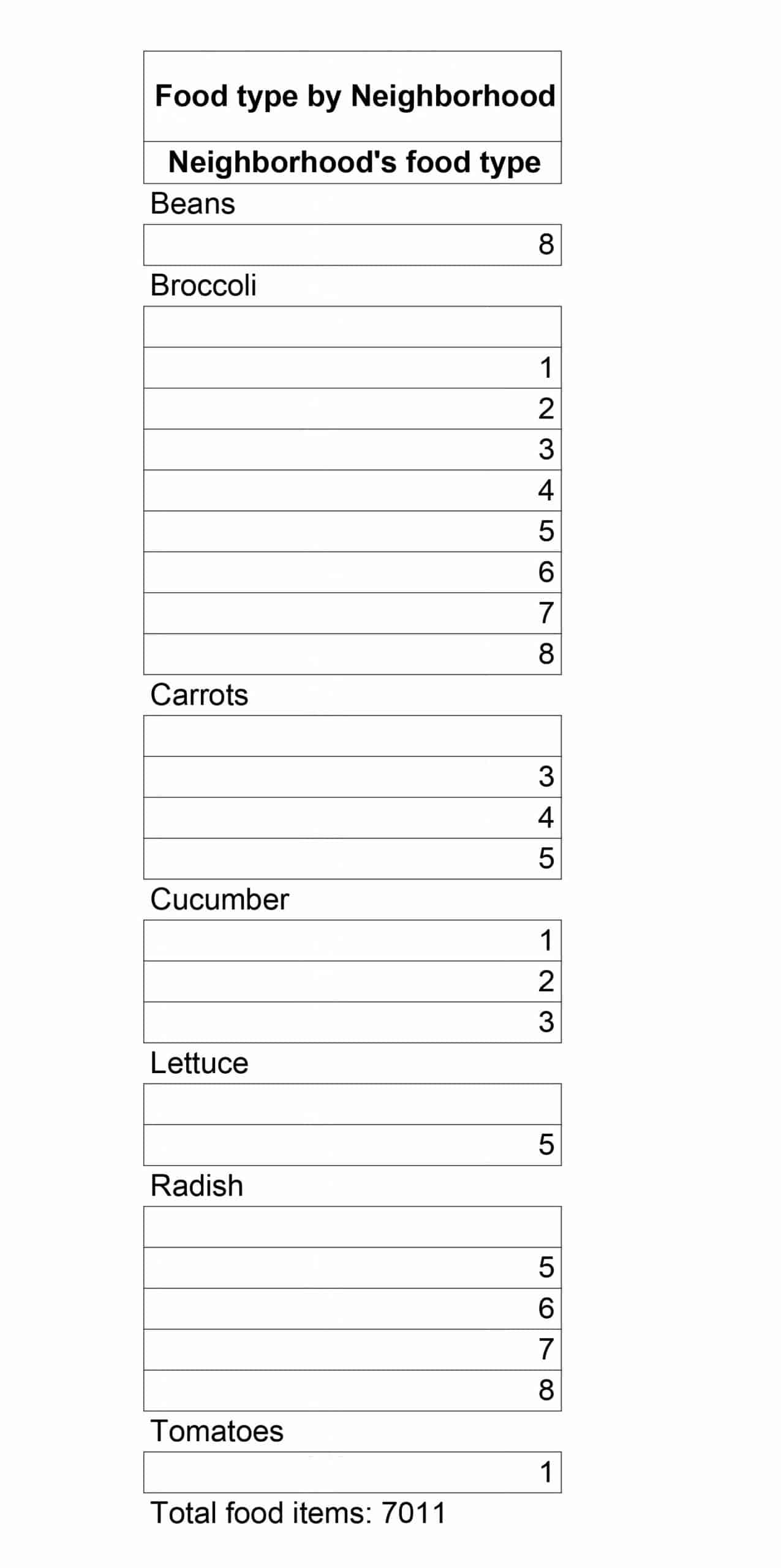
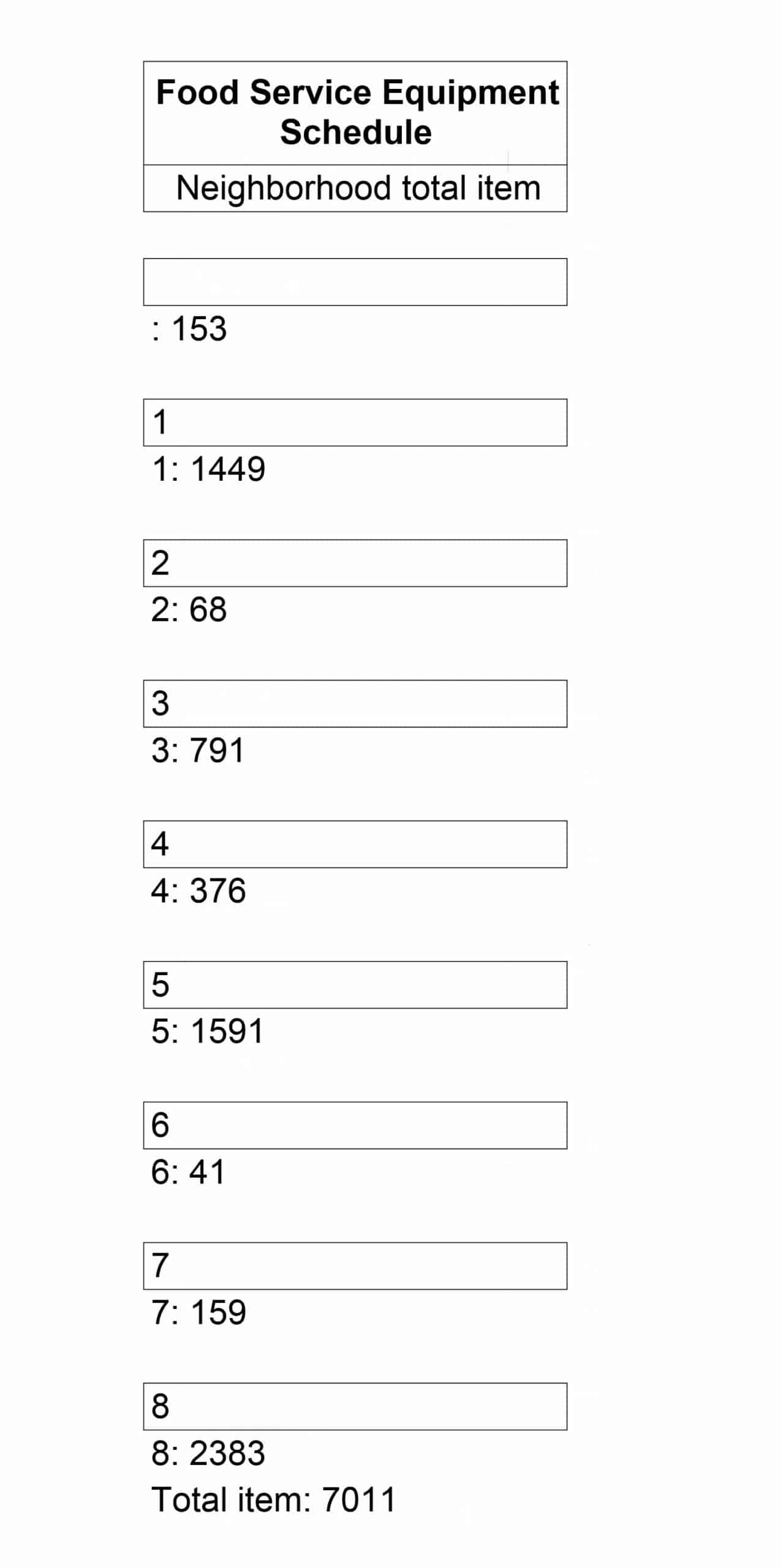
Schedules
Schedules are primarily managed in Revit, while family type creation and mass assignment are transferred from Grasshopper to Revit. This workflow improves tracking and performance analysis of industrial elements, as demonstrated in our examples.
Food Type
Food Neighborhood
Food Height
Sheets
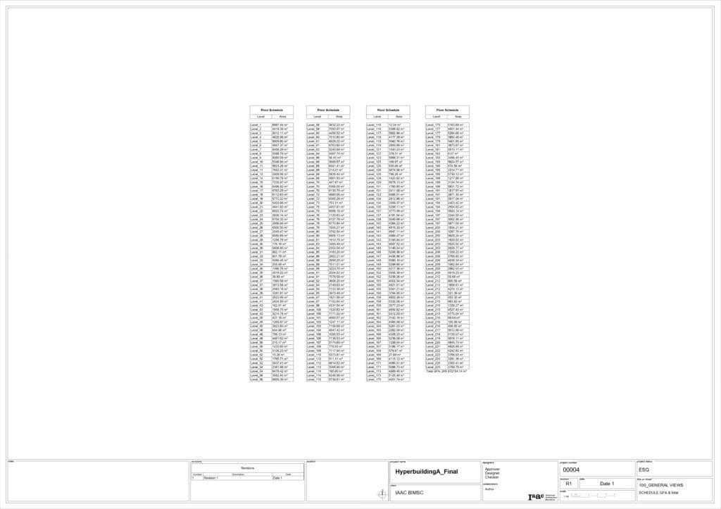
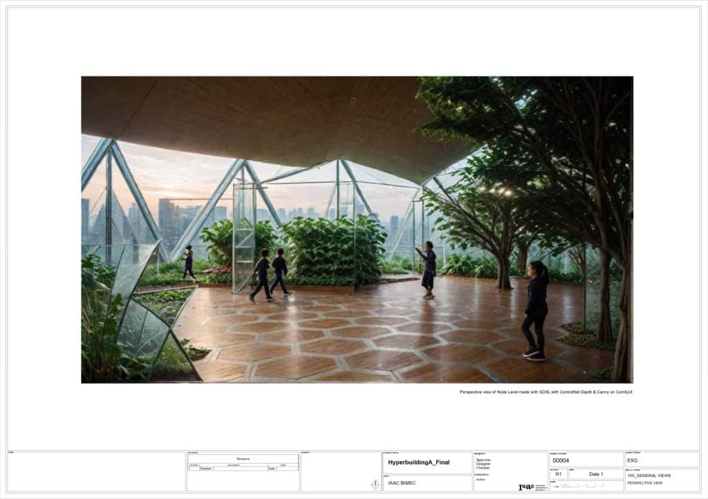
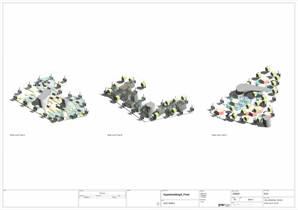
Finally for the creation of sheets we use again Rhino Inside Revit. The creation of legends and views for the sheets are generated simultaneously in the process. Then you will proceed to finalize your layout within them. Some of the documents of the corresponding delivery are as follows:
Floor Schedules
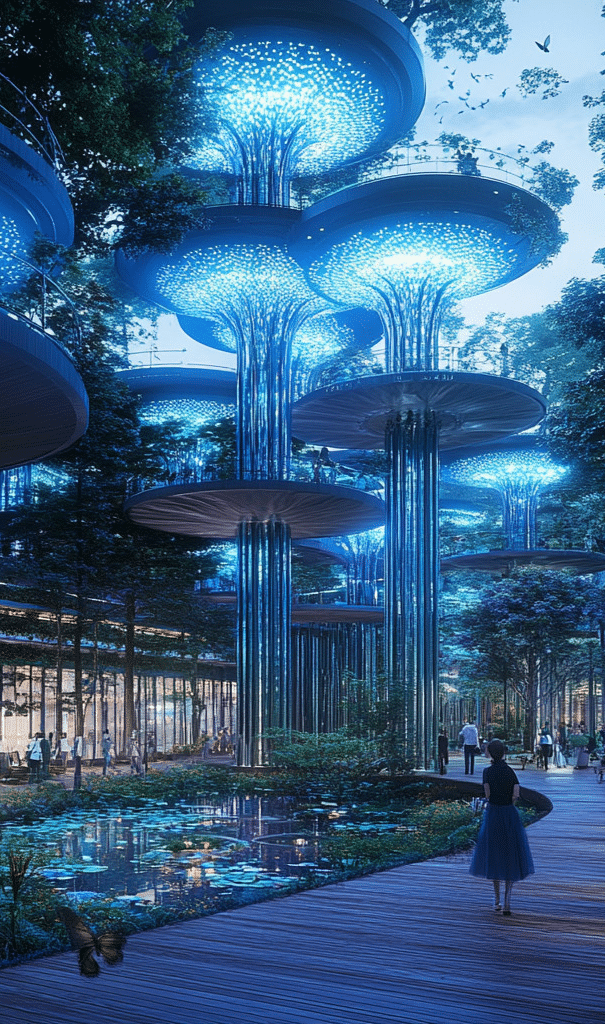
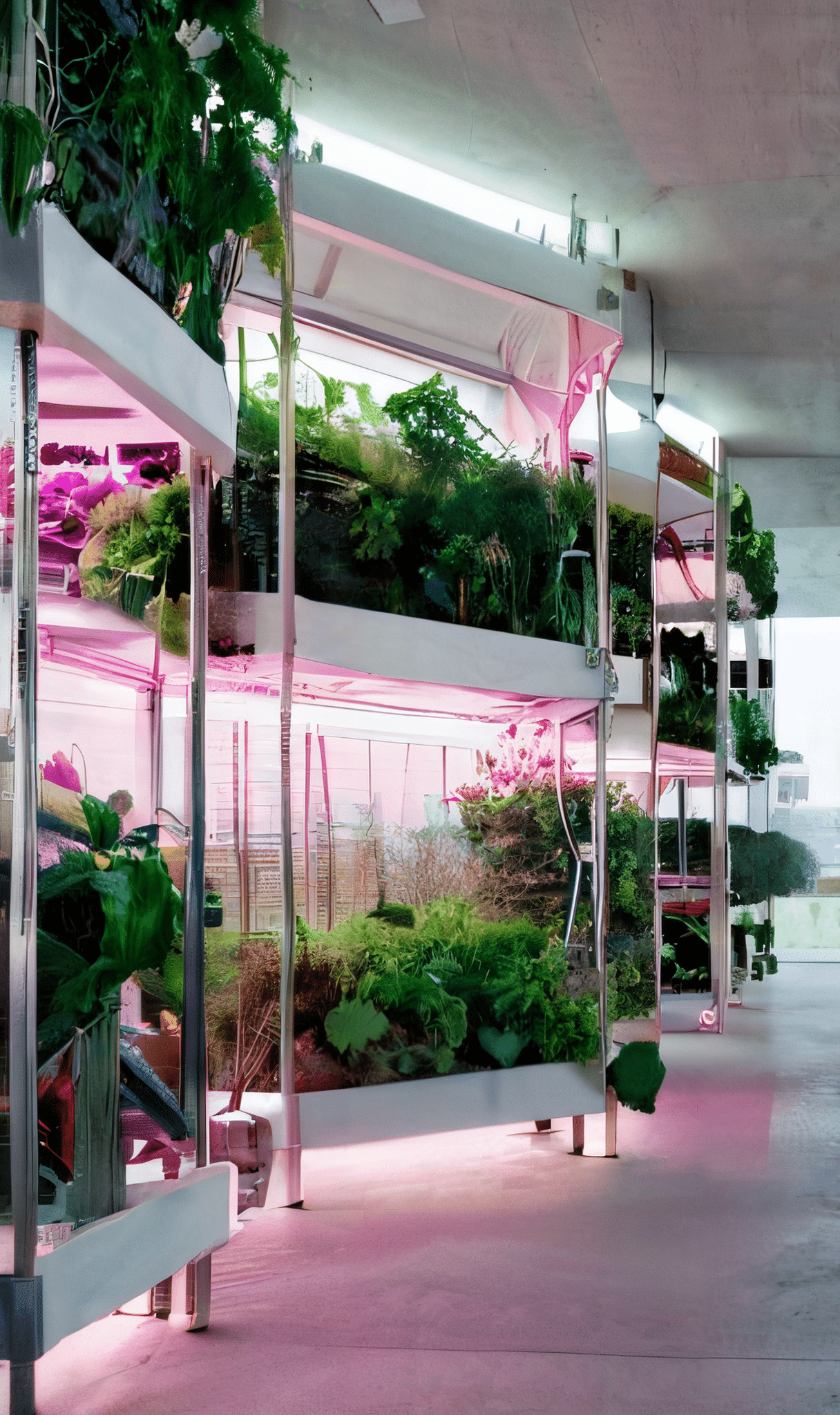
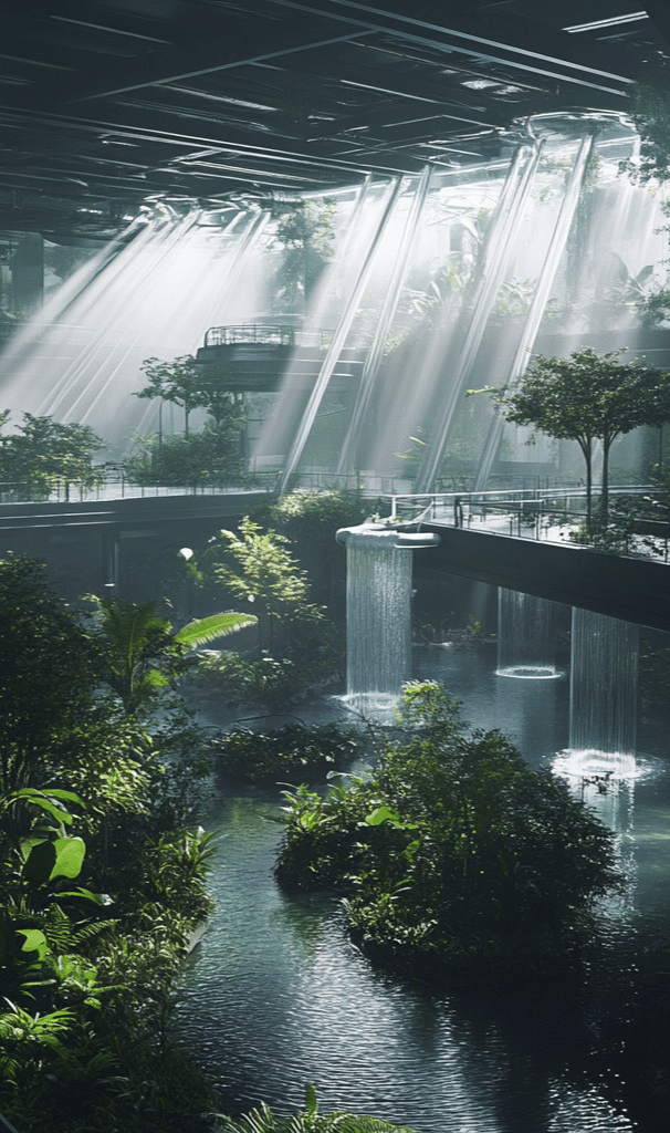
AI generated image
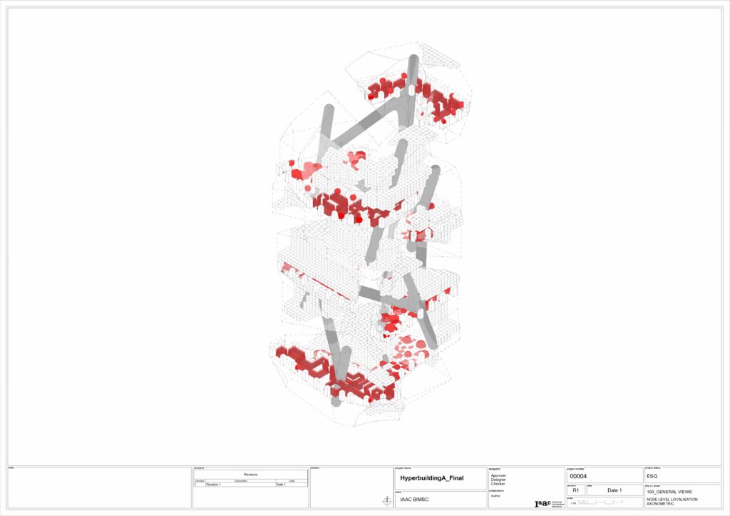
Node Levels’ Location
Node Levels’ Types
Challenges and Opportunities
Challenges
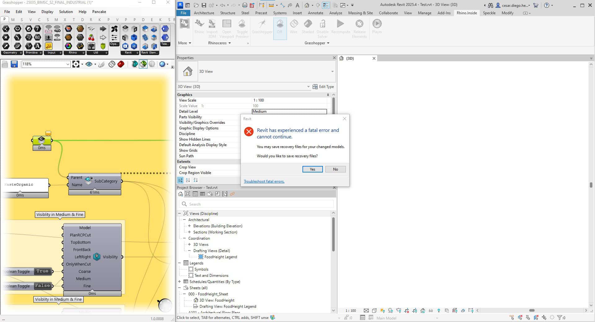
The primary challenges encountered were related to the computational demands of the processes. As the geometry became more detailed, even with the use of Level of Detail (LOD) models, the system occasionally produced fatal errors. Loading new components also required longer processing times. In some cases, alternative solutions such as distributing scripts were needed to support implementation.
Opportunities
The opportunities remain significant. Once the tools and their capabilities are well understood, they can greatly improve the speed of geometry creation and automate repetitive tasks. This brings considerable benefits.
Several workflows explored during the integrative modeling course show strong potential for further development and application in professional settings. These include
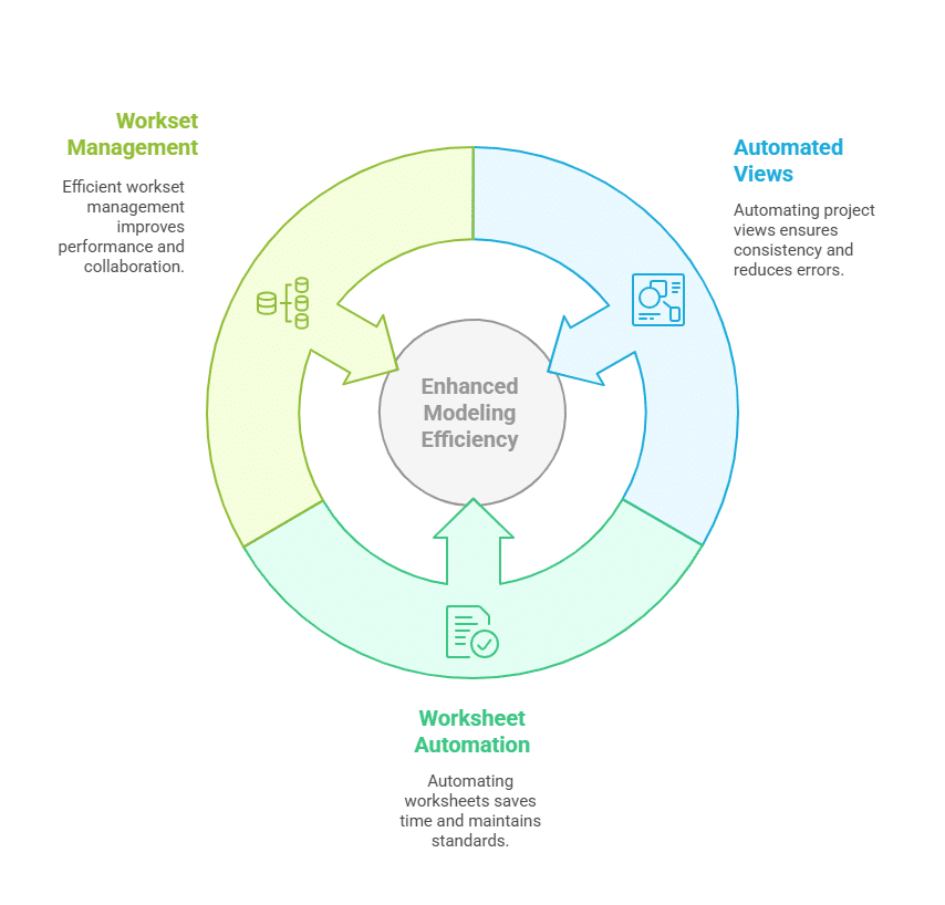
- Automation of views, filters, and associated legends:
- Streamlining the generation of project views through automated rulesets helps maintain consistency and reduce manual errors. Automatically applying filters and generating corresponding legends ensures visual clarity and project-wide standards, which are especially beneficial for large or complex models.
- Automation of worksheet creation, including views, legends, and title blocks
- Automating the setup of worksheets significantly reduces the time spent on documentation. This includes placing predefined views, populating legends with relevant data, and automatically assigning title blocks with correct metadata (e.g., project name, sheet number, and scale), ensuring uniformity and compliance with documentation standards.
- Automated workset management for lighter and faster modeling
- Efficient handling of worksets improves model performance and supports better team collaboration. Automation can assign elements to appropriate worksets based on rules or categories, reducing manual sorting efforts and helping maintain a manageable, high-performing model environment.