
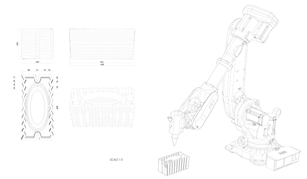
The project involves a large geometric form designed for clay 3D printing, consisting of 6 identical sections. This article will present the results of our analyses that explore the technical challenges and opportunities of this geometric design during the clay fabrication process.

The workflow begins by rationalizing the pavilion structure into 6 symmetrical parts, isolating one section to define properties for both outer and inner shell systems, establishing the printable unit as the fundamental module. The isolated section undergoes surface-based subdivision into 50 modular units, with division following surface geometry and topology to maintain geometric continuity. The geometry is then sliced using non-planar curves that follow local surface normals, adapting to complex inner and outer contours, with slices cleaned, simplified, and re-ordered to form collision-free print paths through multiple overlapping layers where the first curve defines the subsequent layer sequence via the final toolpath, while top/bottom surfaces receive optimal positioning. Finally, all units are systematically sorted and organized for production sequencing, enabling comprehensive geometric analysis pre-fabrication to ensure manufacturing efficiency and quality control in robotic additive manufacturing execution.
.

.
.
The proximity analysis evaluates toolpath segment distances to neighboring layers, identifying collision risks and over-extrusion zones through color-coded mapping where green indicates safe layer clearances and yellow/red highlights critical areas where toolpaths fall below minimum spacing thresholds. The top view displays overall safe and critical proximity regions, while the bottom view specifically marks high-risk contact zones where layers may cause collisions. A comprehensive 3D proximity map provides full spatial analysis, visualizing potential overlaps or surface collisions across the entire geometry. This pre-fabrication validation tool enables print orientation optimization and toolpath correction, ensuring collision-free execution in robotic additive manufacturing workflows.

The angle analysis evaluates each unit’s surface normal orientation relative to the printing direction, using color-coded mapping where green indicates printable angles within safe limits and red marks areas exceeding maximum allowed inclination. The bottom view displays angle accumulation zones, highlighting areas where angles stack up and create high-risk overhangs that require support or re-orientation for path correction. The top view reveals critical overhang angles, identifying which parts of the geometry have the steepest inclinations where red regions show angles too steep for stable non-planar printing and require orientation adjustment. Side view analysis shows printable regions in green while yellow/red areas indicate where angles approach or exceed the limit threshold. Based on angle and proximity analysis results, the final design was modified to be printed without top and bottom surfaces, removing these regions to eliminate critical overhang angles and close-proximity zones, ensuring a stable, collision-free non-planar print execution.
.
.
.
.
.
.
The workflow demonstrates how to rationalize complex architectural pavilions for robotic 3D printing through systematic subdivision, non-planar slicing adapted to surface geometry, and pre-fabrication validation using proximity and angle analyses to detect collision risks and overhang limitations. The process shows that successful large-format additive manufacturing requires iterative design adjustments based on technical constraints, ultimately removing problematic surfaces to achieve stable, collision-free fabrication.
