The first of the final three phases of the Techne, DETAIL, revolves around the collaborative project Living Prototypes (LP), which will be exhibited in Berlin’s AEDES museum in December 2022. LP, which has been in development for more than a year is a collaboration between three academic/professional teams: IAAC/WASP, ITKE/FIBR and CITA/COBOD.
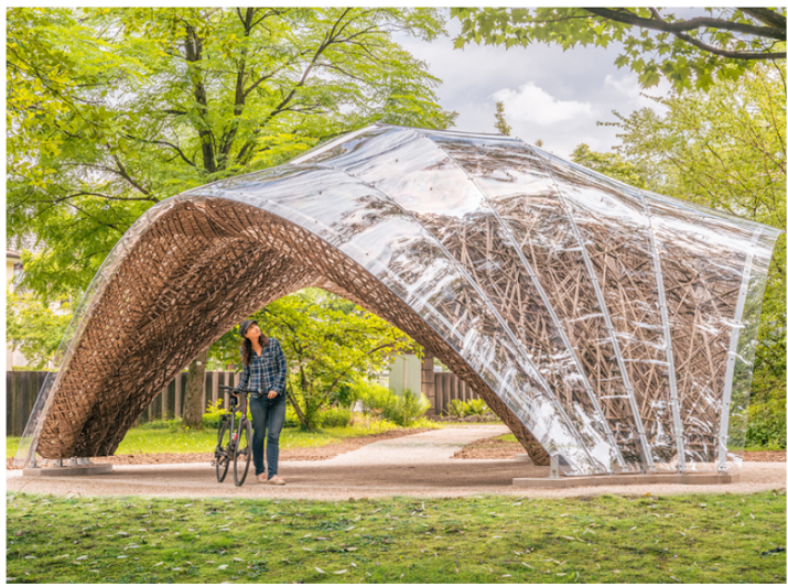

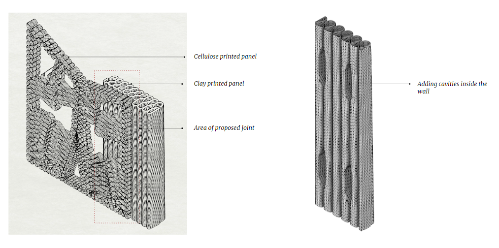
One of the main efforts of the project is the design and construction of a prototype that combines three materials and building techniques: earth-printed walls, cellulose-printed panels, and timber/fiber-weaved structural slabs.
The aim of this workshop is to work out the connections between the parts. There are four typical details: (1) clay to fiber, (2) clay to cellulose – 1, (3) clay to clay and finally (4) clay to cellulose – 2. Four groups of 3 to 6 students had 5 days to research, test, print, and draw possible solutions for the details.
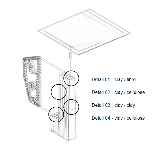
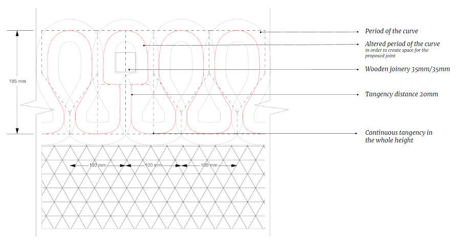
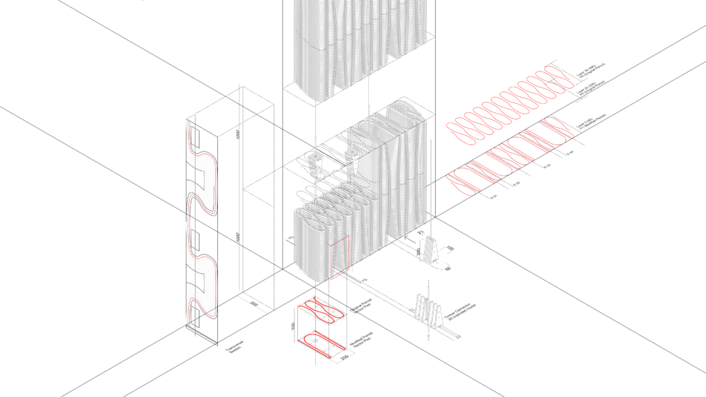
To start the design, the students were given a preliminary exhibition layout and more importantly, the base toolpath pattern for the Clay walls. For the DETAIL workshop, all walls were designed with a bottom width of 35cm and a top width of 20cm. Other assumed printing dimensions: layer thickness of 15mm, a print width of 40mm, and a 20mm material overlap between tangential printing paths.

Detail Design
1. Clay to Fibre
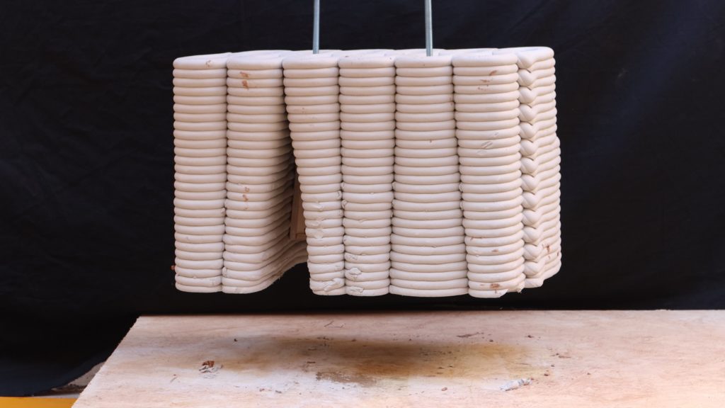
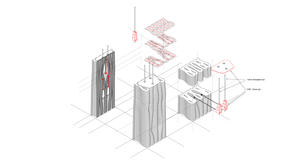
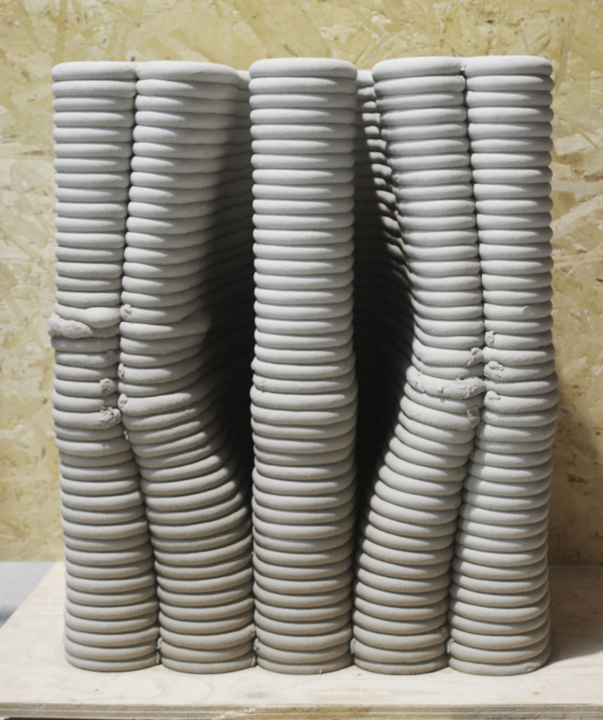
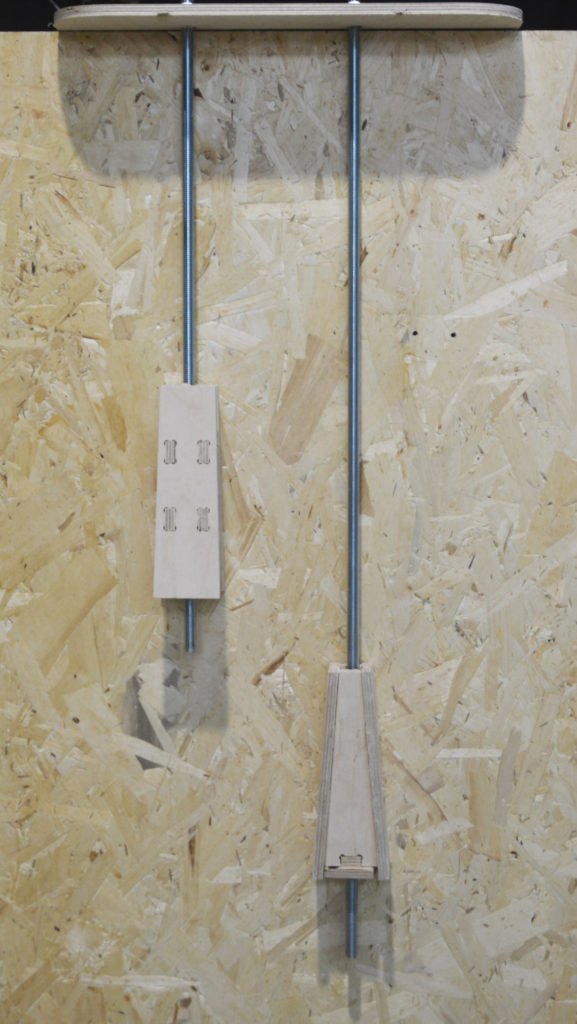
To realize a connection between the clay walls and the roof slabs (flax fiber + timber) from ITKE, the students explored an idea to partially post-compress the clay. The idea is to use threaded rods (3 per wall-rood connection point) coming down into the clay from the roof. Along these rods, wooden keys/anchors are fixed to post-compress the layer in between them.

To place these keys within the wall (after drying) openings are made in the wall. These openings are made by sliding tangents within the base pattern. To keep a continuous printing path within the wall and minimize the geometrical impact on the wall, the disturbance of the base pattern is minimized as much as possible.
2. Clay to Cellulose 1
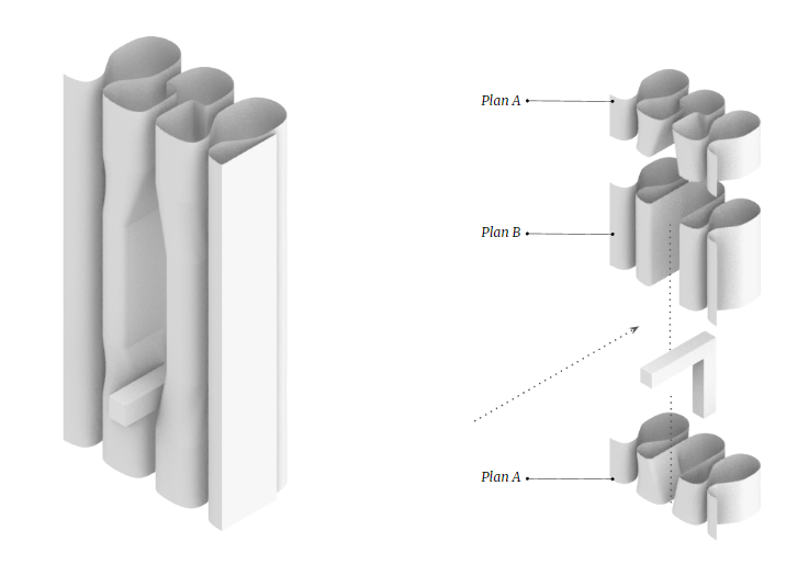
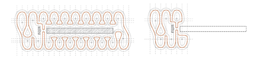
The first Clay to Cellulose connection is a wall-to-panel joint that holds up two panels from one side. The students decided to explore different ways to create wall cavities to allow for wooden details to enter the wall and lock the cellulose panel into place.
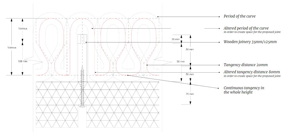
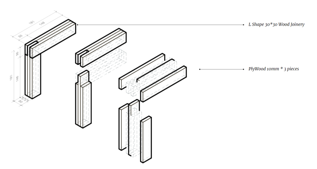
To create these cavities, two different printing paths are needed to loft the desired geometry. Plan A is both the bottom and top of the cavity and shows a narrow loop to hold and sit tight around the wooden insert. Plan B show to opening in the wall’s façade to allow for the insertion of the insert, and to screw in the panel.
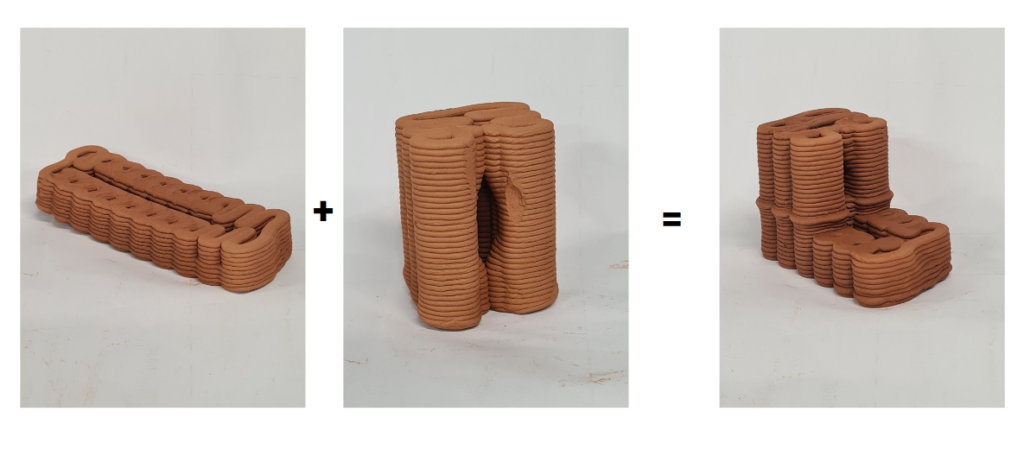
3. Clay to Clay
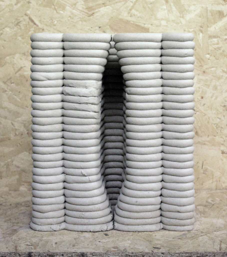
The Clay to Clay detail has multiple functions in the project. First, it holds two wall segments, that are on top of one another, together. The wall is divided into segments because of transport concerns. The clay walls will be printed in Barcelona and then shipped to the exhibition in Berlin. As the clay is very heavy, segmentation allows for a more secure shipment. But by cutting up the wall another concern arises. How do the top pieces get lifted into place? This is the second function that the Clay to Clay detail has.
To solve the detail, the students started by exploring, in drawing, modeling, and small-scale printing, different strategies to hold the wall segments together.
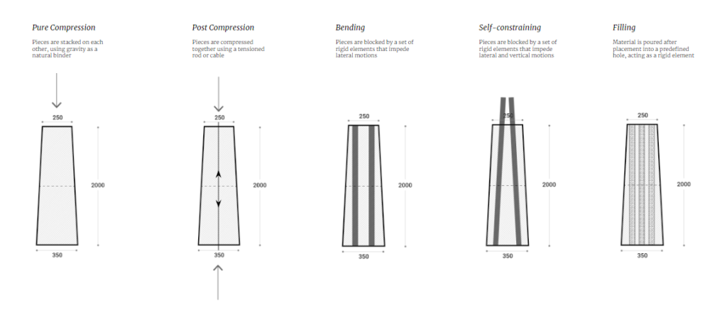
After comparison, the choice was made to further explore a post-compression strategy. Similar to the Clay to Fiber detail, the detail utilizes a wooden key and a tensor (either a threaded rod or a cable). Not only does this detail compress the segments together after installation, but it also allows the use of the keys and tensors to lift the pieces into place first.

Proximity analysis: clay to wood
The final wall had cavities at the bottom, to place keys for the post-compression, and in the middle to place the keys for lifting/transport.
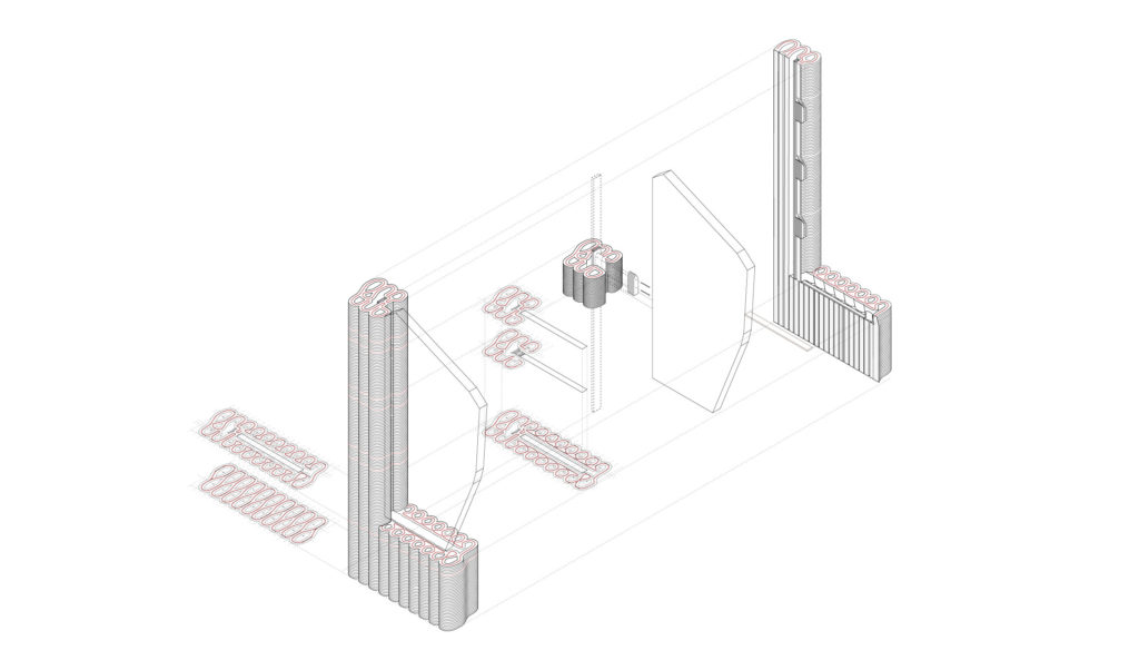
4. Clay to Cellulose 2
This detail seeks to solve the connection between the clay wall and an embedded cellulose panel. The exploration takes into consideration the extrapolation of the developed detail into a constructive detail as a facade-window connection.
The panel is supported on the side and at the bottom by the clay wall.
The infill of the wall adapts to embed a vertical wood profile that punctually opens laterally to allow the placement of the screws that anchor the panel.
The geometry of the wall in the vertical face of the connection is slightly shaped to hold the edges of the panel. At the bottom joint, the infill of the wall is also modified to place a horizontal wood profile which will be the base of the joint. The panel is screwed to this wooden piece. The profile is hidden inside the wall and the panel rests on it.
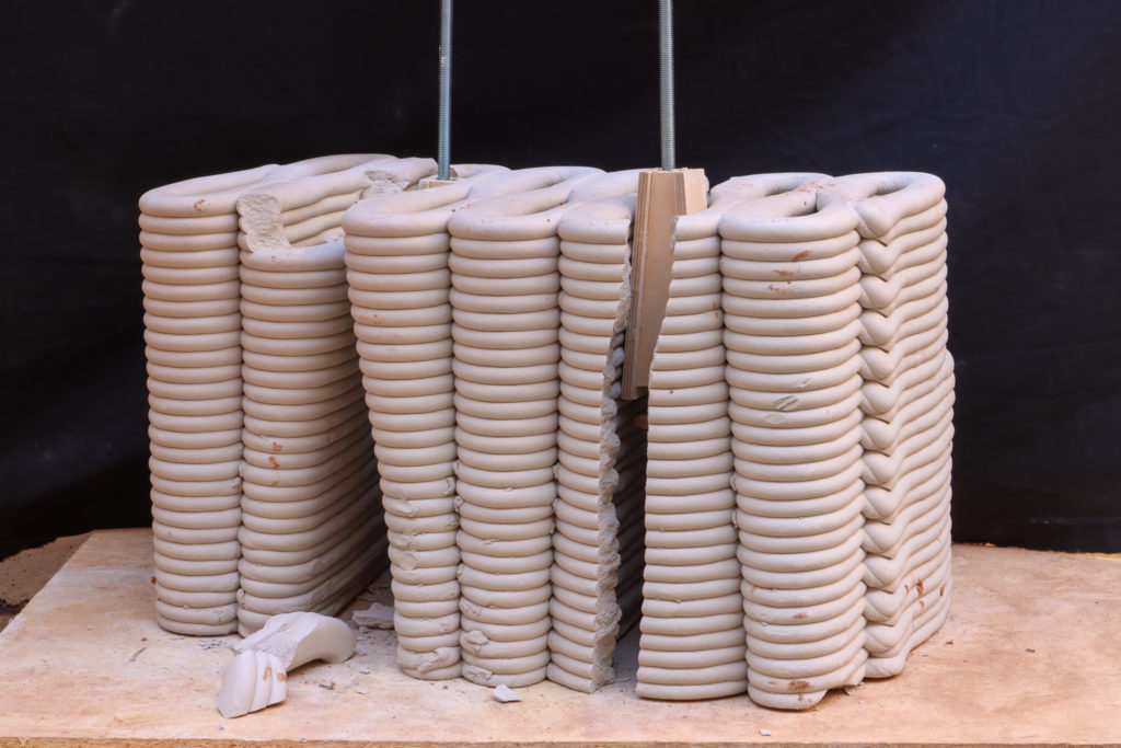
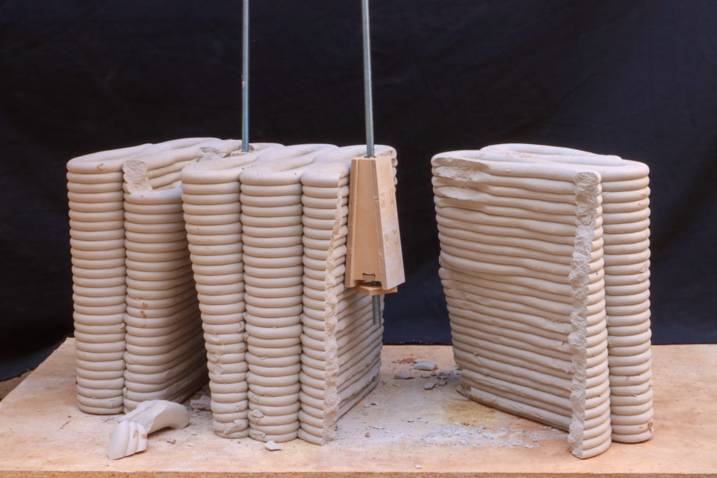
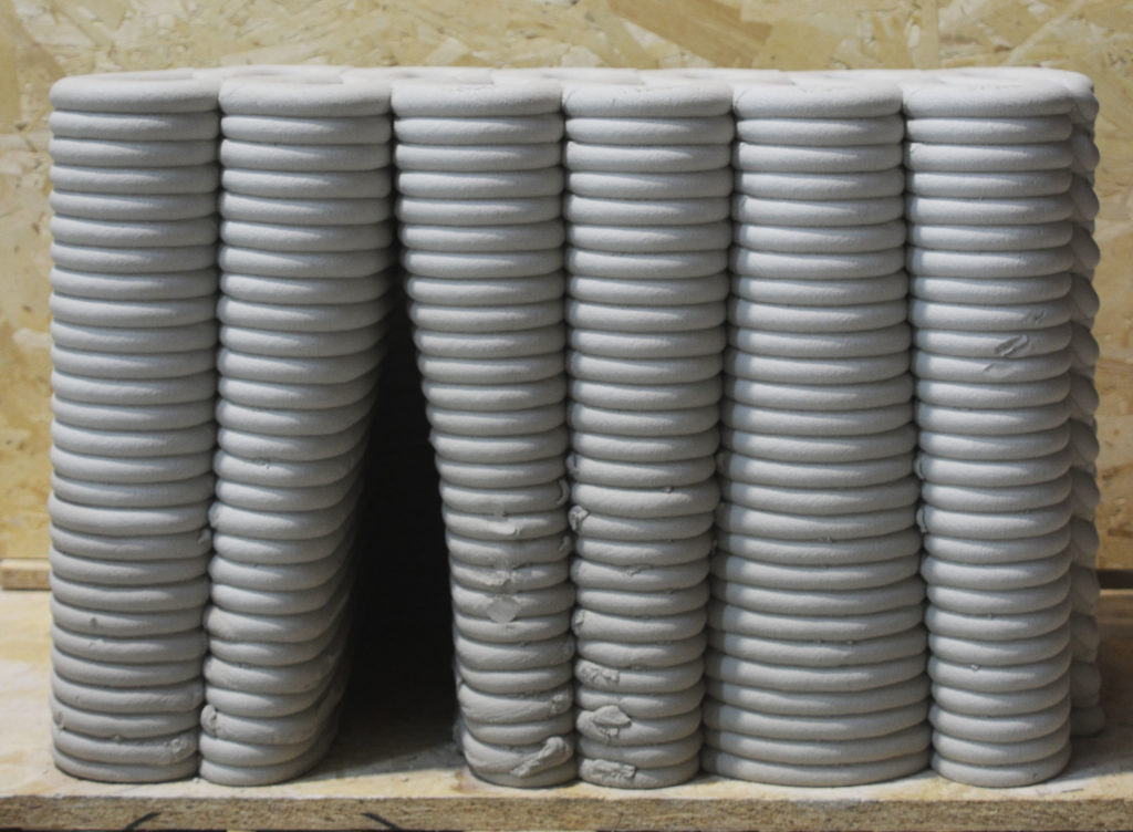
1:1 Prototype Prints
At the end of the week, all details were partially printed on a 1:1 scale using a KUKA KR150/L110 with a WASP printing end-effector. These were the student’s first prints using a robot of this size and allowed for an extra learning moment in preparation for the production of the eventual exhibition pieces.
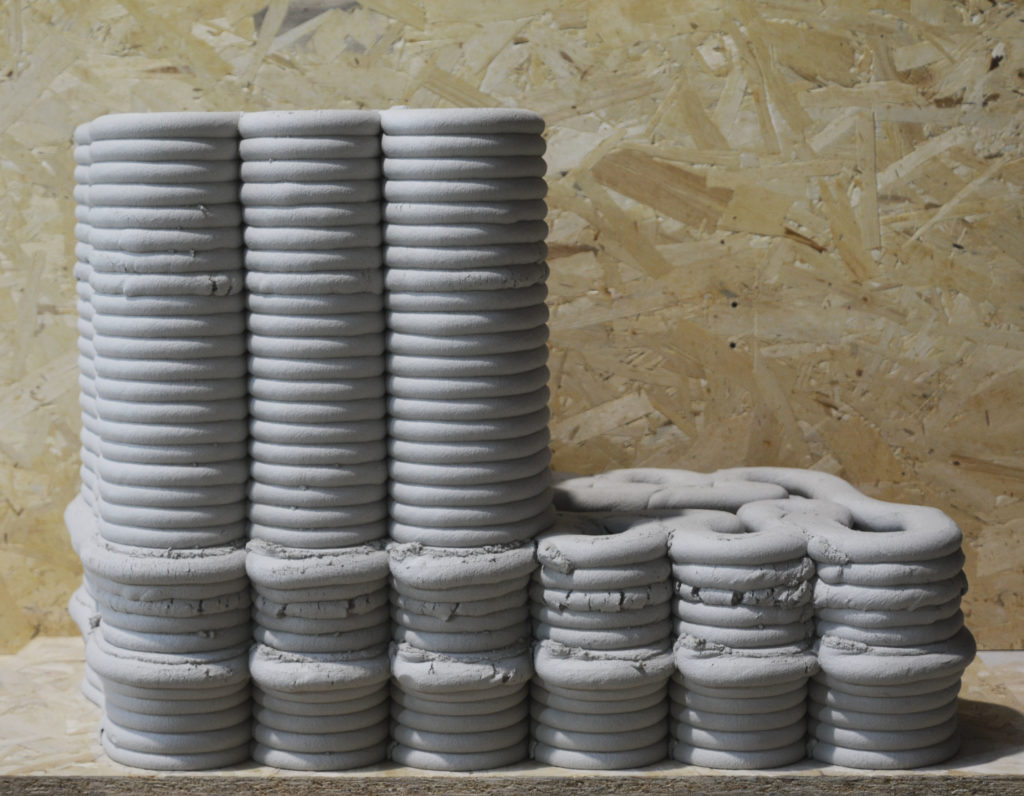
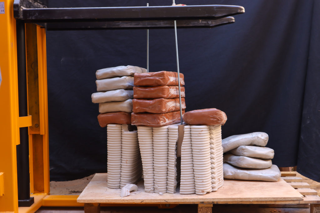
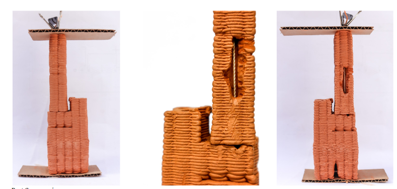
1:1 Prototype Load Test
After the pieces dried, we experienced a load test over one of the pieces. This allowed to make a rough measurement of how string this clay/wood key combination would be. Each bag is 12.5 kg.