
(Continuation from the first term. To view the Term01 click here : https://blog.iaac.net/dust-up-design-behavior-thesis-cluster-term-01/)
Material Research – Strategies

To solve the issues from the Term01, approaches from different scales were implemented. From material scale, adding marble dust can give more stability to the mixture and help it move less during printing. Exploring different curve connections such as self tangent, half overlap and full overlap can help to keep the print in-tact and exploring design parameters can affect the global behavior of the print.
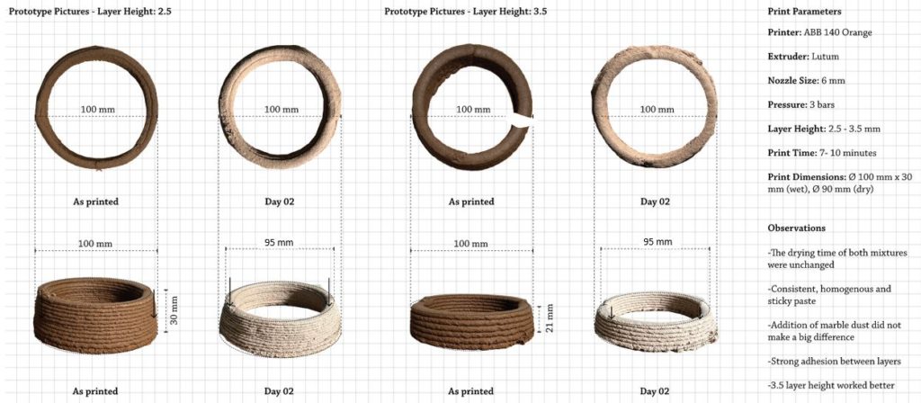
Firstly, the approach from the material scale was tested by adding marble dust to the mixture. It did not make a big difference. However, for scaling up it would have more impact on the toolpath.
Material Research – Design Parameters
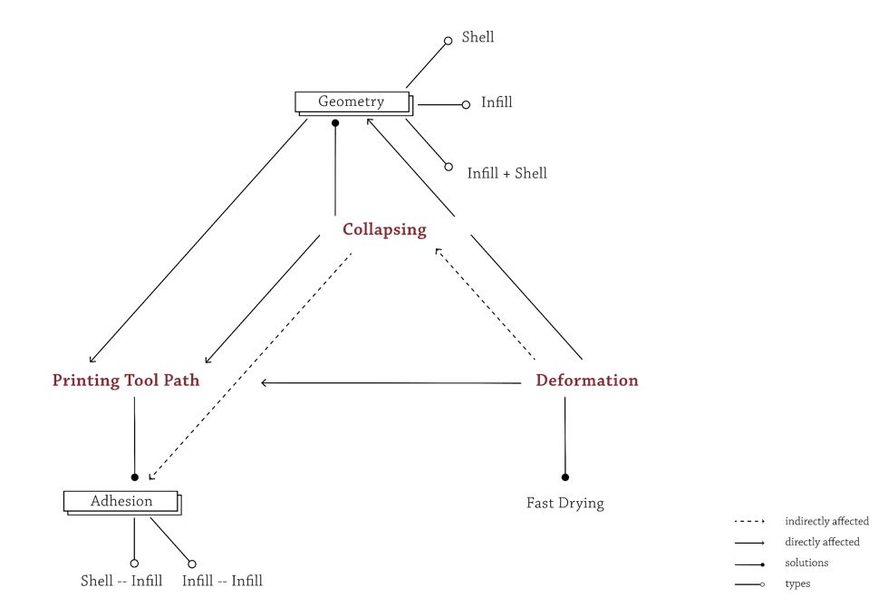
Next, for local and global approach defined the main problems and their possible solutions were defined. The three major branches are collapsing, adhesion and deformation. To prevent collapsing different types of geometries such as (shell, infill or both) can be explored and for optimizing the printing tool path two types of adhesion can be analyzed. To mitigate deformation fast and consistent drying can be done. The following geometries are designed to experiment and test these parameters and their relation to each other.
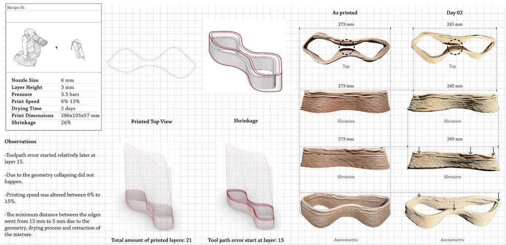
First test to address collapsing was to create a shell geometry. Tool path error started at a relatively later layer. The minimum distance between the edges (can be seen in top view as printed and dried) went from 13 mm to 5 mm due to the geometry, drying process and the retraction of the mixture.
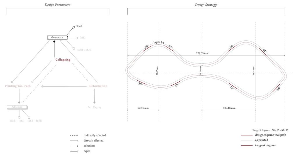
Different tangent degrees from 50 to 75 were explored.
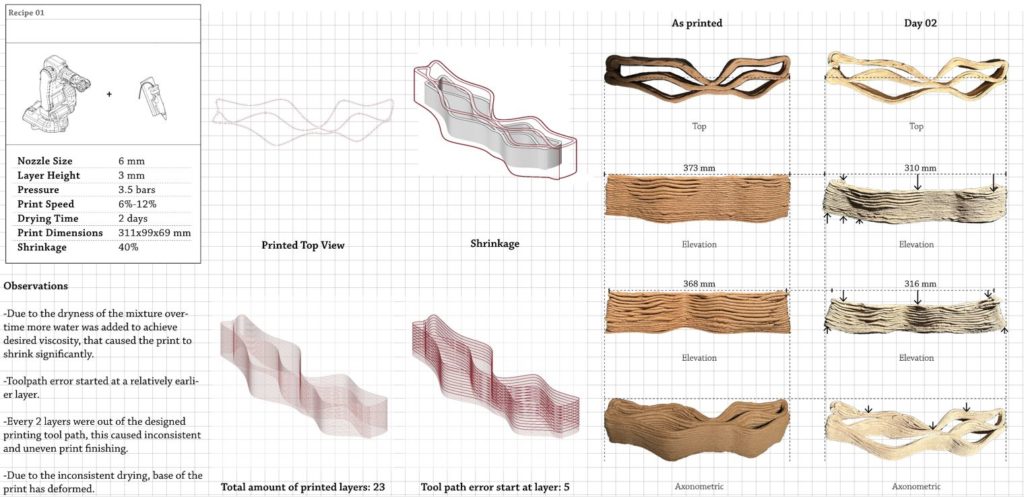
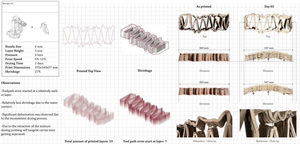
This geometry was created to test infill-infill adhesion. Due to the dryness of the mixture over time, more water was added, and this caused a significant shrinkage. Every 2 layers were out of the designed printing tool path, this caused inconsistent and uneven print finishing. Due to the inconsistent drying base of the print has deformed (as seen in elevation dry pictures).
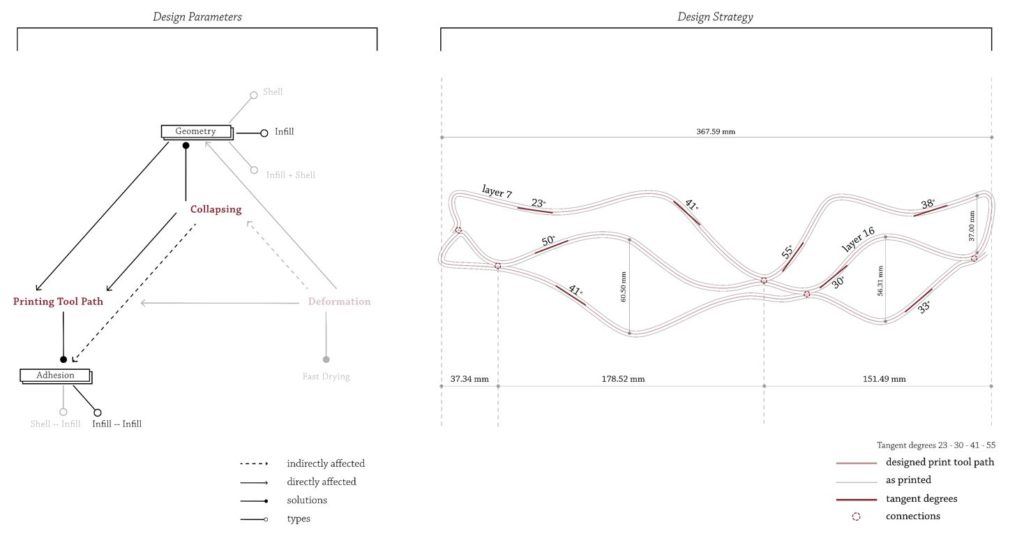
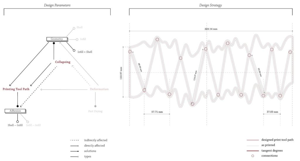
Different tangent degrees ranging from 23 to 55 were explored. The ranges toolpath can go before introducing a connection was tested as well. And greater range without connection points caused print to fail at an earlier layer such as left part of the print started failing at layer 7 while right side started failing at layer 16.
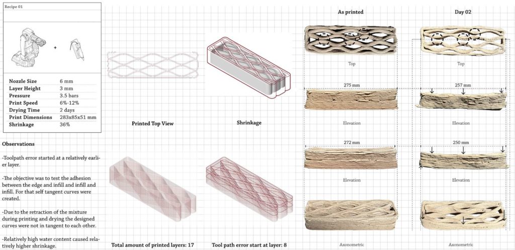
The objective was to test the adhesion between edge and the infill and infill and infill while keeping the tangent degree as a constant. Self tangent connection type was explored as well. Due to the retraction of the mixture during printing and drying this connection point separated (as can be seen in top view).
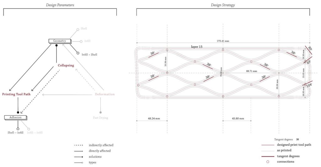
The tangent degrees were kept constant at 38 degrees and the amount of maximum connection points of a specific location was 3.
Shell and infill geometry was tested. Relatively less shrinkage was observed while deformation due to the inconsistent drying pattern was maximum. During printing as the mixture retracted over time self tangent curves were getting separated (as can be seen in the bottom close up pictures).
Adhesion between shell and infill were explored in convex and concave connection setup. Infill and shell adhesion worked the best on concave curve connections. The maximum distance each connection was 57 while minimum was 37.
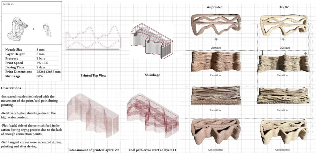
For this print the nozzle size was increased from 6 to 8 to assist with the movement of the printing tool path. During printing and even after drying flat (back) side of the print shifted its location, this caused unexpected deformation on the inside, making self tangent curves getting seperated.
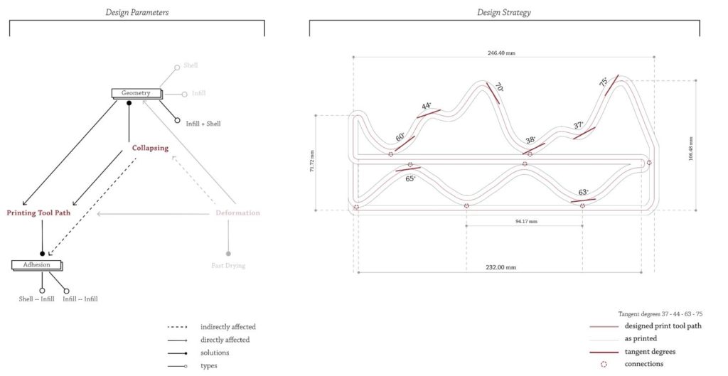
As two types of adhesion was explored, tangent degrees from 37 to 75 were tested as well.
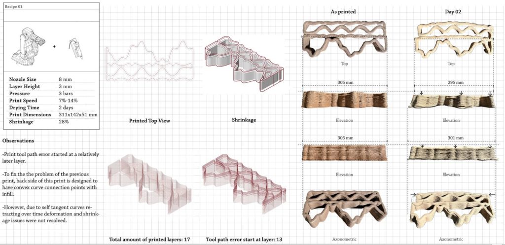
To fix the the problem of the previous print, back side of this print is designed to have convex curve connection points with infill. However, due to self tangent curves retracting over time deformation and shrinkage issues were not resolved.
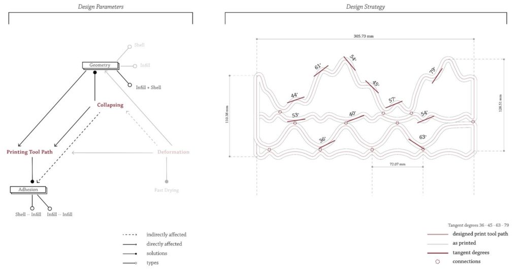
Tangent degrees from 36 to 79 were explored and the maximum distance between each horizontal connection was lowered to 79 (compared to 94 from the previous print).
Applications
01 – Tiles/Cladding
First type of application is tiles that have maximum surface area to be able to sequester carbon as much as possible by using the maximum amount of sawdust. Top to bottom approach will be followed, which is creating a global configuration first and dividing that into components.

Different dimensions for the tiles were determined after researching the industry standards.

First strategy is to create surfaces through collision/surface packing. Variables for these were curve length and the radius of initial circles. Although this strategy helps to increase the surface area it does not make a significant impact.
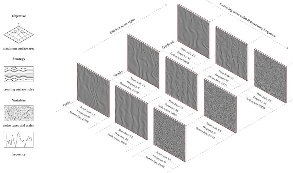
Next strategy is to create surface noises with different noise types, scales and frequency values. For this perlin and simplex noise was used and later on they are combined to increase the surface area further. This strategy had a much larger impact compared to before.

Last strategy was to create grooves with varied vertical divisions and z axis deformations. This way had the highest surface area values. That is why, the iteration which has vertical division value 150 while deformation in Z axis 0.5 was selected to be implemented to a case study.

Firstly, a facade that is 6 x 9 m with 12 windows was generated and then divided into small, medium, large components. 9 small, 97 medium and 45 large tiles are used. With this facade only 456 kg of sawdust can be saved from the landfills.
02 – Components for Improving Thermal Performance
Next application is components to improve thermal performance of existing buildings (to be used for rehabilitation of buildings). A bottom up approach will be followed, which is creating the individual components and aggregating them for the global configuration.

To improve the thermal performance, increasing the legth of the toolpath and bifurcation can be applied. The maximum number of branches and paths that energy travels within the print could cause a greater thermal lag and thus lesser conductivity.

Keeping these in mind initial set of toolpaths were created, ranging from increasing tool path length to focusing on bifurcation.

The print is divided into different blocks with specific performances. As the outer perimeter will be in contact with the exterior it could be optimized for external performance. Adding to that, there will be a part where this heat will be branched out and led to the inner perimeter.

From those inferences the catalogue was updated and different modules were created. There are 2 types of modules. Corner modules which will be placed around the contact of the windows and the edge of the facade to give a clean finishing. And regular modules to be placed in between. In regular modules, to increase the toolpath length and create alterations on the facade different iterations were tested on the outer perimeter.

Here is an exemplary aggregation. Corner modules will be 300 mm x 150 mm and regular modules are 600 mm x 150 mm. The close ups indicate corner module finishing, how 2 consecutive modules will be connected and how will one regular and one corner module be connected.

Using the same randomly generated facade, corner modules were placed and then regular modules were added. In this version 150 corner and 161 regular modules were used. However as this is a bottom up approach the placement of the components are not defined and different iterations can be created. And for this facade alone more than 2 tonnes of sawdust can be saved from the landfills.
In the next term, the design and global configuration of each application will be closely studied and experimented to create a large scale prototype.
