During the Introduction to Digital Fabrication course, we aimed to understand the methods of programming 3D Printing, CNC Milling and Laser Cutting machines. To learn the fundamentals of digital fabrication process, we had a certain amount of time for each method. Within the scope of the task, we wanted to get a grip on the limitations of each machine and to optimise the parameters according to the complexity of our designs.
Content
- 3D Printing
- CNC Milling
- Laser Cutting
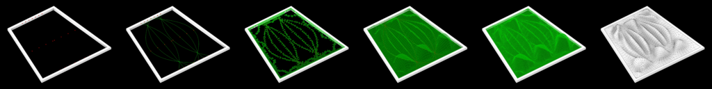
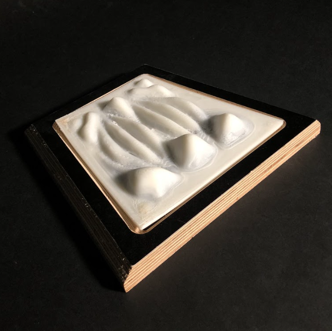
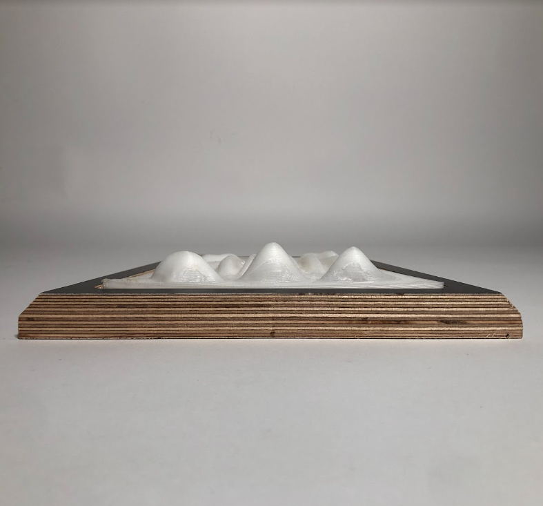
Exercise 1 – 3D Printing – Light & Shadow
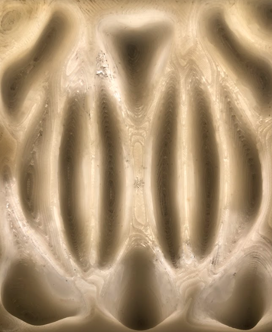
For the 3D Printing exercise our task was to design inside a trapezoid frame which would be a single component of the whole. We wanted to come up with an approach which tested the material and the machine. Therefore, we took translucency as the main focus of our design. Our idea was to create different thicknesses at a changing variety of heights to control light transition.
Design Process
- Fibonacci sequence
- Connect the lines
- Naked edges closest points
- Anchor and use Kangaroo
- Remesh
- Final model
Parameters
- Estimated print time: 6h 17m
- Printer: Zortrax M200
- Material: Z-ABS
- Nozzle diameter: 0.4 mm
- Layer: 0.39 mm
- Quality: Normal
- Infill: 15%
- Raft: Enable
Exercise 2 – CNC Milling – Truncated Pyramids
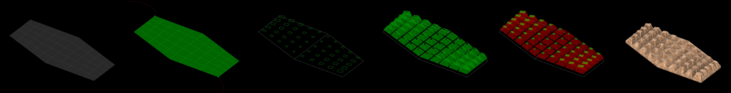
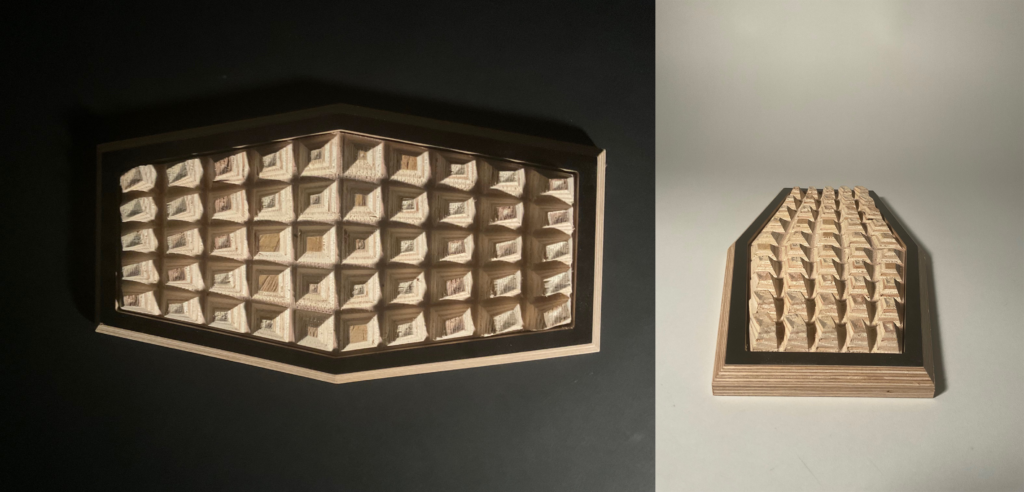
In the CNC Milling method, our goal was to create a shadow pattern which would iterate through the surface of a facade. We wanted to create a module which could be added one after another. First we divided our geometry to a 5×10 distorted grid, each rectangular geometry formed and acted to be the base of our pyramids. Then every pyramid is truncated in differentiating heights.
Design Process
- Surface divide
- Attractor points
- Scale, rotate and vertical move
- Loft
- Morphed caps
- Final model
Parameters
To form a complex geometry, we used RhinoCAM to program the different steps of the milling.
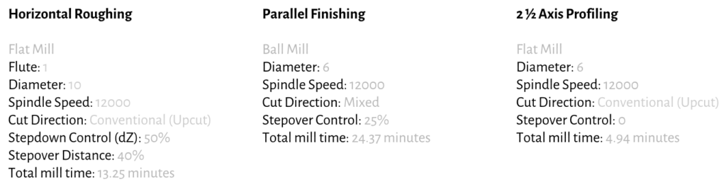
Workpiece Volume: 360x180x30mm
CNC Machine: ShopBot ATC PRS Alpha
Materials: Plywood 30mm thick; Black MDF 10mm thick
Post Processor: ShopBot_MTC
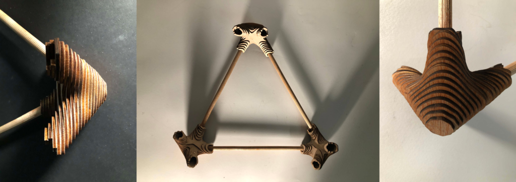
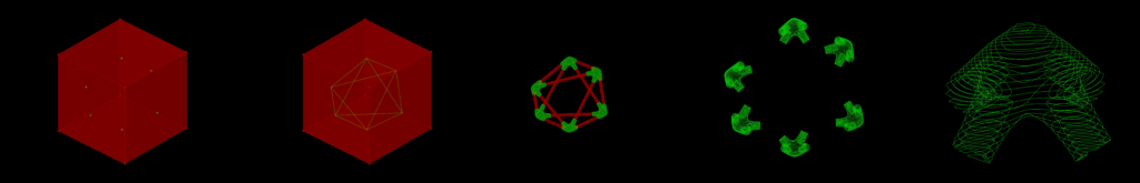
Exercise 3 – Laser Cutting – Adjustable Joint
In our final week, we got to use the Laser Cutting machine to form spatial joint with the technique that was assigned to us, Slicing/Stacking. We formed a triangular extending geometry in three axis which had joints in the corners. Every joint component is adjusted accordingly with a particular connection angle. For the prototype we split three joint components of our model into layers to use as the machine-readable file.

Design Process
- Movable points on different faces of the bounding box
- Connect the lines
- Curve domain and multipipe
- Contours of the joints
- Detail of a joint
Technique: Slicing/Stacking
Machine: Rayjet 500 (Bed size: 1300x900mm; CO2 lasers)
Materials: Plywood 600x1000x4mm; Rounded Sticks
Time: 40+ minutes