Using two primary sensors and actuators, a flood control system could be composed. The project’s intentions is to use water levels rising towards an ultrasonic sensor in order to initiate a servo motor that would essentially redirect water towards the soil moisture sensor thus activate a visual output ( a warning per se) through an LED if certain values are surpassed…
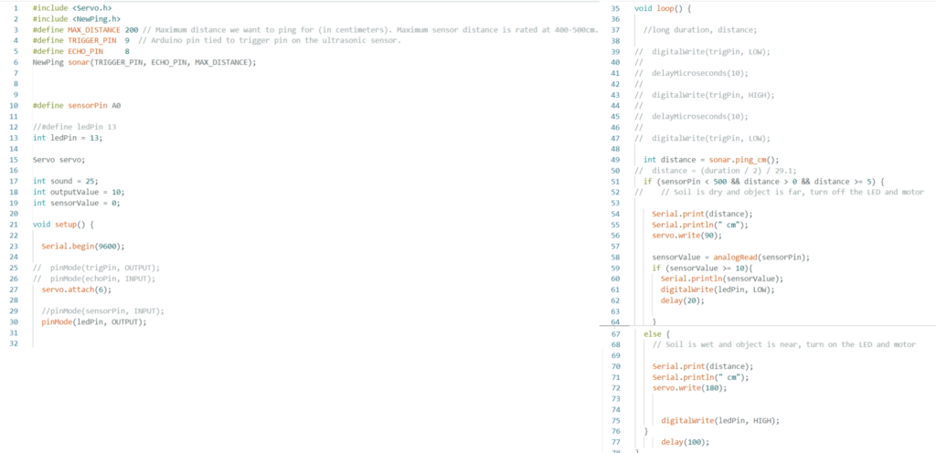
Pseudo-Code

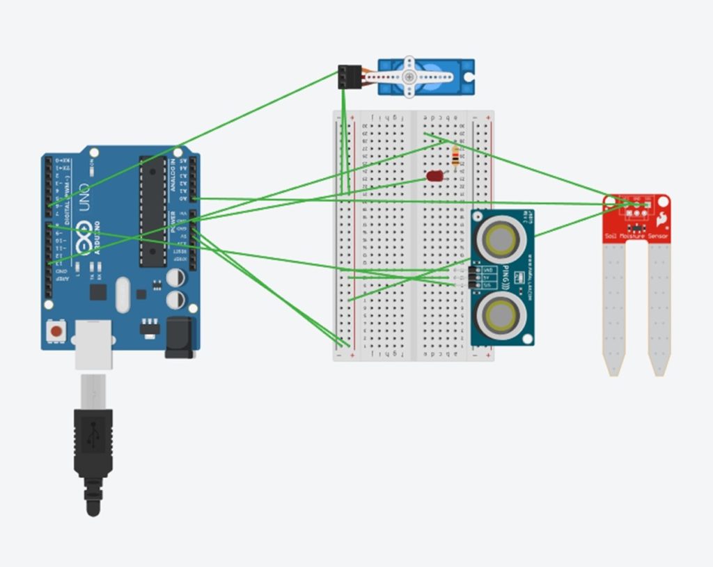
Bill of Materials


- A: Ultrasonic distance sensor
- B: Soil moisture sensor
- C: Breadboard
- D: Arduino Uno R3
- E: 220 OHM resistor
- F:Servo Motor (positional)
- G:LED (red)
Composition
Code
Final performance
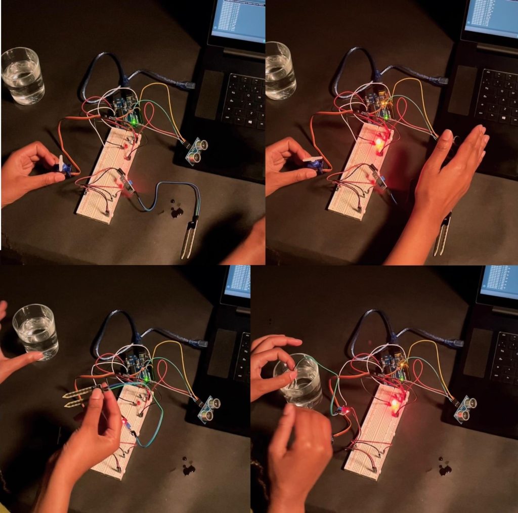
Prototype Video
Next steps
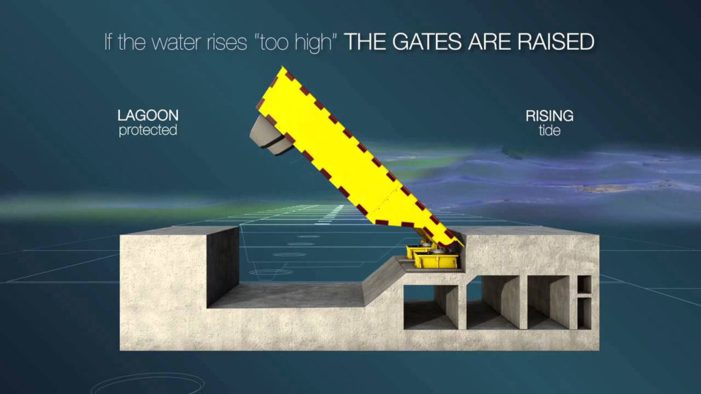
An automated flood barrier and warning system can be created using the methodologies explored above. As exemplified by the MOSE project ( a flood barrier system designed to protect Venice from extreme floods); a similar technique could be applied within areas that are negatively affected by unanticipated water levels.
source: Venice’s Mose flood barrier
https://pixels.com/featured/venices-mose-flood-barrier-paul-woottonscience-photo-library.html