
In order to familiarize and introduce us to different types of machinery tools and techniques, our studio was divided to three weeks of learning and exploring different machines related to different forms of digital fabrication. Each week we learned how to design and execute our model on different software related to the fabrication typology. This way we could asses the merits and limitations for each fabrication machine and explore there various techniques at the same time.
W-O1//
W-O1//The main objective of the assignment was to make a modular facade panel using different CNC machine. We needed to use a combination of different techniques while using the Rhino CAM software (i.e. Rhino Plug-in) for CNC milling, as a part our technique exploration part of the exercise.
W-O1.1// THE PROCESS
Material : Plywood I Machine : CNC Milling I Post Processor : ShopBot_MTC I Workpiece volume : 200 x 380 x 30 mm
The design was done in Rhino 7.0 and later with the help of the Rhino plug-in called Rhino CAM, it was translated to the format needed by the CNC machine to execute. Following are the steps in which final finish of the panel was achieved :
| RHINOCAM PREVIEW |
- HORIZONTAL ROUGHING
- Flute: 2
- Flat Mill
- Diameter: 10
- Spindle Speed: 12000
- Cut Direction
- Up-cut
- Stepdown Control (dZ): 50%
- Stepover Distance: 75%
- Time: 5.63 minutes
- PARALLEL FINISHING
- Ball Mill
- Diameter: 6
- Spindle Speed: 12000
- Cut Direction
- Up-cut
- Stepover Control: 15%
- Time : 51.91 minutes
- Ball Mill
- ENGRAVING
- Flat Mill
- Diameter: 4
- Spindle Speed: 12000
- Cut Direction
- Up-cut
- Total Cut Depth: 3 mm
- Time : 9.63 minutes
- Flat Mill
- PROFILING
- Flat Mill
- Diameter: 6
- Cut Direction
- Up-cut
- Total Cut Depth: 25 mm
- Flat Mill
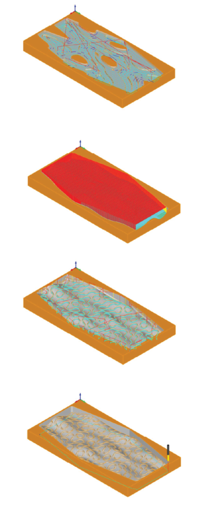
W-O1.2// DESIGN AGGREGATION
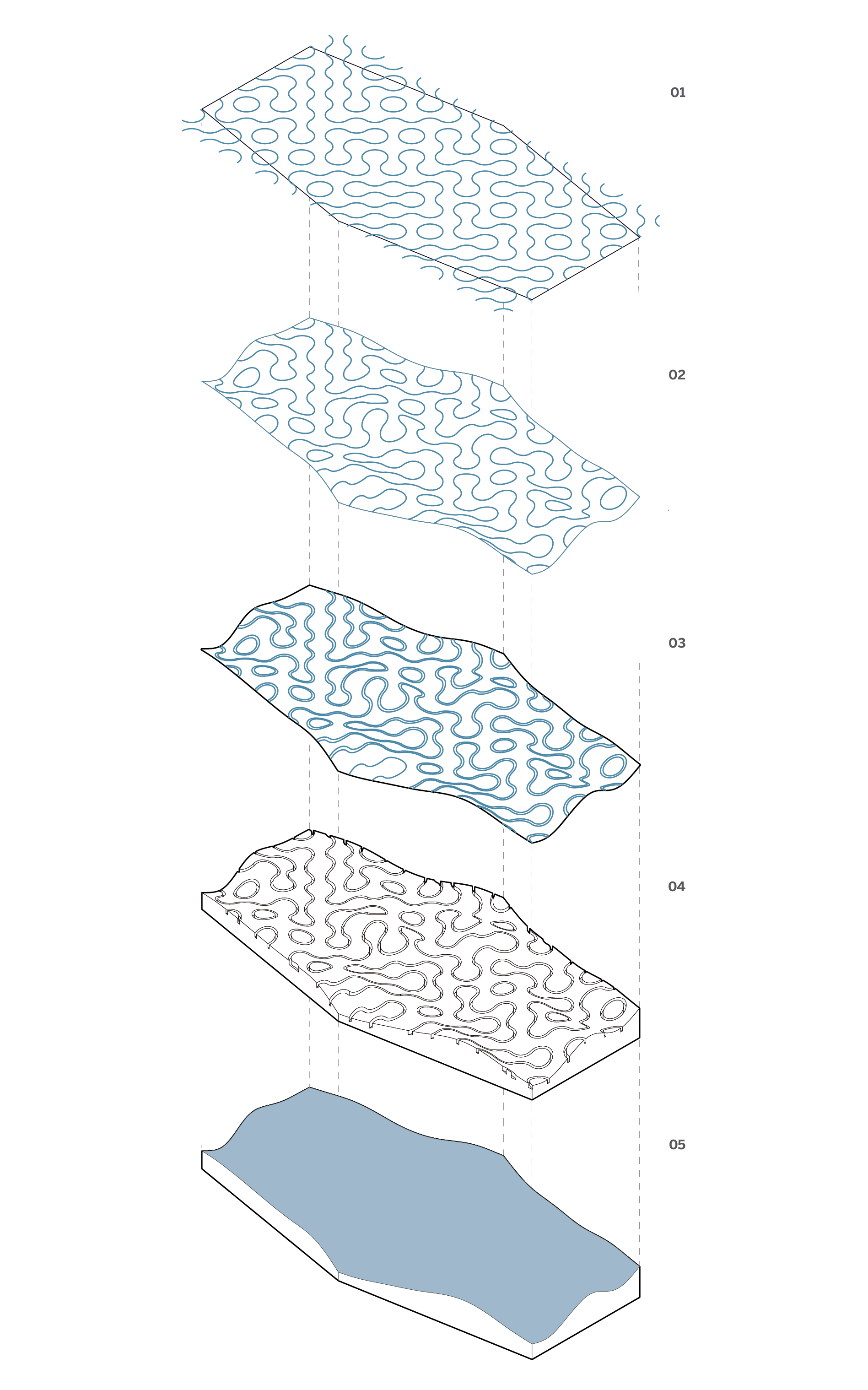
LEGEND
01. Engraving with a 4mm Flat bit
02. Generating Pattern
03. Projecting Pattern
04. Final Model
05. Terrain Development
W-O1.3// FINAL RESULTS
The aim was to utilize as many different types of techniques to make the panel, thus the end product was an undulated surface with the Truchet tile design engraved over it. The plywood layers added to the texture of the surface and engraving creating a light and shadow contrast on it.
W-O1.4// PROBLEMS FACED
We used an up-cut bit for the engraving, which caused the plywood to splinter at the surface on the engrave. The bit force the material upwards thus creating the splinters and had to be sanded down , which was extensively time and labor intensive. The profiling part of the execution was set with a higher depth, which affected the finishing quality of the modular panel.
W-O2//
W-O2//The main objective of the assignment was to make a interlocking joint using the laser cutting machine. The material we could use was plywood, MDF, or acrylic of varying thickness.
W-O2.1// CUTTING PROCESS
Material : acryllic – 3 mm I Machine : raylet500 I technique : interlocking I joint : simplified “yamato wooden puzzle”
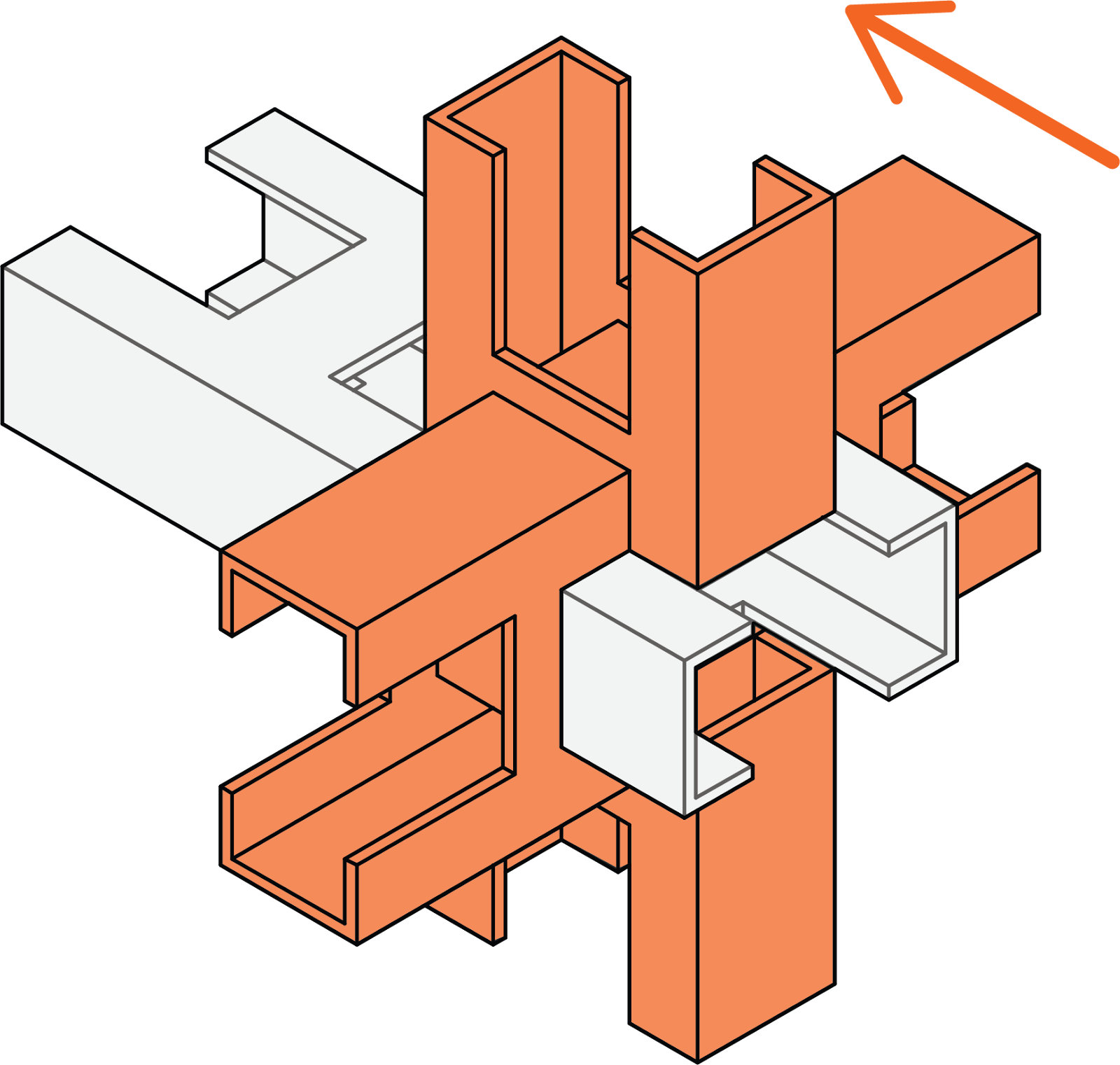
The reference for the joint design was the interlocking wooden cross puzzle – “Yamato Block Puzzle”. This joint interlocked three wooden members in X,Y and Z-axis, without any nails or bolts. Limited by the availability of materials and the characteristics of the available material, we modified the joint to be simple, flexible, and of higher structural strength. Using the finger joints mechanism we attached all the sides of all members of the joint. The new joinery allowed the wooden members to be in a series of continuity in X, Y, and Z directions and also retained the structural integrity of the joint. Also using acrylic as a material for the joint increases the structural strength.

Layer 1 (RED) was for the inner lines I Cut 1 Power: 50 Speed: 2.00 II Layer 2 (BLUE) for the outside lines I Cut 2 Power: 50 Speed: 2.00
W-O2.2// ASSEMBLY PROCESS

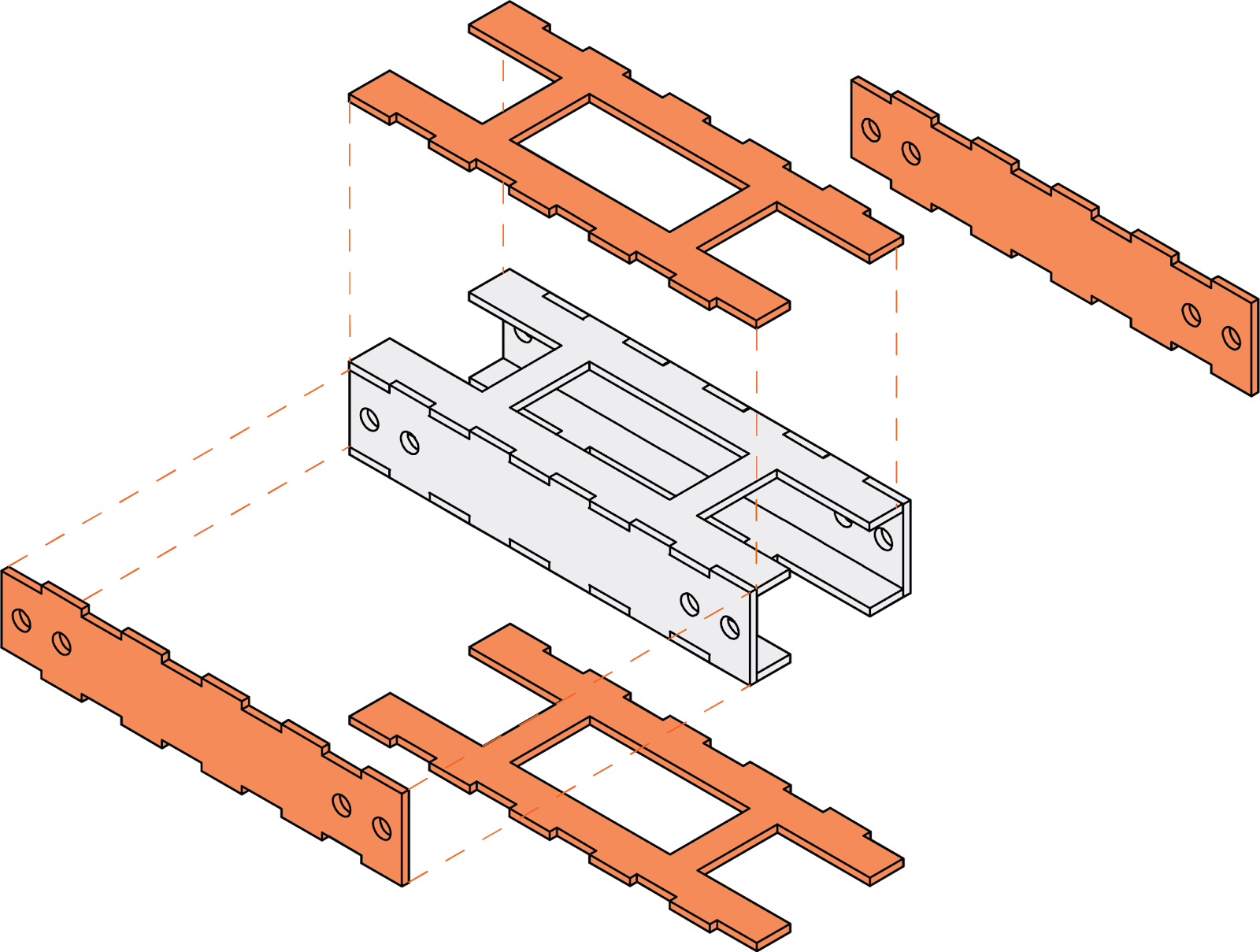

| MEMBERS 01, 02 AND 3 |
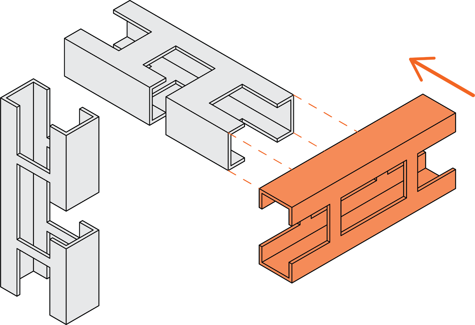


| STEP 01, 02, 03 AND 04 |


| ADDING THE STRUCTURAL MEMBERS TO JOIN |
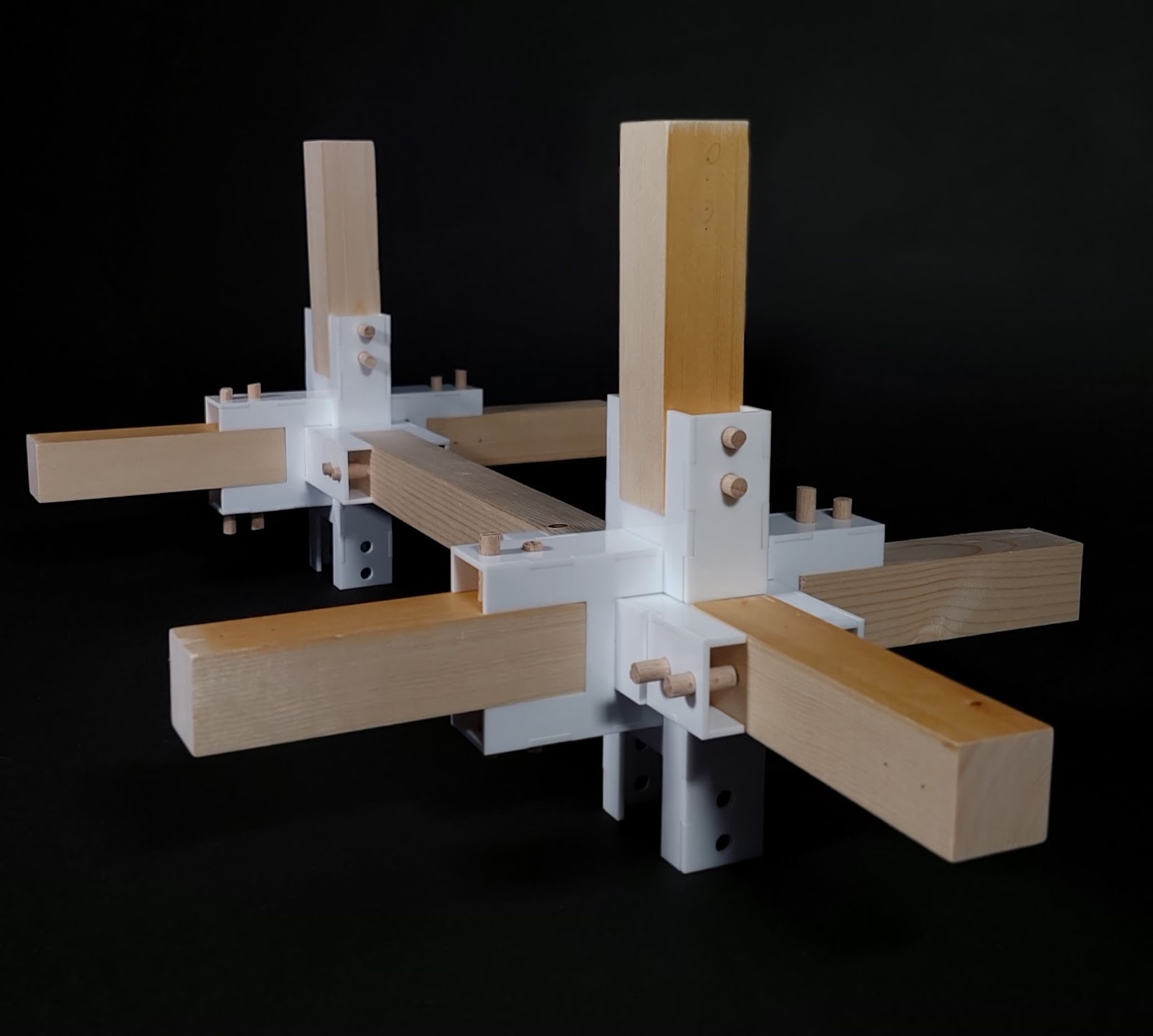
W-O2.3// FINAL RESULT
W-O2.3// PROBLEMS FACED
A few problems were faced during assembling such as:
- Acrylic is a fragile material and with the strength needed to put the pieces in place, some of the pieces broke and had to be laser cut again.
- Offset of borders for the finger joints required many trials, after which we found that 0.1mm was the correct offset for this acrylic.
- The chosen material for fixation in the wood was the cylindrical wooden sticks that had bigger diameter than holes made on the joints, it took a lot of sanding to get them into the right size. I The position of the holes was not standardized and it made it difficult to drill on and make the structure stable.
//3D PRINTING
W-O3//
W-O3//The main objective of the assignment was to 3D print a module for a facade which explores light/shade, texture, and sunlight protection.
W-O3.1// THE PROCESS
After designing the model on Rhino 7.0, the file was imported into Z-Suite Software to translate into the code read by the 3D printer.
Material : Z-ABS 2 I Machine : zortrax m200 I layer : 0.29 mm I infill : 90% I time : 5 h 51 min. I supports : no supports
W-O3.2// FINAL RESULT
The result was very satisfying considering the scale and lack of supports at the top. It can also be replicated in a facade and used with different levels of rotation to have different types of sunlight protection and wind resistance.


W-O3.3// PROBLEMS FACED
As the model goes up, the finishing of the printing loses quality, and the strings of the filament start to show. The speed of printing should’ve been slower to prevent that from happening. But since in our case it is just a prototype model, we conclude that it is better to have faster printing than a better quality of finishing.
