
The Digital Fabrication introductory course focused on the exploration of different fabrication processes and getting to know the logic behind Laser cutting, 3D Printing and CNC Milling. The main aim of the course was not only to familiarize one with the machines and the FabLab protocol, but also to learn to design with the capabilities and limitations of both material and machine in mind, as part of a continuous digital fabrication process culminating into a physical model. Our personal overarching approach to the task was to, at the risk of overstepping them, test the limits of each process in order to be able to work within them later on.
Laser cutting
How can we connect rigid beams with a folding mesh to create a flexible spatial joint?

The task was to make a three-dimensional connection between timber beams, utilizing the technique of folding. All parts must only be fabricated with the help of the lasercutting machine. Our design goal was to create a pattern that allows the structure to develop from a flat surface to a three-dimensional form that keeps its ability to expand and contract.
In nature the most common example of a similar folding technique are leaves. What sparked our interest was that leaves are self-folding, which means they adapt their geometry with their growth and can fold according to day-/nightcycles. That led us to create a prototype in an origami technique, since this method is similar to what we can observe in nature and in addition gives structure nonlinear mechanical properties.
Since folding works best with geometrical patterns, the grid was formed from hexagons. To connect beams two grid types were developed : 1. Plane with perforation for sticks 2. Folding with mesh divisions. The material of our choice was Polypropylene because of its capability to repeatetly fold and unfold again. For this to work, a symmetrical design was developed that was cut from both sides, precisely keeping in mind the kerfing and other inaccuracies of the lasercutting technique.
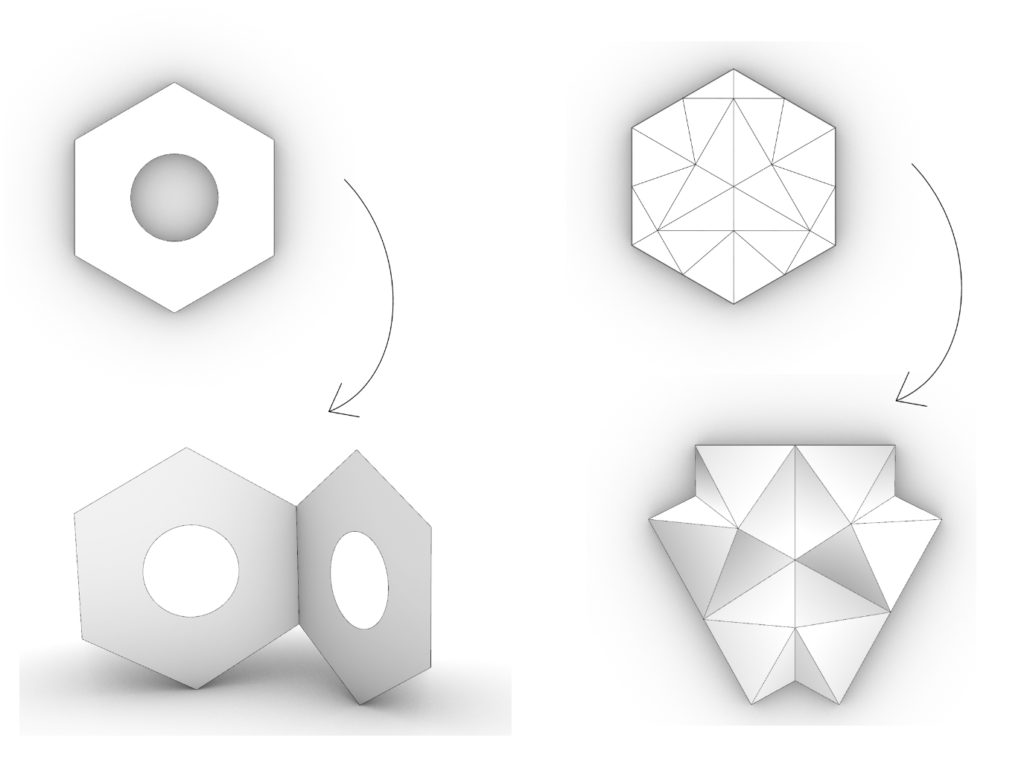
Digital exploration / cell folding
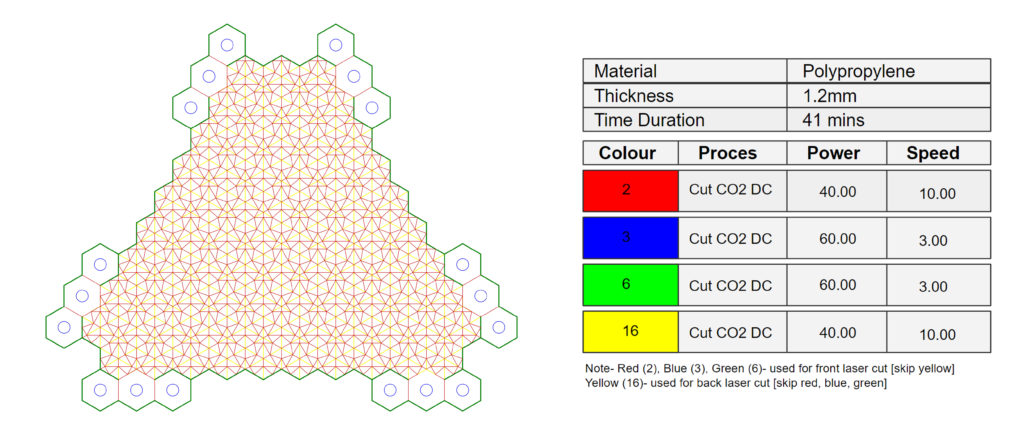
Subsequence:
Step One- Using red, blue and green layers and laser cutting the sheet.
Step Two- Flipping the sheet and securing it with tapes.
Step Three- Only using yellow layer to laser cut the back of the sheet.
Digital exploration of the folding structure
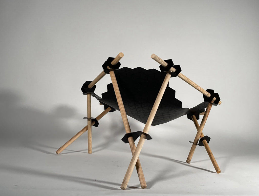
The aformentioned qualities of the design lead to the creation of a chair as end product, which combines all the benefits of the foding structure in an applicable way. The flexible construction capable of adapting to different positions, gently snuggling around the user with its geometrically sensual touch.
Observations:
- Polypropylene easily breaks, for folding more flexible material is required
- Pattern doesn’t work in a small scale
- Folding mesh supported by beams can create a multi-stable system
- Mesh can fold in different directions and can be flatten down again
Future steps:
- Test different materials
- Find appropriate grid cell size
- Improve stability
- Try different cutting speeds to find optimal cutting depth
- Complete folding mesh
3D printing
How can we optimize a fluent geometry to 3D-print it without supports?
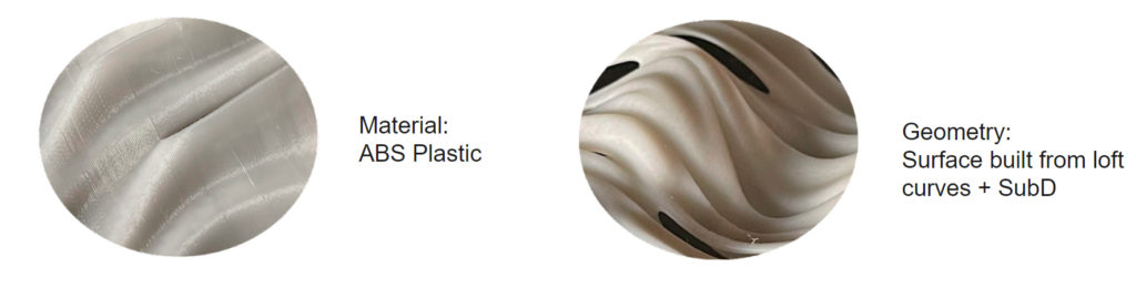
For the second week, we explored the process of 3D-Printing. The task was to design a shading device as part of a facade element. The grid structure was transformed into a sequence of undulating waves, varying in its amplitude in both x and y axis. This geometry gradually reached overhang angles on the limit of the printer’s capability to reproduce them without support – what was one of the keys to stay within the assigned time maximum of 8 print hours. Furthermore, the consequently cut holes that perforate the structure to let selected rays of light penetrate the facade added another layer of complexity, as their highest points were bridged by the printer, again without the use of supports.
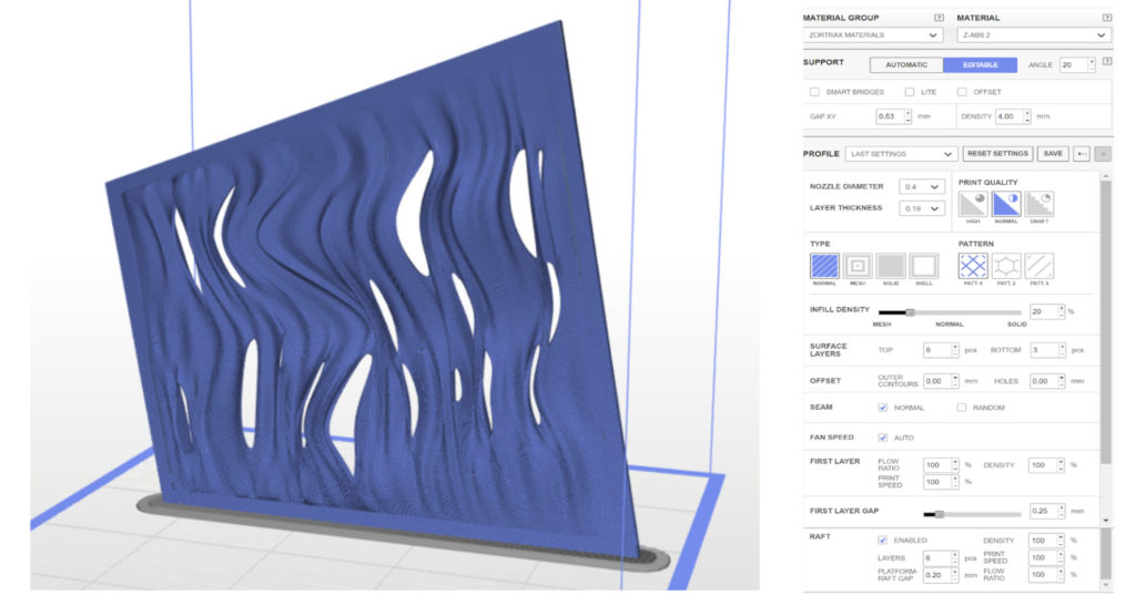
Settings and printing paramters
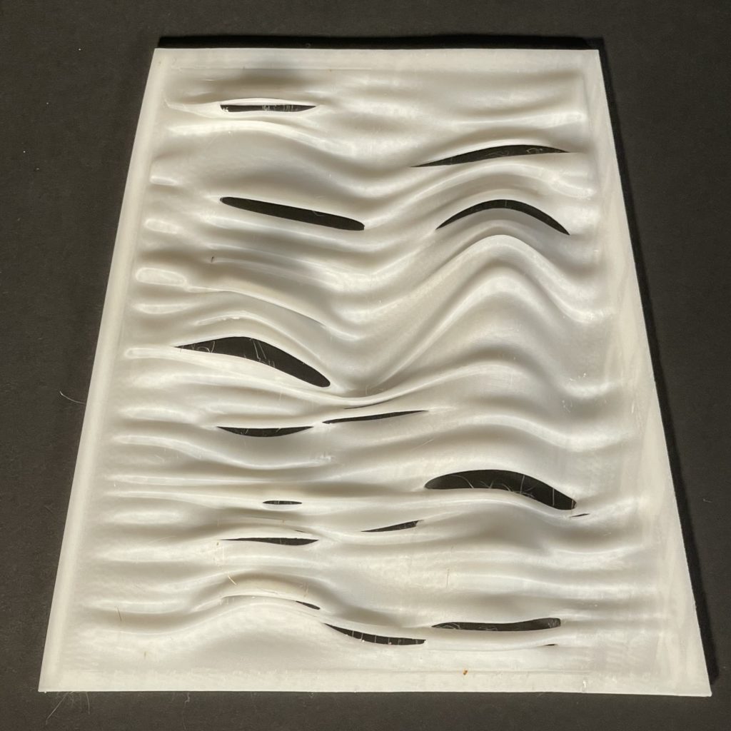
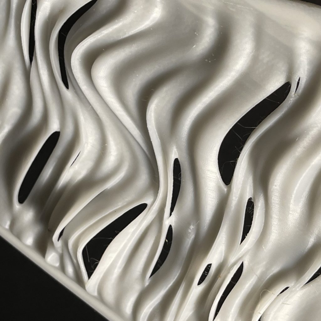
Final model
Shading test
CNC Milling
Can we achieve distinct surface patterns by using different finishing parameters?
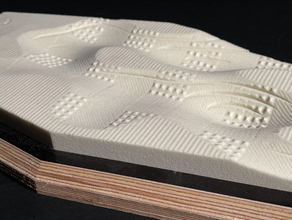
In the CNC Milling fabrication method, we explored the textures that can be achieved by different finishing techniques on the material provided. Our goal was, again, to work with the “flaws” of the machine, in this case the never perfectly smooth finishing surfaces. Our approach, to not see these as limitations but rather as opportunities and unique characteristics that we want to emphasize on, resulted in a variation of distinct surface patterns combined in one prototype with different transitions between them.
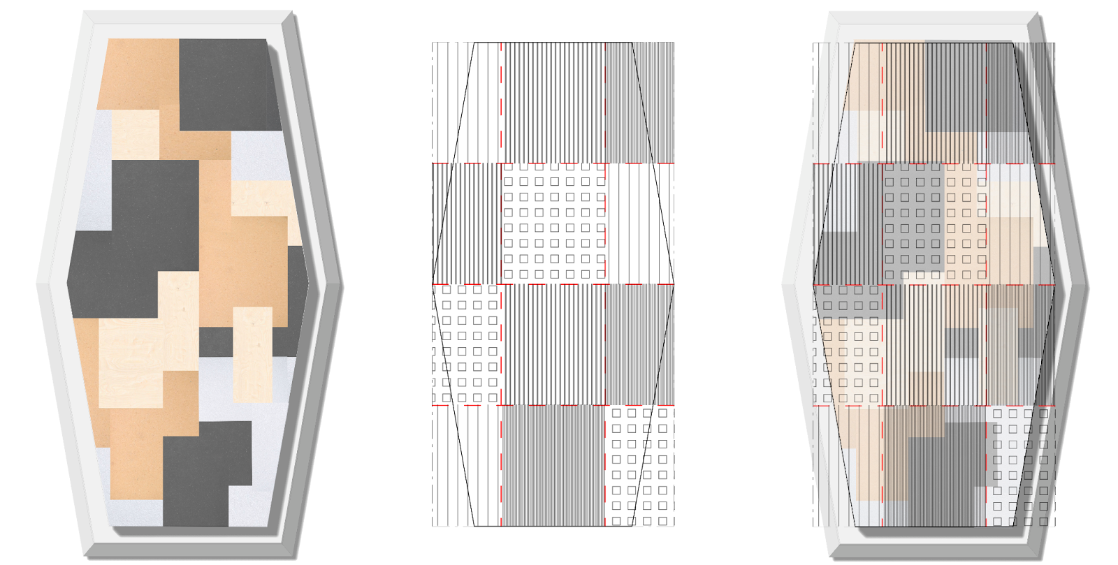
Initial concept
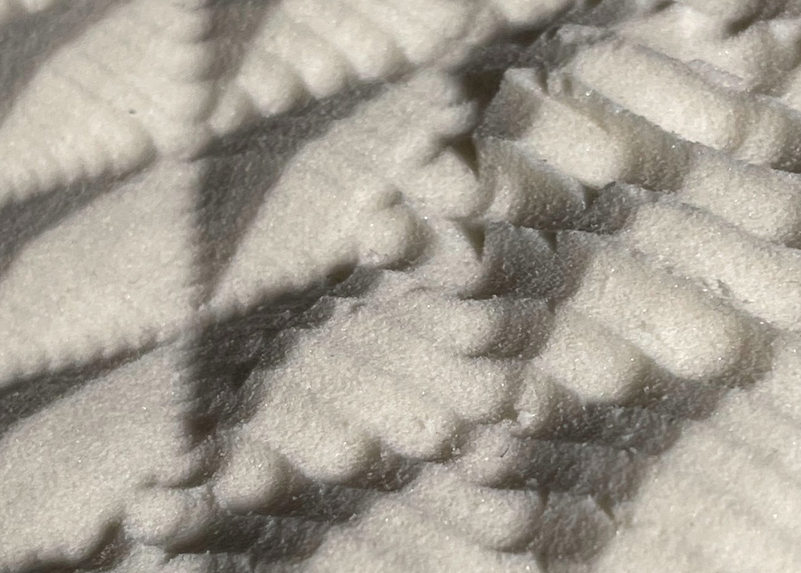
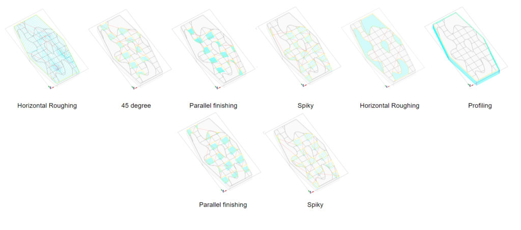
First test was made on PU foam block 10 x 5 x 5 cm. It was divided into 5 regions to each was applied different type of finishing.
For the final model we used following types of finishings: Parallel finishing, Spiky pattern and 45 degree finishing.
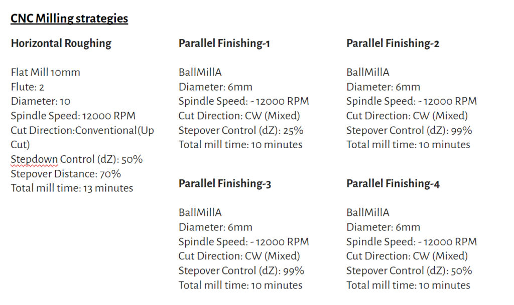
Material: PU Foam (40mm)
Machine: TRex-S01215
Workpiece volume: 150x150x30mm
