
Back to the Future– A circular construction prototype using gathered wood elements.
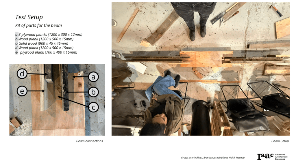
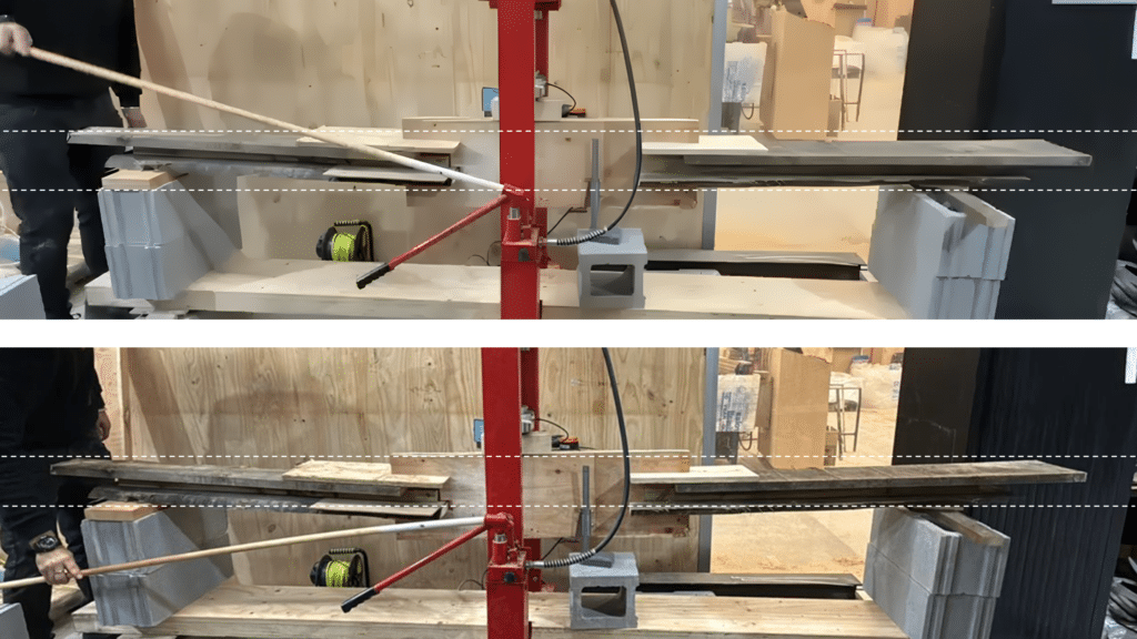
Test Setup
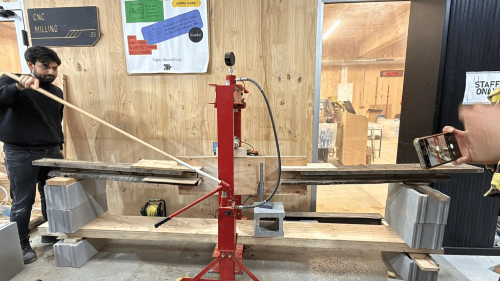
Type of load
The test was setup to handle a single point load. The beam was raised on top of 2 concrete blocks and load applied to the center.
Interlocking and Stacking– The Interlocking joinery was conceptualized along with stacking where the bottom interlocked component ran deeper in the beam to accommodate tension force.
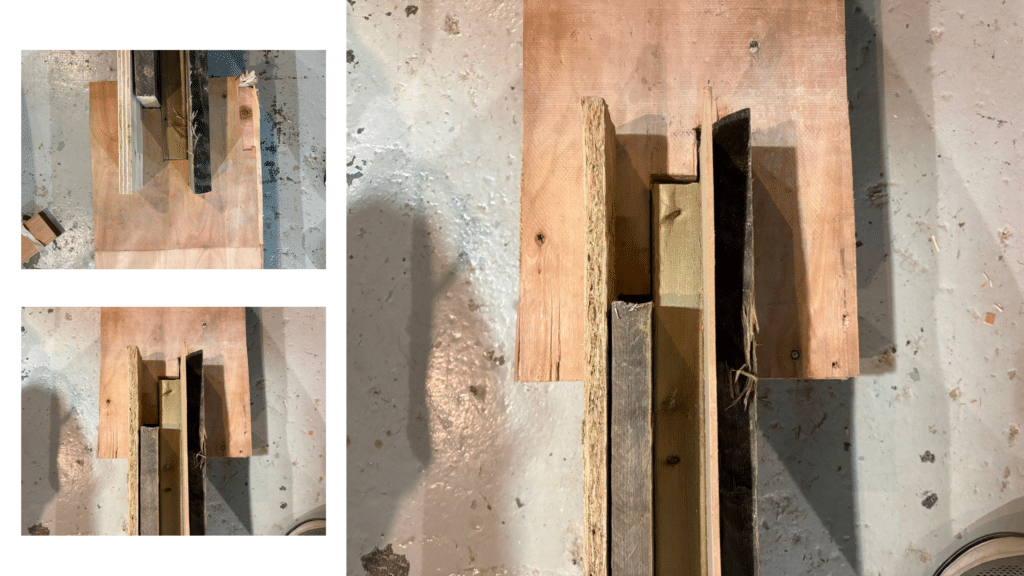
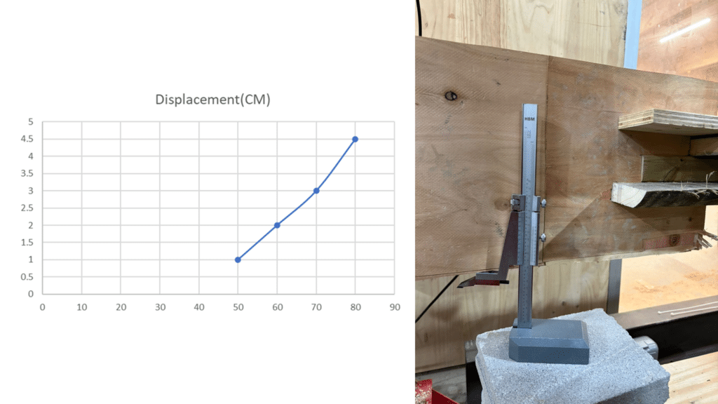
Beam Deformation
One mechanism of failure was encountered in the vertical portion of the beam. We discovered that the vertical members did not have sufficient connections between them causing them to act as individual members rather than one continuous vertical member resulting in buckling from torsion. This weakness become apparent at 40 kg of applied weight.
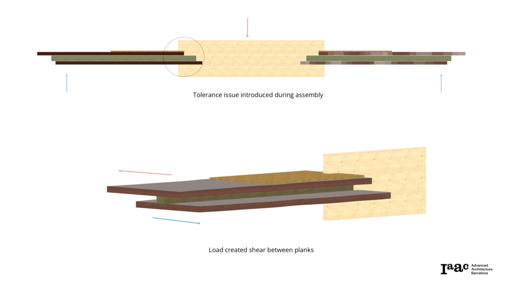
During testing, we also found that there was an error in tolerances introduced during assembly. Stacked horizontal members were not fit precisely into their join before connection, preventing the beam from supporting as much weight as the design should have theoretically withstood. Failure occurred at 82 kg of applied weight.
From this deformation graph, we can see that the beam behaves inconsistently from what would be expected due to the factors previously mentioned. What we could expect to see when these problems are resolved is the greatest deformation to be seen at low levels of weight application with the beam then stabilizing and withstanding increasing loads without further deformation.
Point Load
The test was setup to handle a single point load. The beam was raised on top of 2 concrete blocks and load applied to the center.
In reviewing our test, we noticed that the beam was placed slightly off center, resulting in the load being placed closer to the joint that contained tolerance issues, further exacerbating the weakness and resulting in premature failure.
Beam Deformation
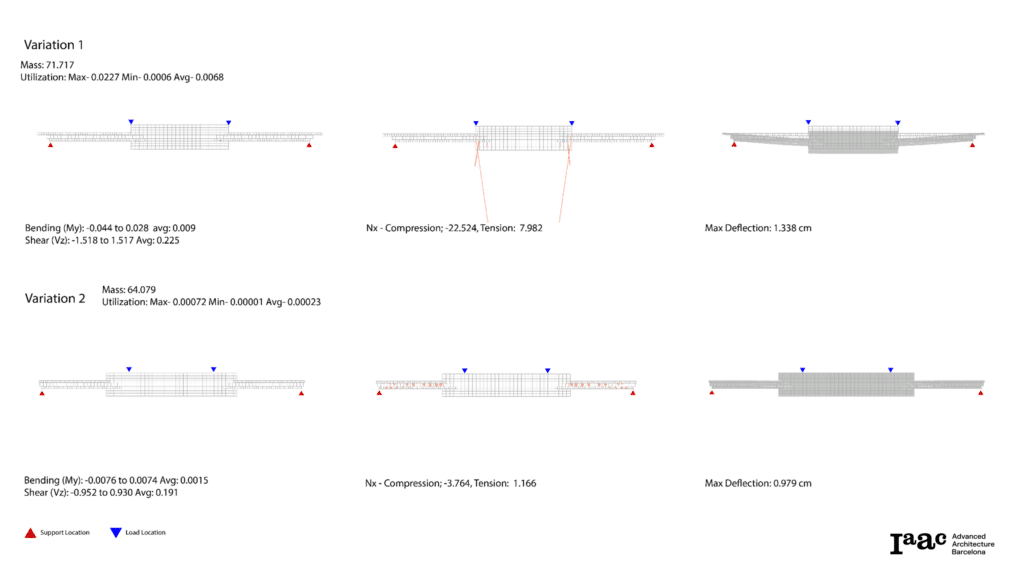
One failure point of the physical model was insufficient attachment between vertical members. This caused the members to act individually instead of as a continuous member as digitally analyzed, resulting in failure beginning at 40 kg of applied weight , whereas karamba analysis showed the total load bearing capacity of greater than 1000 kgs .
This failure could be prevented by securing the vertical members together with the introduction of dowels allowing them to function as a continuous member and preventing buckling of individual members.
Additionally, the weakness of the joint that lead to total beam failure at 83 kg could be avoided by more precise assembly of components. By fitting the joints tightly together before securing, the horizontal stack would not separate under tension as occurred during manual testing. This would result in dramatically improved performance.
Wood Waste Circular System
Feedback Loop System (Closed Loop Design)
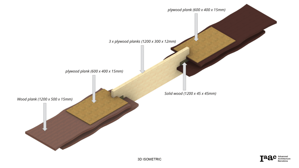
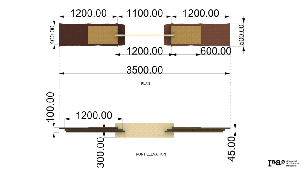
Interlocking Beam
The beam typology operates as a layered timber composite, where waste plywood and reclaimed timber are structurally reintegrated into a hybrid section. The system transforms wood waste into an active structural member, merging material reuse with structural performance.
This creates a circular timber system, where offcuts and reclaimed boards are re-integrated into structural members, reducing virgin timber use and extending the material lifecycle.
Structural benefits :
- Layered waste cuts function together as continuous beam
- Smaller pieces reduce defects and cracking
- Redundancy improves failure safety
Environmental benefits :
Structural benefits :
- Layered waste cuts function together as continuous beam
- Smaller pieces reduce defects and cracking
- Redundancy improves failure safety
Environmental benefits :
- Reduces virgin timber extraction
- Reduces landfill
- Stores carbon longer (carbon sequestration)
- Supports circular economy architecture
