In the Introduction to Digital Fabrication we were required to explore and investigate 3 different manufacturing processes which consisted of using a Laser Cutter, a 3D Printer and a CNC Milling machine. In the laser cutting exercise we looked at how to form a 3D spatial joint from 2D laser cut pieces. Essentially figuring out a puzzle. The 3D printing exercise was looking for us to push the limits of additive manufacturing by creating a shading facade. And finally the CNC Milling class wanted us to explore the subtractive side of manufacturing by designing a surface skin where we tested the limitations of what the machine was able to do.
Digital Fabrication: Laser Cutting
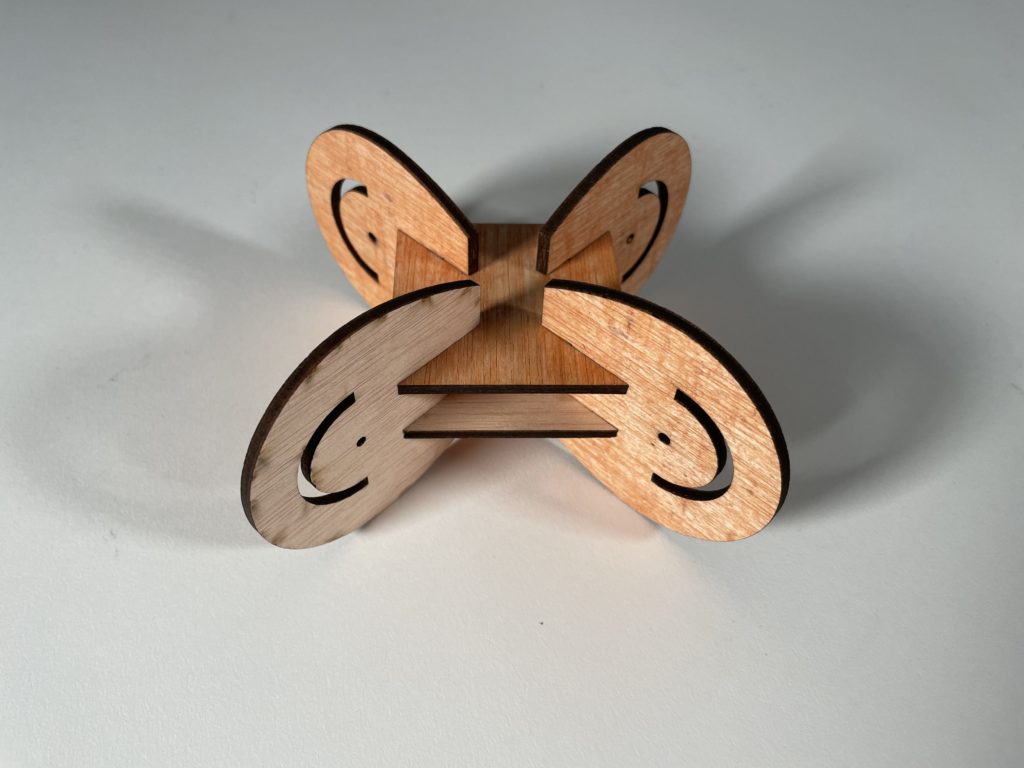
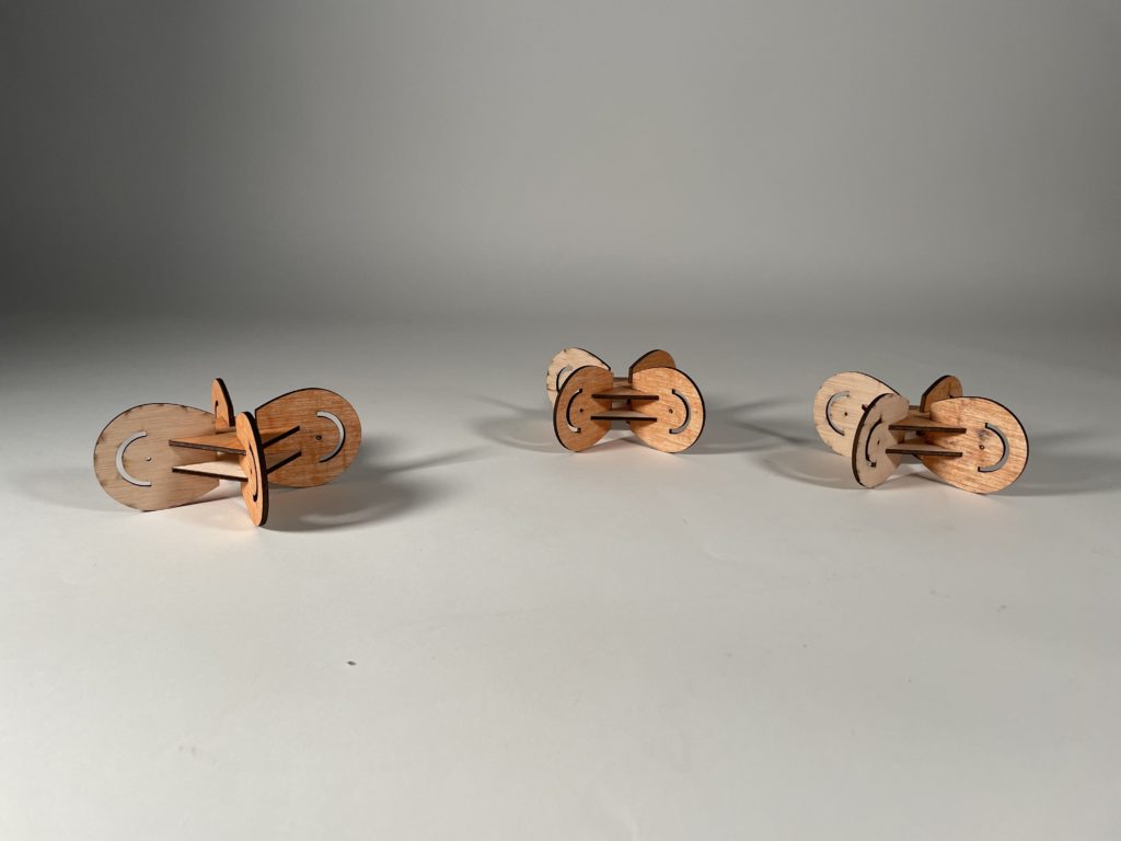
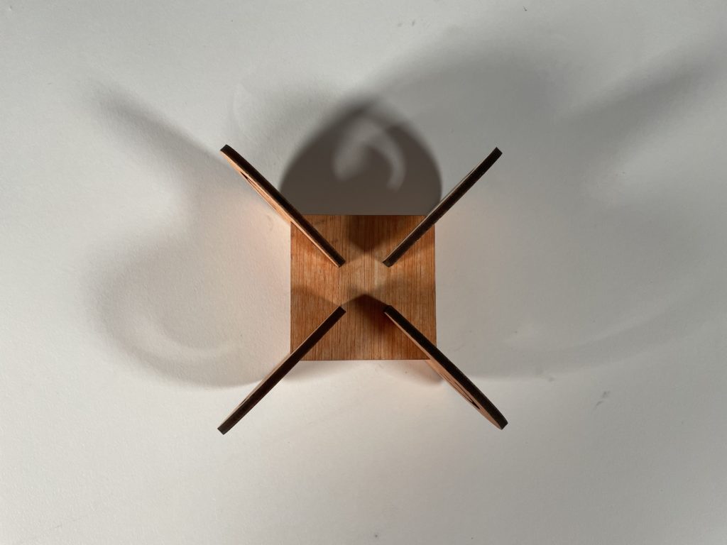
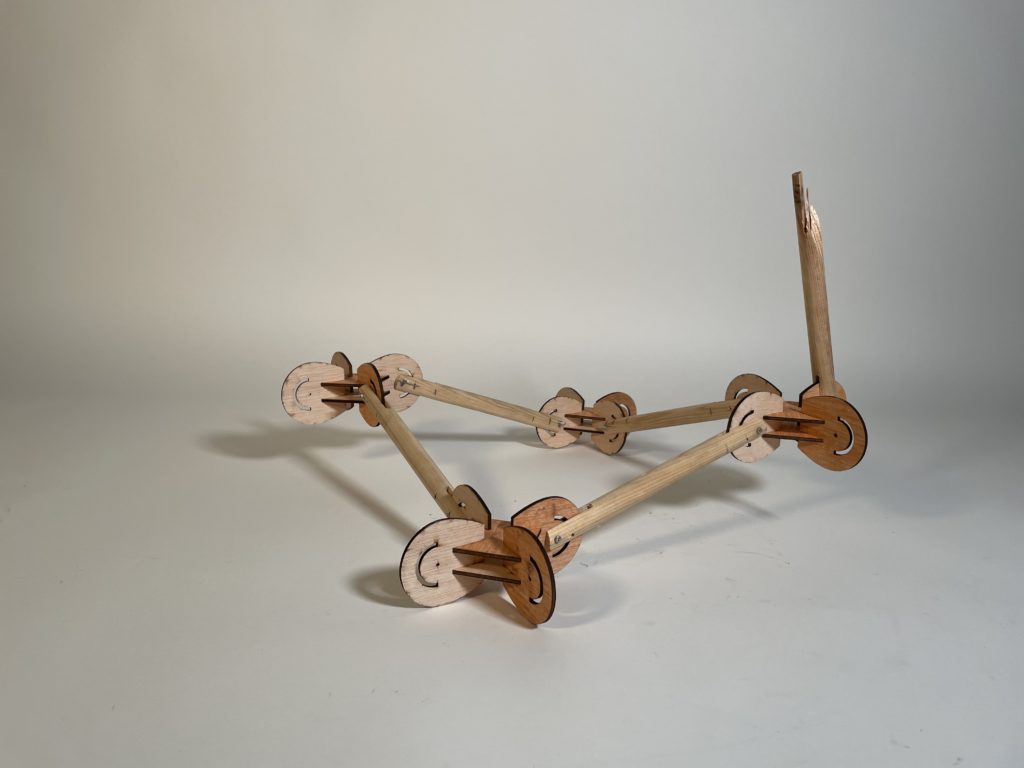
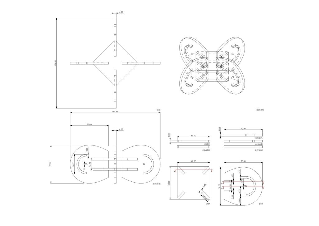
Interlocking Joints was the method given to us. The final design came about after a long process of trial and error with the first two designs. We tried to combine the best of what we had learned with interlocking and apply it accordingly. What came about was a strong rigid simple interlocking system made of plywood that tested the tolerances of the pieces. The joints were designed with kinetic ends in mind that would allow the additional wooden rods to move at a maximum of 180 degrees. This would allow for an assortment of systems and connectivity between spatial joints, from simple to something a bit more complex.
Parameters:
Material: Plywood, due to its strength, 4mm.
Technique: Laser cutting
Joint type: Interlocking
Machine: Rayjet 500; bed size 1300x900mm (CO2)
Working Parameters:
Layer 1 was for the inner lines and layer 2 for the outside lines.
Layer 1 = cut 1 Laser 2 = cut 2
Power: 45,5 Power: 45,5
Speed: 1,80 Speed: 1,80
Time management:
Final cutting: Complete design, lasted 14;16 minutes.
Digital Fabrication: 3D Printing
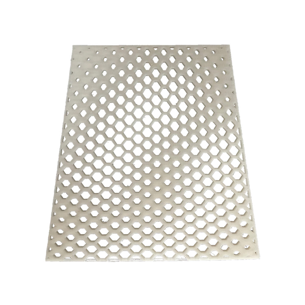
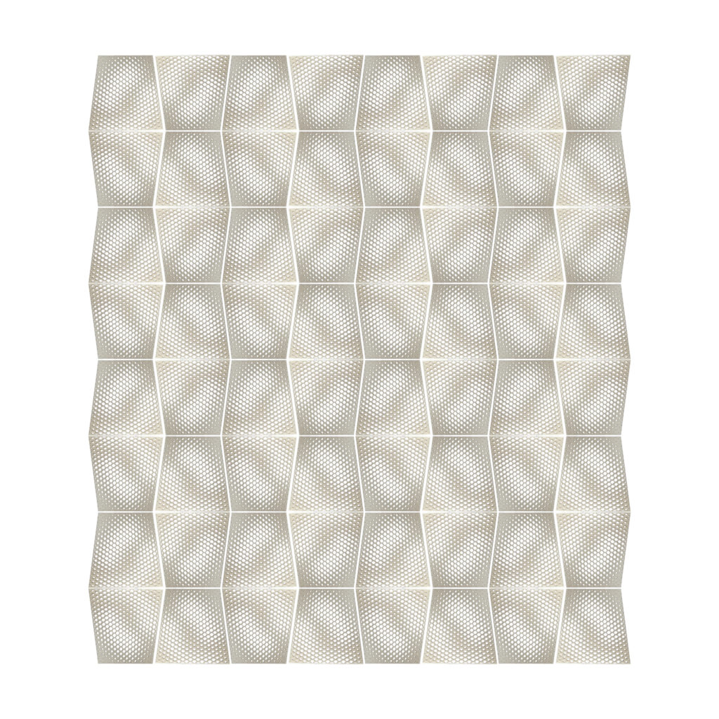
We started off with a waveform made in Rhino for experimentation. We did not receive the required results with this because it ended up printing with a lot of supports. For our main prototype we produced some sketches and from the sketches we proceeded to use grasshopper to bring our idea to reality. The hexagonal shape became the dominant one as the design progressed. It is a shape that is used in a honeycomb as it is strong and able to stand forces from multiple directions. Our prototype was printed vertically as we would not need any supports apart from the rafters when printing.
Parameters(Test):
Material: ABS
Technique: 3D Printing
Machine: Ultimaker Cura
Procedure:
- Save the Rhino file in “.stl” format.
- Open this file in Ultimaker Cura.
- Go to “Advanced” Print Settings.
- Fast Print – 0.2mm Layer Thickness
- Infill – 20%
- Support was automatically created in this software.
- Material used was ABS.
- Scale of the model printed was 1:1 of the Rhino Model.
- Finally “Sliced” the model to then preview it.
- Time taken to print this prototype was 50 mins.
Parameters(Final):
Material: ABS
Technique: 3D Printing
Machine: Zortax M200
Procedure:
- Save the Rhino file in “.stl” format.
- Open this file in Z-Suite.
- Go to “Advanced” Print Settings.
- Layer Thickness – 0.19mm
- Infill – 50%
- Quality – High
- Material used was ABS.
- 6m Raft Layers.
- Scale of the model printed was 1:1 of the Rhino Model.
- Finally “Sliced” the model to then preview it.
- Which printer?
- Time taken to print this prototype was 50 mins.
Time for printing: 6h 54min
Material usage: 34g

Digital Fabrication: CNC Milling
For the prototype we wanted to experiment with the curves and with how steep and deep we could go while milling. We also added squares to discover how the machine dealt with ‘suddenly’ adding height difference on the Z axis. After making the prototype, we used our reference verses a rhinoceros 6 file in which we created different curves with different depth, steepness and shapes. Based on the research, we eventually arrived at our final model.
Parameters:
Material: Plywood 30 mm.
Machine: CNC milling
Post Processor: ShopBot_MTC
Workpiece volume: 360150x30mm
Engraving:
Flat Mill
Diameter: 10mm
Spindle Speed: 12.000 PRM
Cut Direction: Up Cut
Total mill time: 0.23min
Horizontal Roughing:
Flat Mill
Flute: 1
Diameter: 10mm
Spindle Speed: 12.000 PRM
Cut Direction: Upcut
Step Down Control (dZ): 50%
Stepover Distance: 40%
Total mill time: 18.51min
Parallel Finishing:
Ball Mill
Flute: 2
Diameter: 6mm
Spindle Speed: 12.000 RPM
Cut Direction: Mixed
Stepover Control: 25%
Total mill time: 19.46min
½ Axis Profiling:
Flat Mill
Flute: 2
Diameter: 6mm
Spindle Speed: 12.000 RPM
Cut Direction: Upcut
Total mill time: 4.97min