
03.10.2022-21.10.2022
Laser Cutting
03.10-07.10
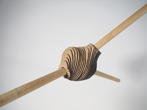
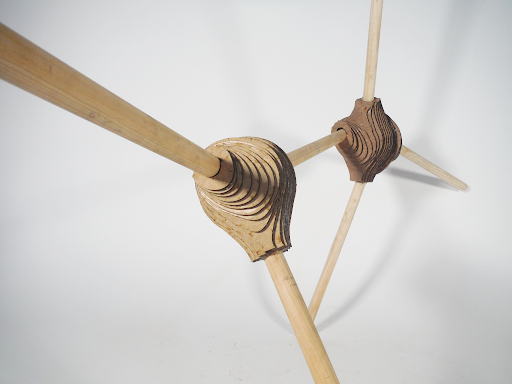
Exploring the Fabrication Parameters of Spatial Joint

Utilising the inherent property of trees
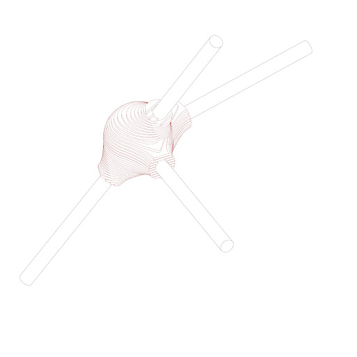
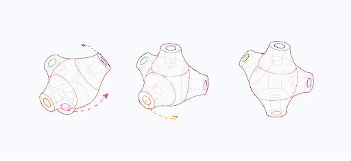
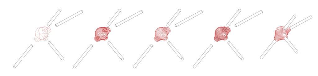
The main inspiration behind the concept for this spatial timber joint is ‘edaphoecotropism’ which is a natural process of trees incorporating foreign objects into themselves. When a foreign object is in the way or obstructing the growth of a tree, “the living tissues of the tree itself simply flows around the object and engulfs it and in doing so, the tree binds itself to the object and the connection actually becomes stronger as time passes.”1 And also the fact that in a way, trees themselves are basically stacks of concentric tubes naturally laying over one another as it grows, it seems fitting to take inspiration from nature itself to base the concept of the timber spatial joint on this impressive natural phenomena.
1: “Foreign Objects, Wounds, and Healing.” 2022. Riparianhabitatrestoration.ca. 2022. http://riparianhabitatrestoration.ca/575/fwh.htm.
Project Team Members: Paing Su Ko; Jacob Lettl
3D Printing
10.10-14.10.2022
Exploring the 3D Printer
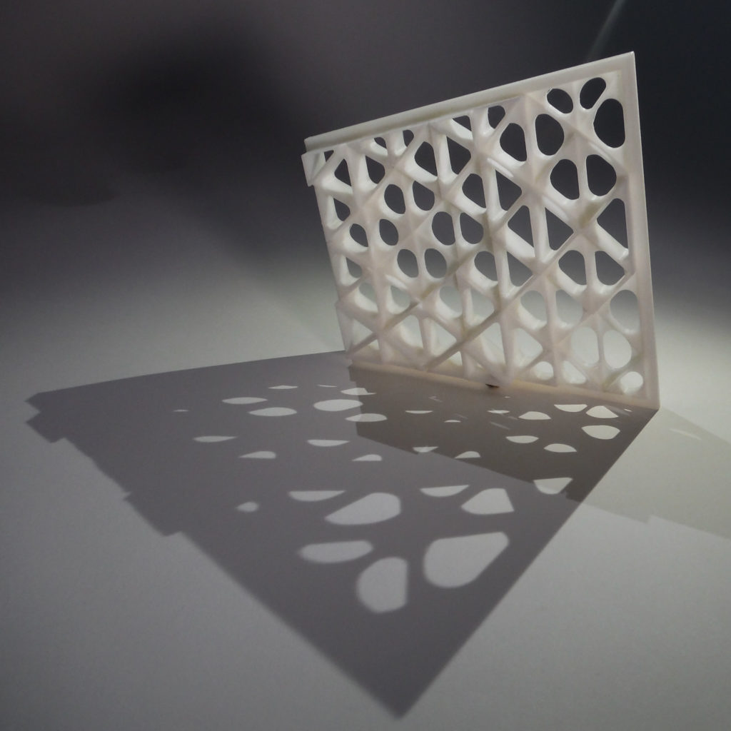
The goal of the exercise was to design a 1:1 Modul (155 x 165 mm)of a facade with a 3D printing technique.Therefore a total printing time of 8 hours was required.
Because of the size of the module and the limited time the design has to be developed in the way that it can be printed without additional support.
For final Modul the transparency as well as the perforation density for the facade shading had to be taken in consideration.

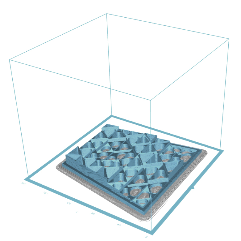
Estimated print time: 6h25m
Material usage: 40.41m(97g)
Printer: Zortrax M200 Plus
Material: Z-ABS 2
Nozzle diameter: 0.4 mm
Layer: 0.39 mm
Infill: 10%Raft Enabled: Yes
CNC Milling
17.10-21.10
Project Team Members:
- Jacob Lettl
- Paing Su Ko
- Somaih Medhat Bakr
Exploring the CNC Milling Outcome of 3D Scanned Models
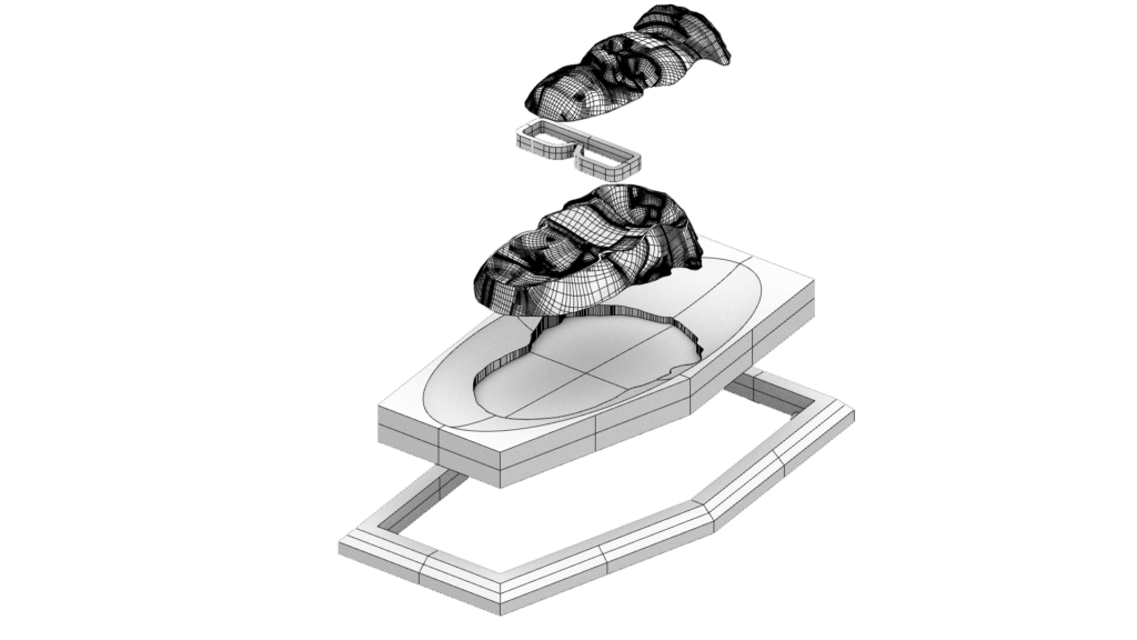
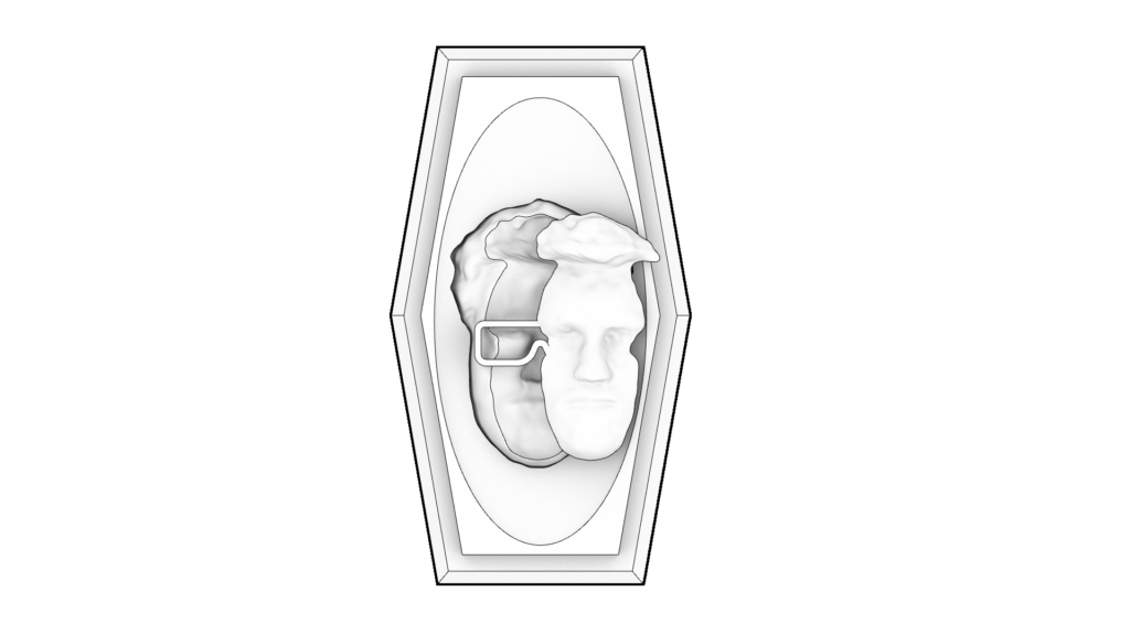
As shown in the animation above, we used a 3D scanning software to 3D scan one of the team member’s upper body and then upload that file to Rhino and convert the resulting meshes to subD and then into nurbs surfaces. We then modified to reach the desired end result.
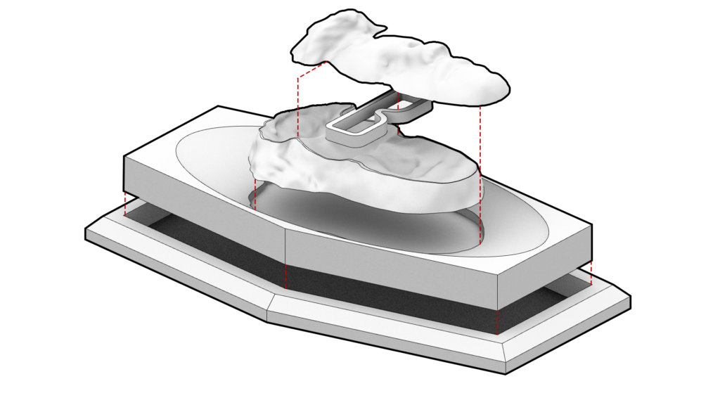
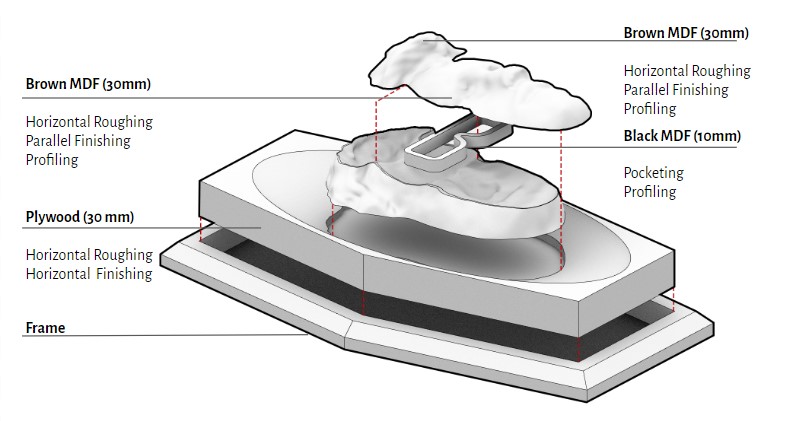
Axonometric Exploded diagram of the model
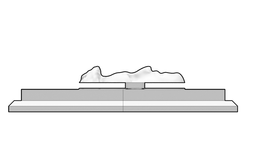
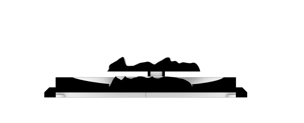
Longitudinal Section

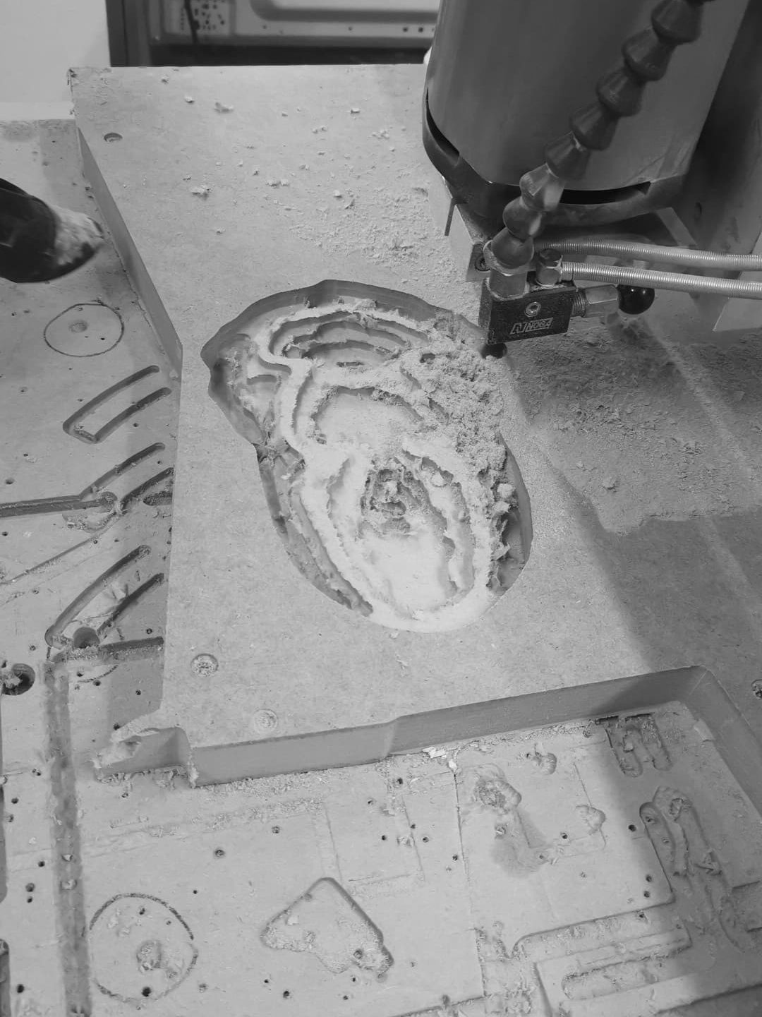
CNC Milling Process
Material: Plywood 30 mm, MDF 30mm MDF 10mm
Machine: Trex-S-1215 CNC Milling
Post Processor: CNC_STEP_BCNWorkpiece
Volume: Plywood Board: 380x180x30mm, Brown MDF Board: 225x155x30mm, Brown MDF Board: 225x120x30mm, Black MDF Board: 155x75x10mm
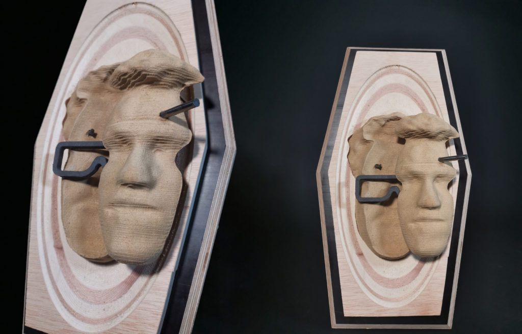
We decided to divide our model into 4 layers with suitable materials that would provide us with the desired textures, in order to explore how the CNC machine handles the different materials. We chose the plywood board to be the carved base beneath the face model, as we thought it would show different colours depending on the depth of the milling and on the grain direction of the board. As for the face, we thought the MDF would give us the smoothest and at the same time the firmest result. For the glasses we chose MDF as well, but we opted for the black colour to distinguish it from the brown MDF assigned for the face.
Operations Used
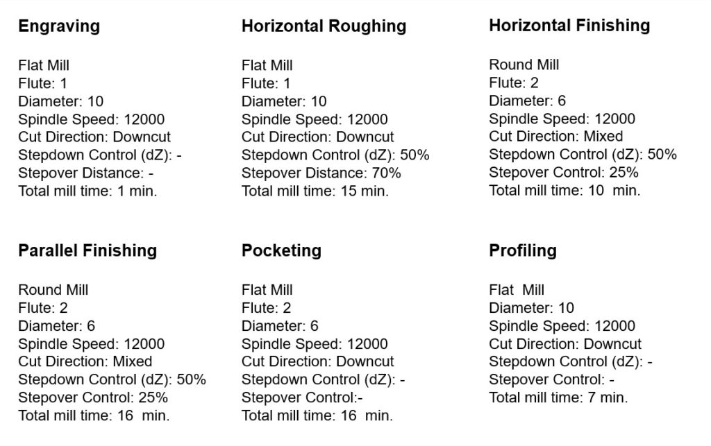
Before proceeding with our final CNC milling, we tried to implement the operations needed to achieve the desired face geometry on a foam sample to ensure that the operations would work fine and to experiment with the finishing operations.
We then went ahead and performed the operations on our previously selected materials.
We fixed all boards on the bed of the CNC machine using a drill driver to drill the screws into both the material and bed.
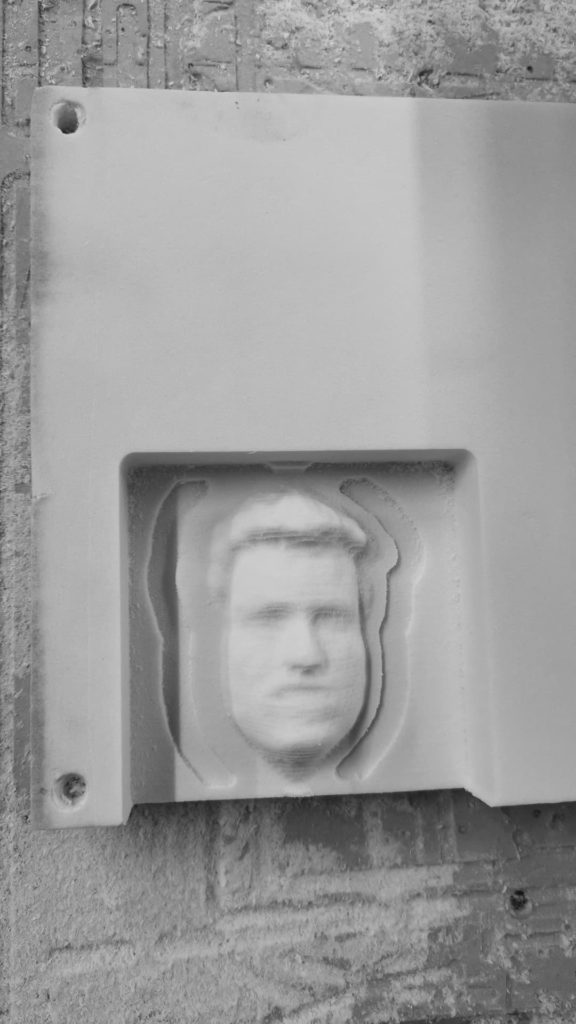
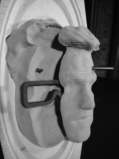
The resulting geometries especially the face layers needing sanding to smoothen the edges. The plywood board needed to be removed using a chisel after profiling, as a small thickness was not milled by the mill bit, then we used a belt sander to smoothen its edges.
We then assembled all the pieces in place, the lower face layer was fixed in its place carved within the plywood board and then the glasses and the upper face layer were glued into position.
“Integrating the inherent nature” is a project of IAAC, the Institute for Advanced Architecture of Catalonia, developed during the Master in Advanced Architecture (MAA01) 2020/21 by students: Paing Su Ko, Jacob Lettl, Somaih Medhat Bakr; faculty: Ricardo Mayor, Miguel Guerrero, Shyam Francesco Zonca; faculty assistant: Didac Torrent, Aslinur Taskin, Philipp Wienkämper.
