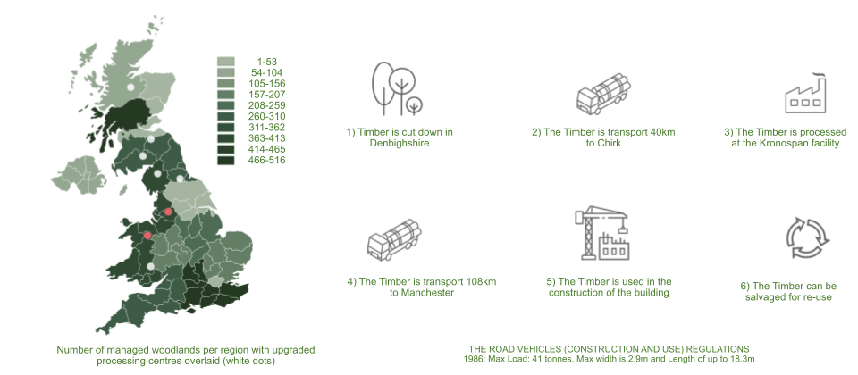
The aim of the project was to explore the timber grid-shell system. We have decided to look at this in the context of the U.K as the use of timber in construction has become contentious in recent years following the Grenfell tower catastrophe. However, if the UK is to reach its net zero goal, we see the wide scale adoption as an essential step as it offers the opportunity to reduce the net carbon footprint of the building by up to and over 100% through sequestration . Although currently a net importer, The government had made significant investments into timber processing setting up the foundations for a domestic timber production industry. The diagram shows how the project could act as a catalyst for the establishment of local supply chains and reduce carbon footprint.
We have chosen to look at the context of Manchester as it is a data rich environment. In recent years, Manchester has seen its skyline transformed with a boom in the number of high rise apartments being built (See Graph to the below). However, this development has often come at the price of neglecting the need for upgrades to basic infrastructure and amenities such as schools.

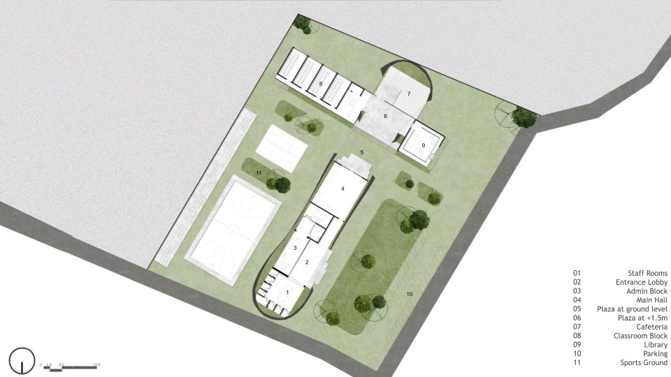
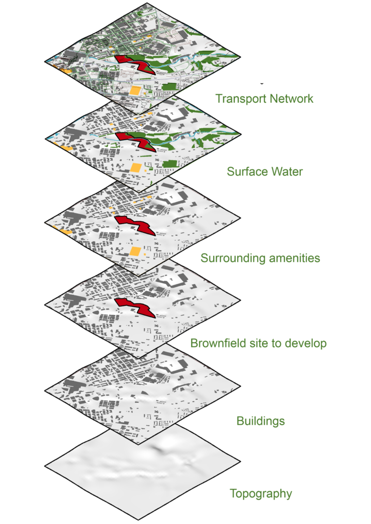
We analysed GIS data to help inform our site selection. A brownfield site was chosen, situated just outside the city centre and within walking distance of much of the recent development. We were able to extract a number of parameters which help to inform the positioning and layout of the building and program. These are shown below. The OSM and GIS data showed a distinct lack of amenities, which correlated with our research. This has helped us determine that our chosen typology. Our proposal will aim to develop a primary school to accommodate the rise in population.
From research, we found that Manchester has experienced around 10% population growth in the past 10 years mostly due to work related migration. We utilised the line method and population density provided by the census to calculate that there were approximately 9,6 thousand people within a 0.8km radius of our site. This was then combined with ONS + census data has shown that with the current school provision there would be a a surplus of 769 pupils in the area prompting the need for a new development.

The need for adaption led us to develop a schedule of accommodation tool in grasshopper using the department for educations BB103, which can accommodate desired pupil numbers and output the programmatic requirements
- Classrooms: Equation: C = P / (AreaPerPupilClassroom)
- Toilets: Equation: T = P * ToiletToPupilRatio
- Group Rooms: Equation: G = P / (AreaPerPupilGroupRoom)
- Store Rooms: Equation: S = P * AreaPerPupilStorage
- Hall: Equation: H = P / (AreaPerPupilHall)
- Kitchen: Equation: K = P / (AreaPerPupilKitchen)
- Studio: Equation: ST = P / (AreaPerPupilStudio)
- Office: Equation: O = StaffCount / (AreaPerStaffOffice)
- Staff Rooms: Equation: SR = StaffCount / (AreaPerStaffRoom)
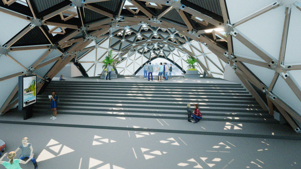
To gain a greater understanding of the grid shell system, we analysed the Forum by Wilkinson Eyre architects. The gridshell structure they developed features prefabricated glulam timbers and galvanized-steel nodes forming large triangular bays with an undulating dome. Standard timber sizes and custom-fabricated steel nodes enable the complex geometry. Construction involved a plywood skin, copper roof, and an intricate internal ceiling. Stiffening the structure was achieved using tubular steel edge supports. The design considered solar exposure, wind patterns, and precise modeling with Tekla and Autodesk software. The result delivers a modular system which deploys a mixture of panel types to respond to environmental and programmatic needs. From this analysis, we were able to gain an understanding that the nodes were the most expensive part of the structure, both in terms of cost and in terms of carbon.

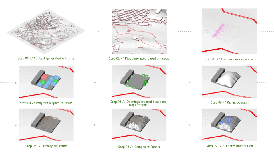
Our computational process then aimed to synthesize what we had learned into a design process. It unfolds as follows: initiating with context generation, followed by selecting a footprint within the plot boundary that meets area specifications. Calculations for building footprint values, considering entrance proximity, views, noise, and light, guide the selection. Program distribution follows these calculations, and openings are strategically placed based on functional requirements. Utilizing Kangaroo, the roof geometry is generated, succeeded by the creation of the structural system. Panels are then applied based on the face normals of the skin, and their placement is determined according to lighting requirements, creating a cohesive and systematic design process.
We were interested in looking at the distrtribution of the program on the site and its relationship to the context. Initially 3 approaches were tested as shown. the GIFs show how the program adapts to different site positions and conditions

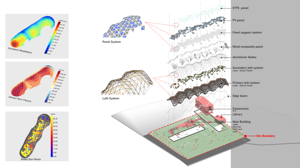
Our proposals developed the gridshell system within the computational model to account for structural members, nodes and panels types as shown. The model deploys a mixture of composite metal, photovoltaic (PV) and ETFE panels.

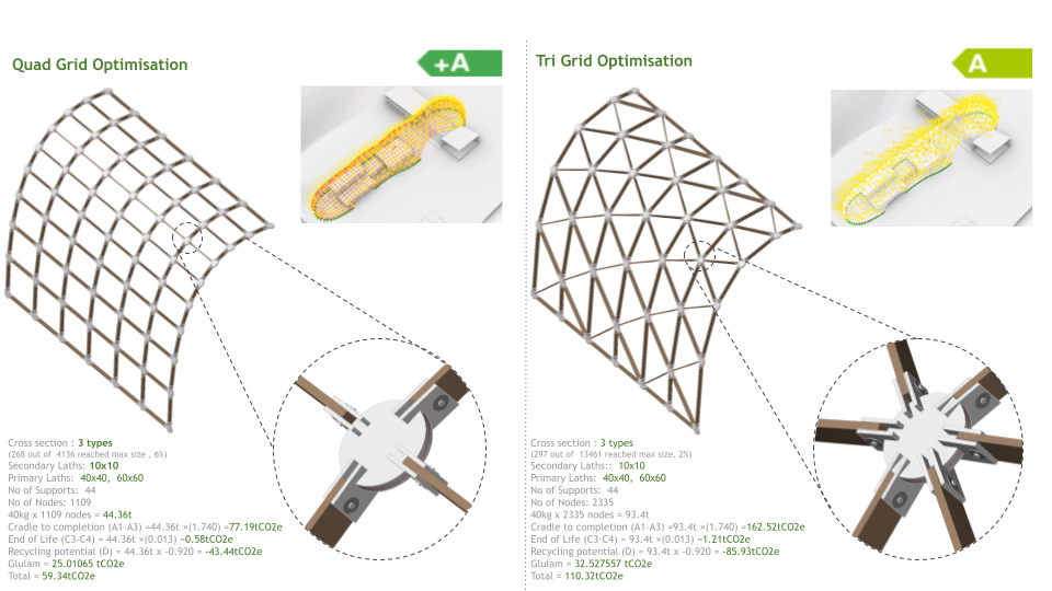
Through Karamba analysis and life cycle carbon testing, we were able to interrogate a number of different panel variations which were built into the model as options. As previously discussed, we found that the highest weighting factor in the carbon performance to be the number of nodes so a design looking to perform well in this area would try to minimize this. Further work on this project would look to optimize this, as well as the distribution of panels.
Environmental analysis was carried out to determine the location and distribution of both ETFE and PV panels.
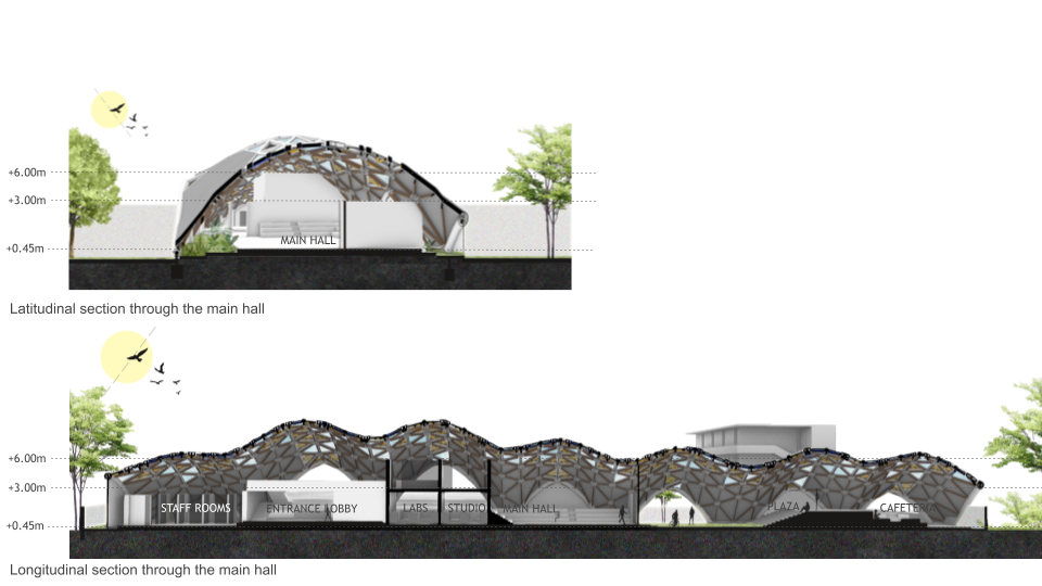
Architectural Drawings