Building Typology
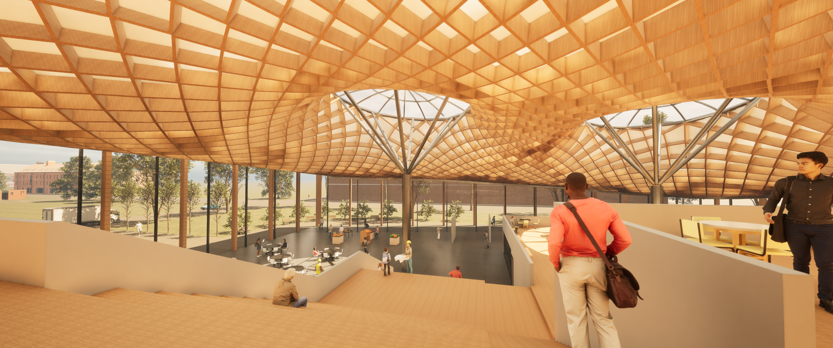
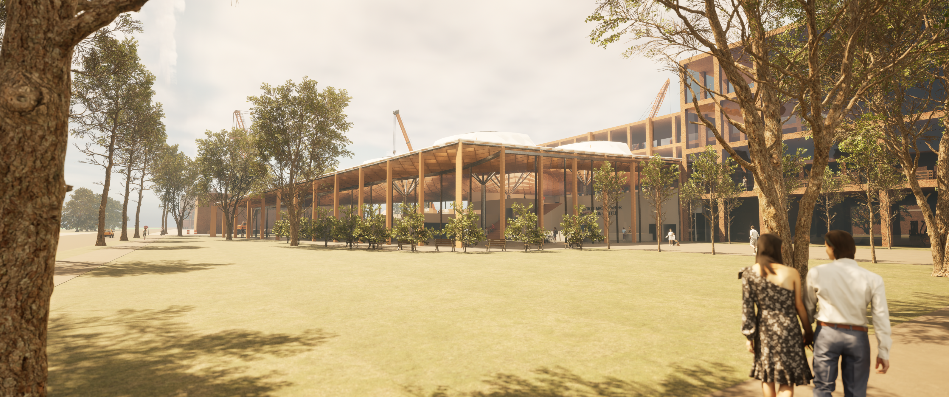
Our project focuses on exploring the opportunities and limitations when designing a timber gridshell system with a minimal surface roof structure. Minimal surfaces have a long history in mathematics and architecture, most notably Frei Otto and the infamous soap film experiments. Inspired by Otto’s Munich Olympic Stadium, we were interested to understand how we can use this logic to construct a gridshell system similar to the Savill Building Visitor Center, designed by Buro Happold.
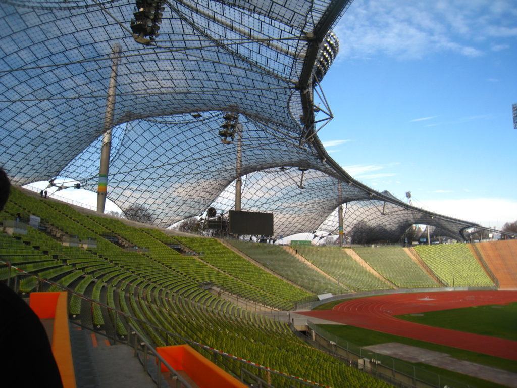
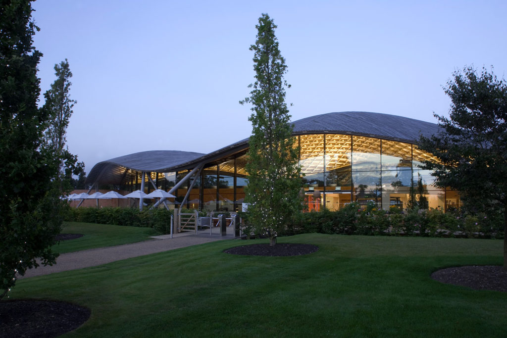
A minimal surface is a shape that locally minimizes its area. This often results in surface where the mean curvature is zero. The definition we utilized is that of a shape that, within a defined boundary, requires the least amount of material to enclose it. Does this offer us any structural benefit? How would designing a global architecture around this key point impact embodied carbon, environmental performance and aesthetics?
Site
Our project site is in Detroit, Michigan USA – one of the most well-known examples of urban decay in the world. In fact, in 2013, Detroit became the largest US municipality to file for bankruptcy. This happened for several reasons including the city’s close ties to the automotive industry’s success and failures; the bottom-line reason is that people began to leave the city, taking with them a reliable tax base.1 Most people working in the city commuted in; local communities were finding it difficult to economically contribute. Around the turn of the century, Detroit has seen a major resurgence in interest and building. Unfortunately, many of the efforts are currently focused on downtown.
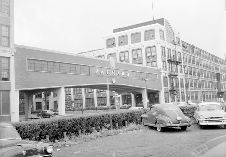
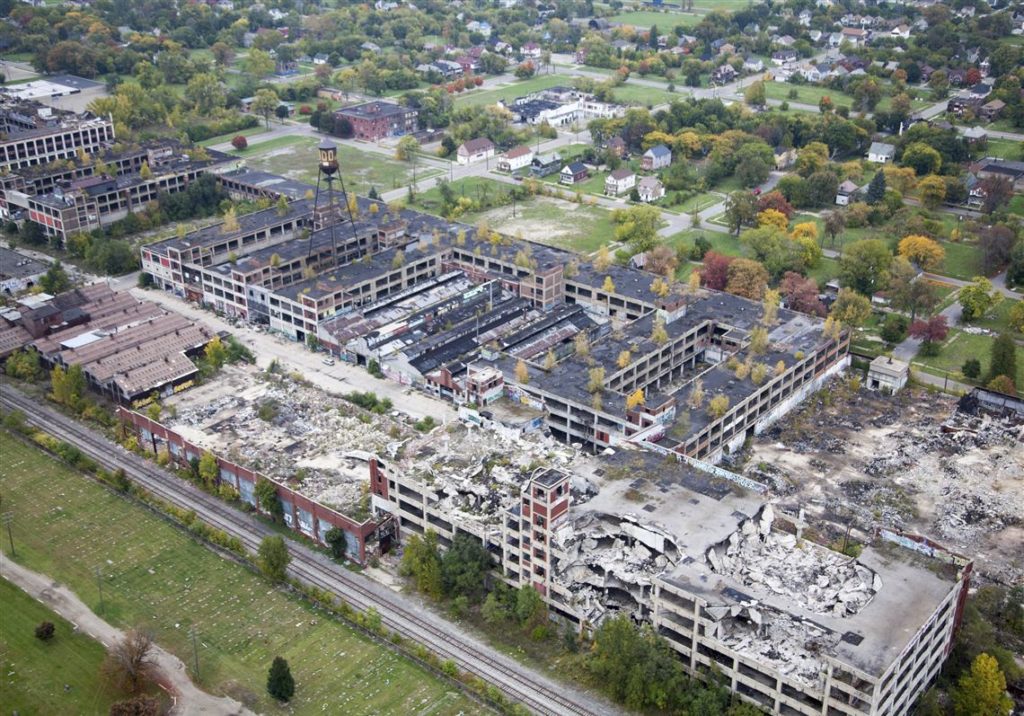
Packard Plant
In particular, our project will be an expansion of the now abandoned Packard Automotive Plant located in the Gratiot Town/Kettering neighborhood of east Detroit. Originally designed by Albert Kahn and opened in 1903, this 325,000m2 automobile manufacturing factory produced 1.6 million cars for the Packard Motor Company. The factory closed in 1958, was owned by other for a while but will eventually come to be seen as a symbol the Detroit’s difficult history.2
Proposed Program
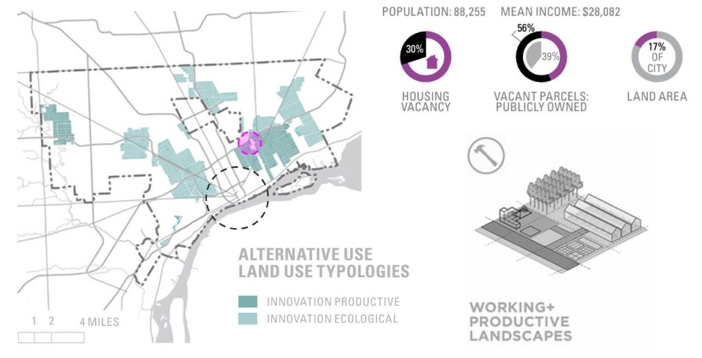
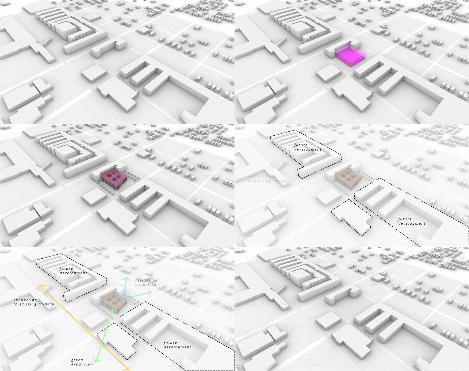
Given the site’s previous industrial use and very low vacancy, the Detroit Future City Strategic Framework3 designates this area as a “working and productive landscape”, one that would benefit the city greatly should we utilize productive landscapes as the basis for a sustainable city. Inspired by this vision, this space will serve as a mass timber production and education center, focused on ecological practices, sustainable innovation, local employment, and community building.
Our project will be an expansion to an existing portion of the Packard Plant. The existing building would be renovated to house mass timber production equipment while the renovation will offer public education and galleries, office and administrative rooms, a cafe, meeting and conference rooms, and community flexible gathering space.
Material Traceback
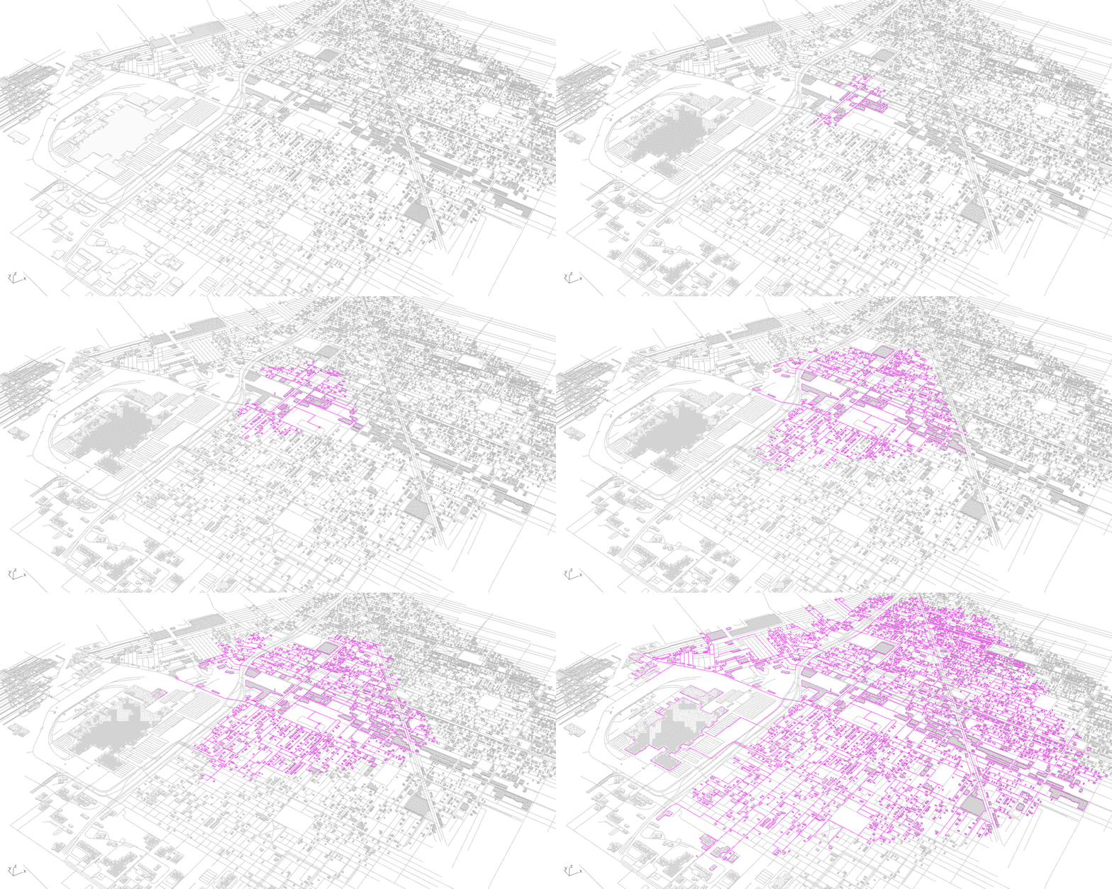
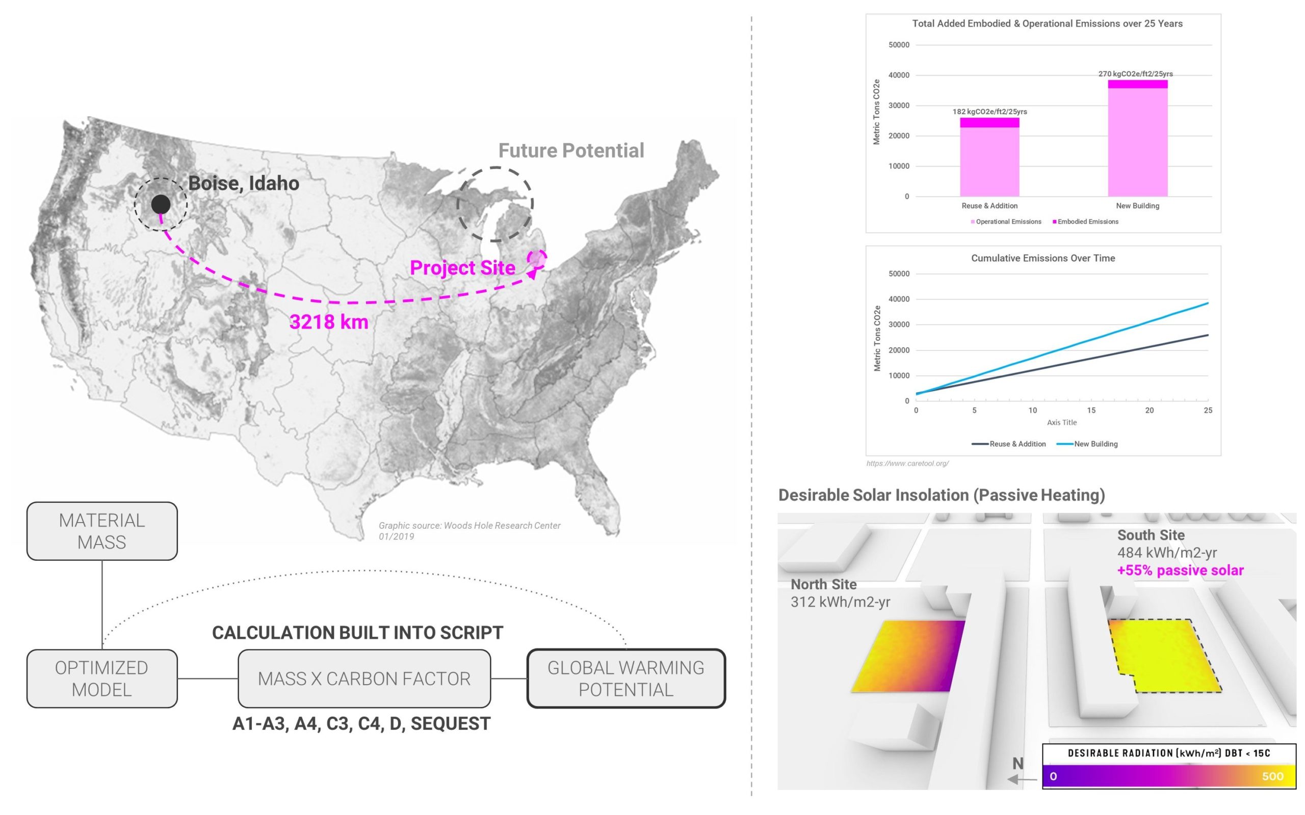
Given our Midwest location, the proposed project will have to source timber from elsewhere in the US. Once constructed, the goal would be for this facility to support and encourage more mass timber construction in the Midwest. The distance traveled is considered and incorporated in our design optimization (described later). Importantly, we calculated the total Global Warming Potential (kgCO2e) per m2 for the global architecture, including floor slabs, columns, and minimal surface roof. Our script included embodied carbon from sectors A1-A3, A4, C3, C4, and D in the Life Cycle Analysis of carbon.
We found an additional benefit in repurposing an existing building instead of additional building demolition. Over 25 years, it was estimated that we would expend less carbon (embodied and operational) keeping all else the same including square meters program requirements. Finally, we selected the southern site close to the main road, Grand Blvd, as it allowed for minimal demolition work as more passive solar heating potential compared to a northern site.
System Parameterization
We developed a highly flexible Grasshopper script within Rhino3D that allows a designer to simply draw a boundary and define major architectural inputs in order to generate a working structural architecture. In our workflow, we explored environmental impacts (daylighting, harmful solar radiation, beneficial solar radiation) throughout the design process. Structural and geometric optimization is embedded within the script to inform our final architectural decisions.
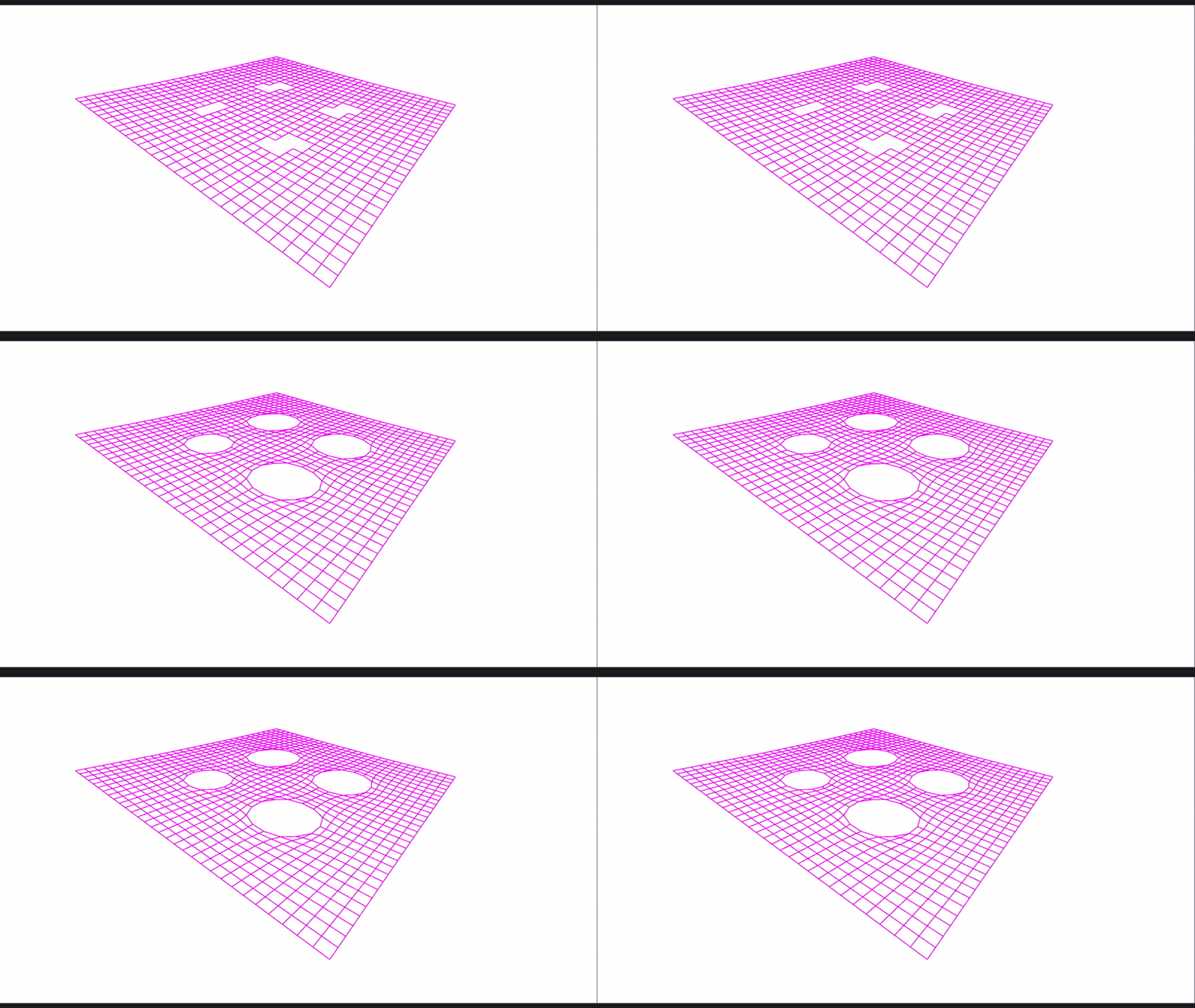
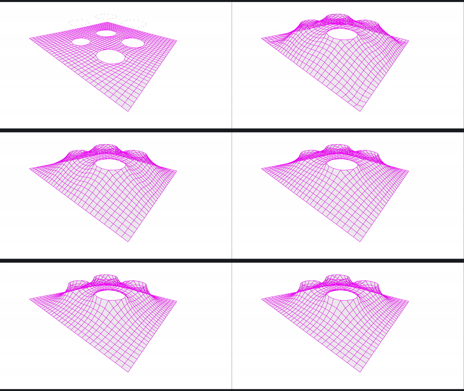
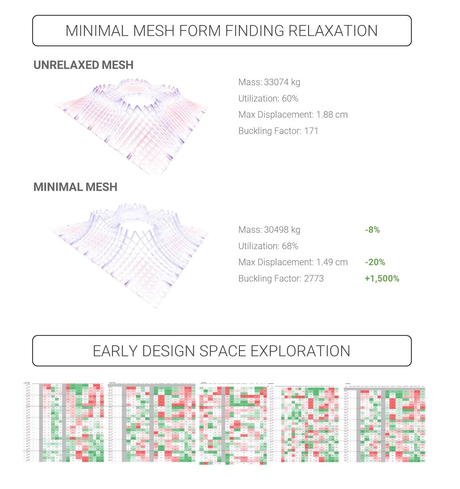
For form finding, it is critical for future analysis to maintain a clean base mesh typology and avoid creating mesh singularities. Using Kangaroo, we developed a method to find a minimal surface while maintaining a clean and organized grid so that Karamba3D would perform calculations on a simple and intuitive FE model. We have two relaxation stages. The first stage creates circular skylight openings in the roof. The second relaxation stage gives the roof its minimal curvature. Critically, when compared to an idea roof structure and planar roof beams, the curved minimal surface mesh performed better structurally. The curvature in the roof members allowed the system to reduce overall mass, maintain a 70% utilization, and significantly increase the buckling factor. This is important as buckling is often the way most gridshells will structurally fail. With this understanding and proof of our minima surface form finding technique, we moved on developing a multi-objective optimization engine.


Design Exploration and Optimization
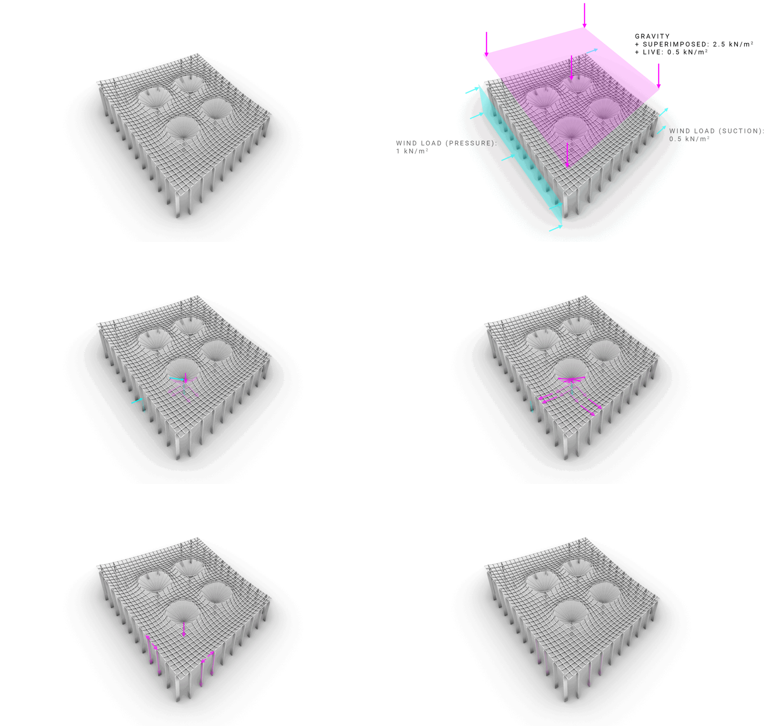
Almost every parameter within our system is adjustable. For this reason, we employed Wallacei X, an evolutionary solver, to iterate through thousands of possible combinations and provide us with viable “ideal” solutions. Our goals were to minimize maximum displacement, minimize maximum utilization, minimize kgCO2e/m2, minimize mean curvature, and maximize the buckling factor. Importantly, Karamba3D is performing a cross-section optimization on all possible configurations, utilizing the load combinations below with a maximum utilization goal of 70%.
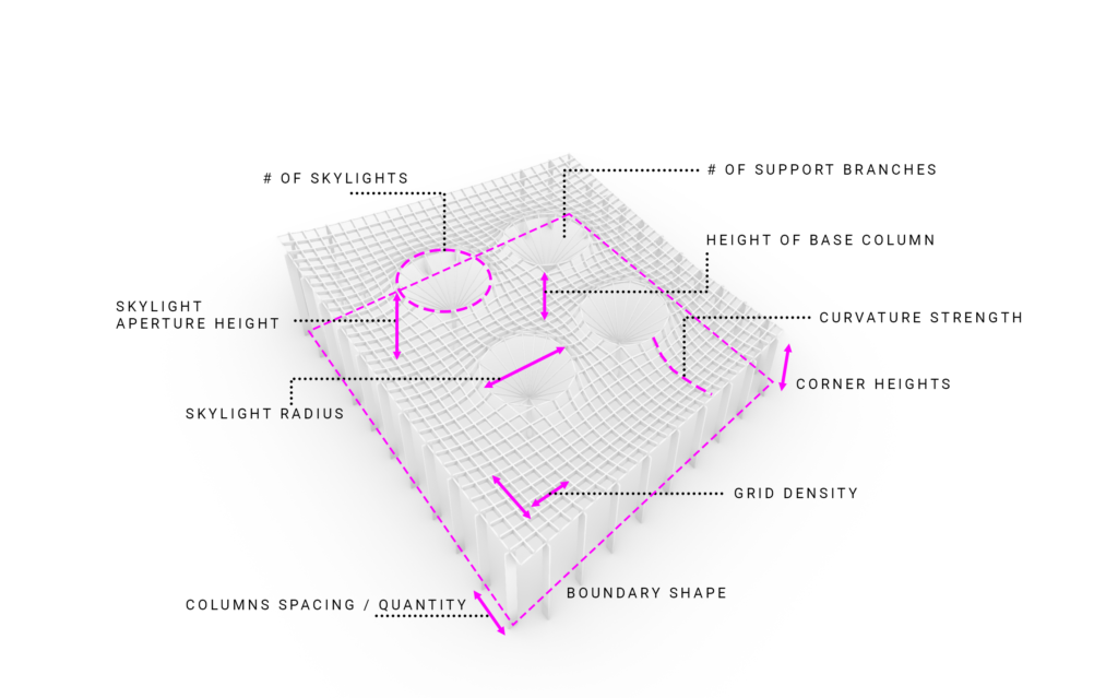
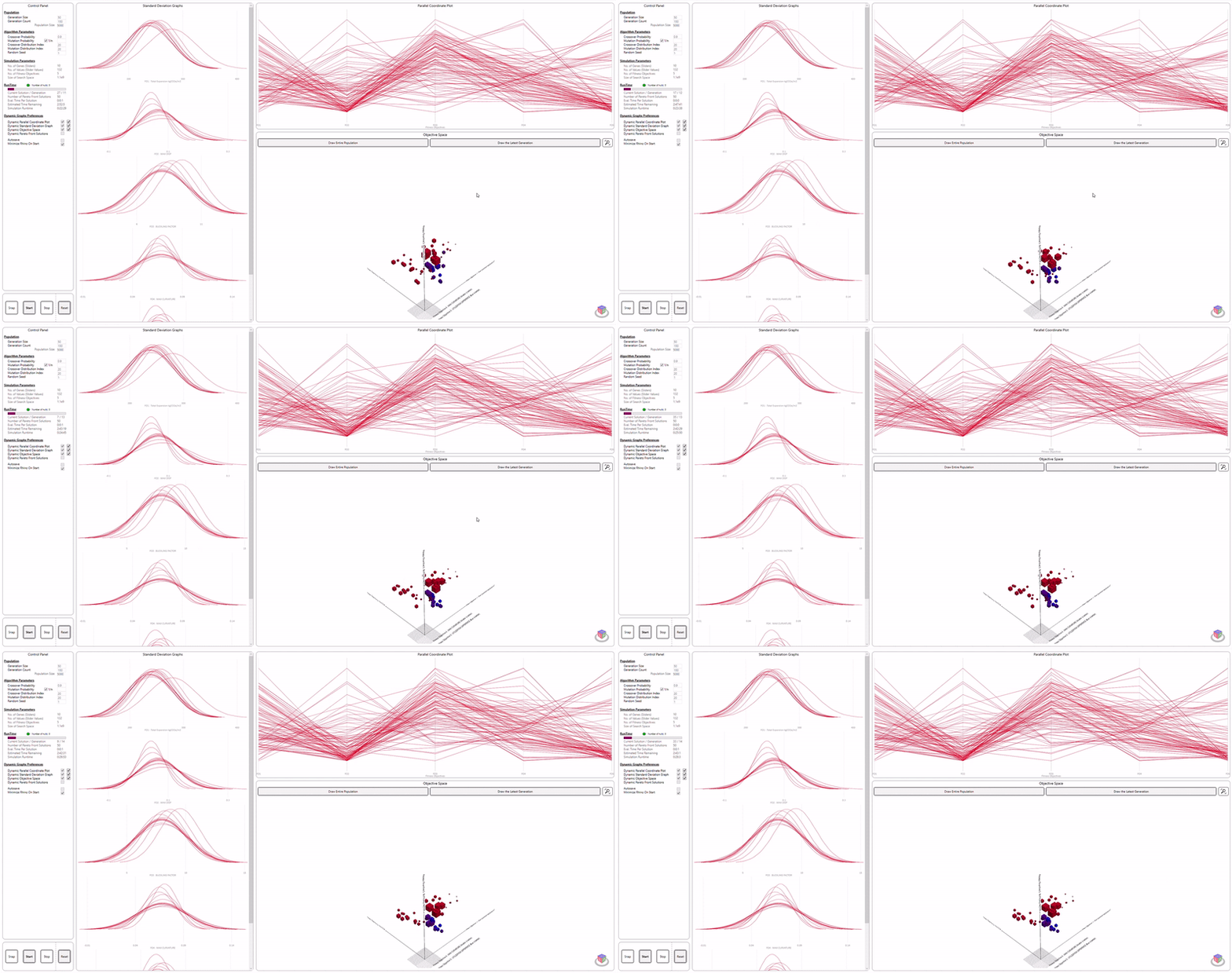
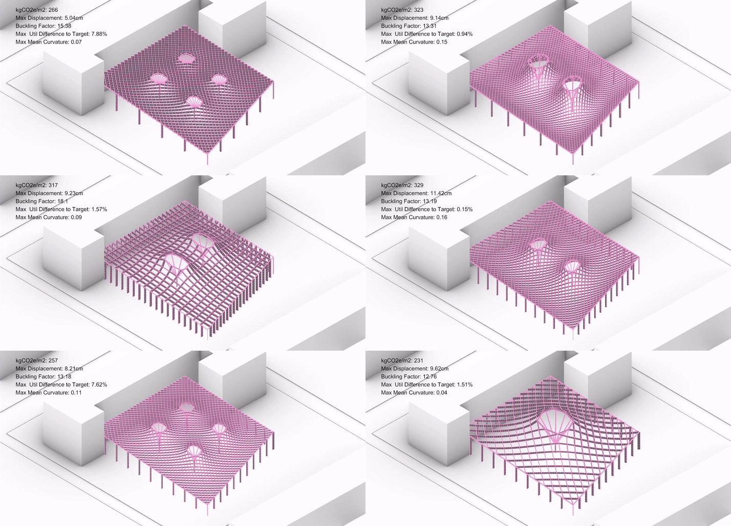
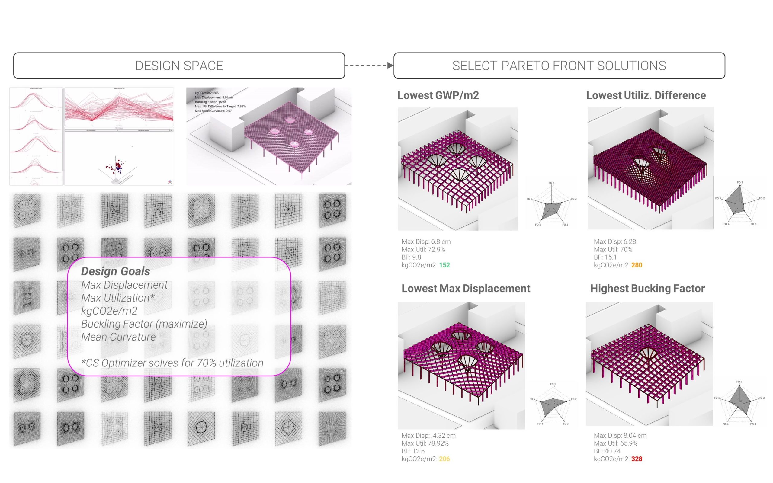
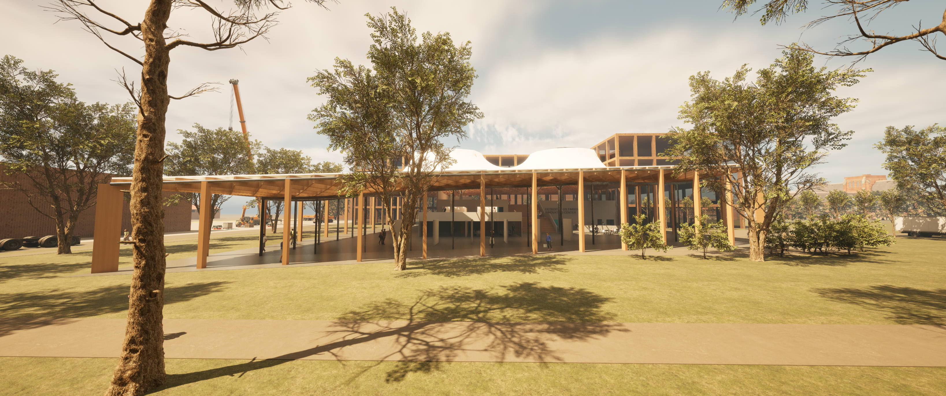
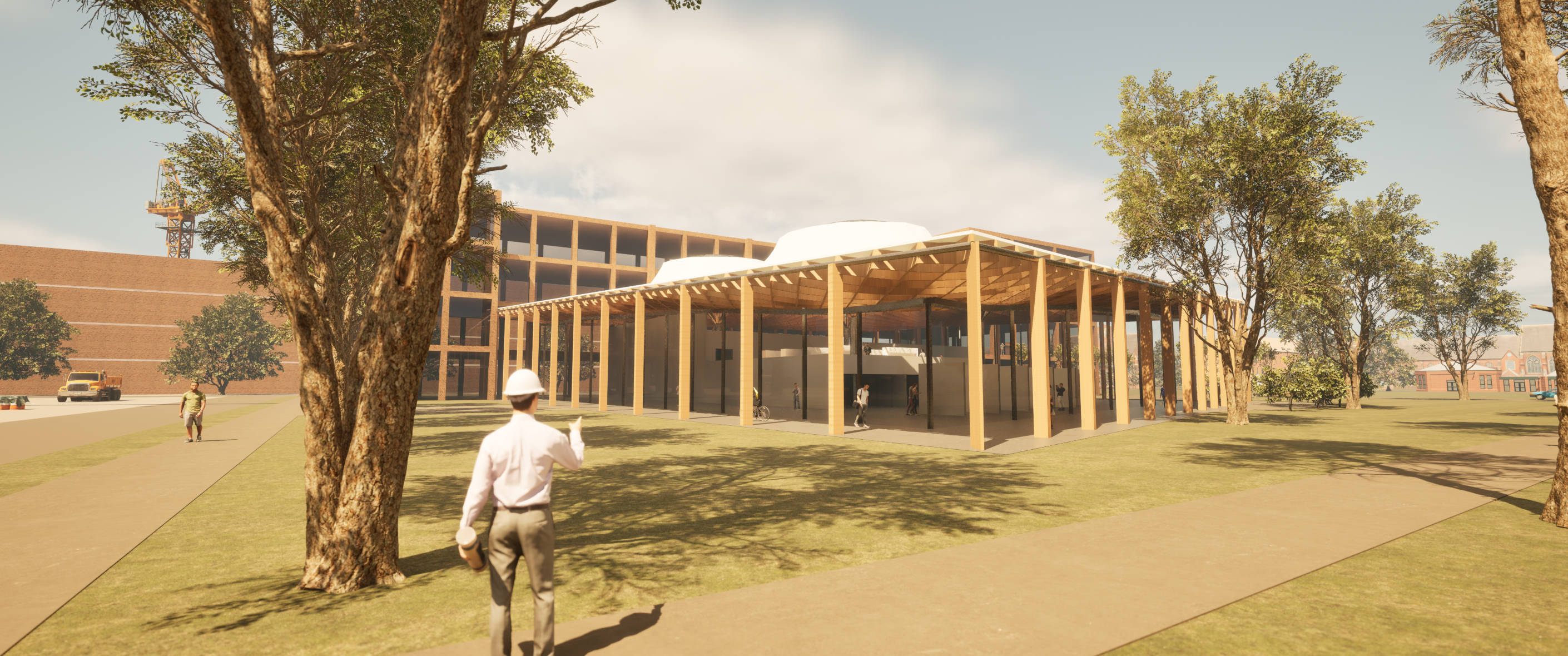
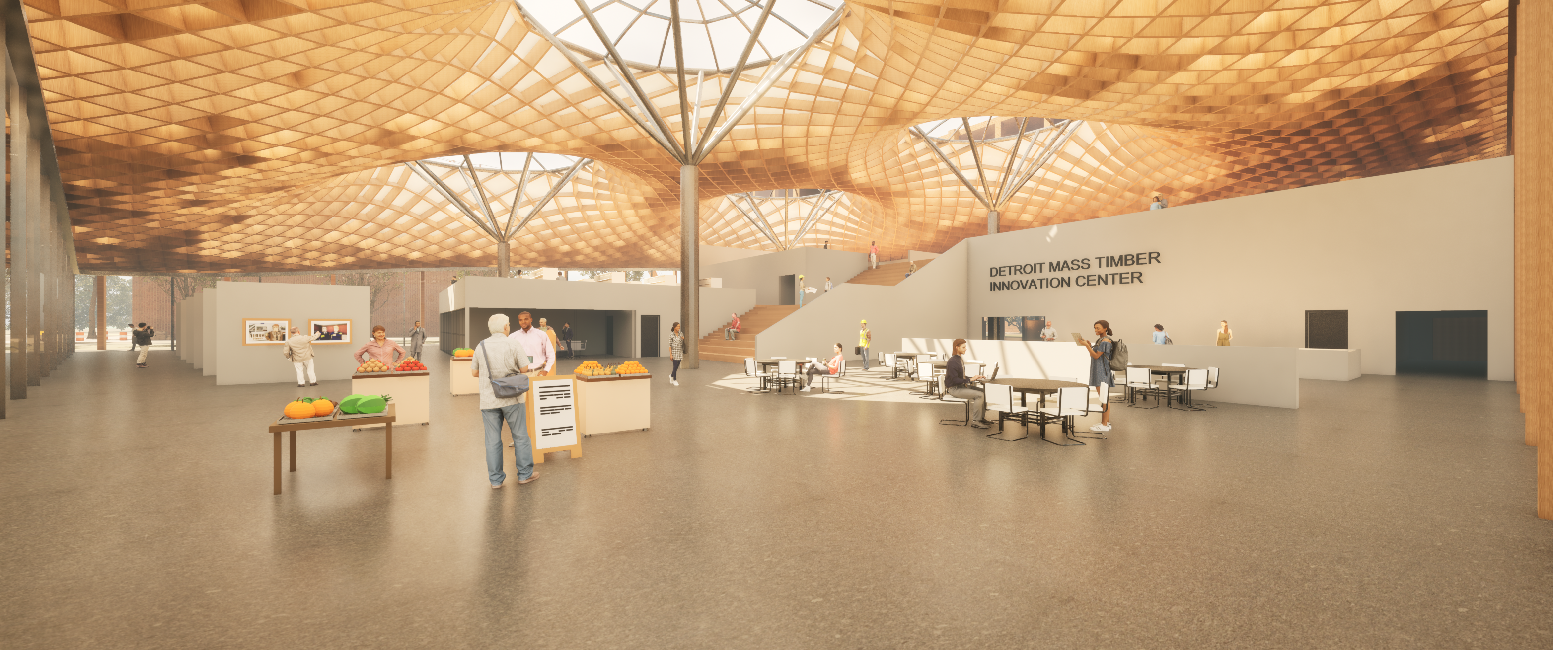
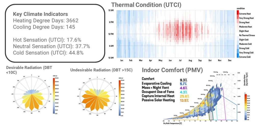
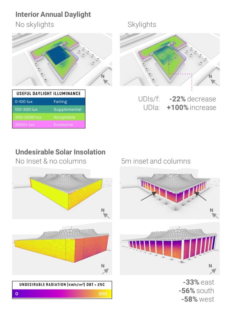
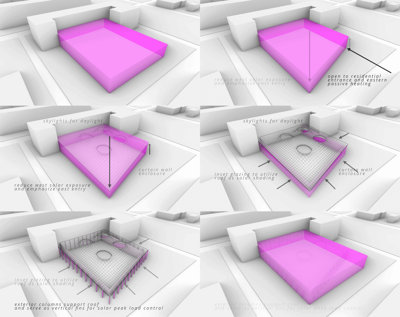
While exploring the various pareto front solutions, we also considered environmental performance. Our final architectural direction is based on the MOO solutions and daylighting and solar load performance (maximize interior daylight while minimizing glare, maximize beneficial passive solar radiation for energy and indoor comfort, and minimize western peak solar load). Seen below, we illustrate how the facade enclosure, structural and environmental performance, aesthetics, and context relations are all considered in the final design.
Final Design
Structural
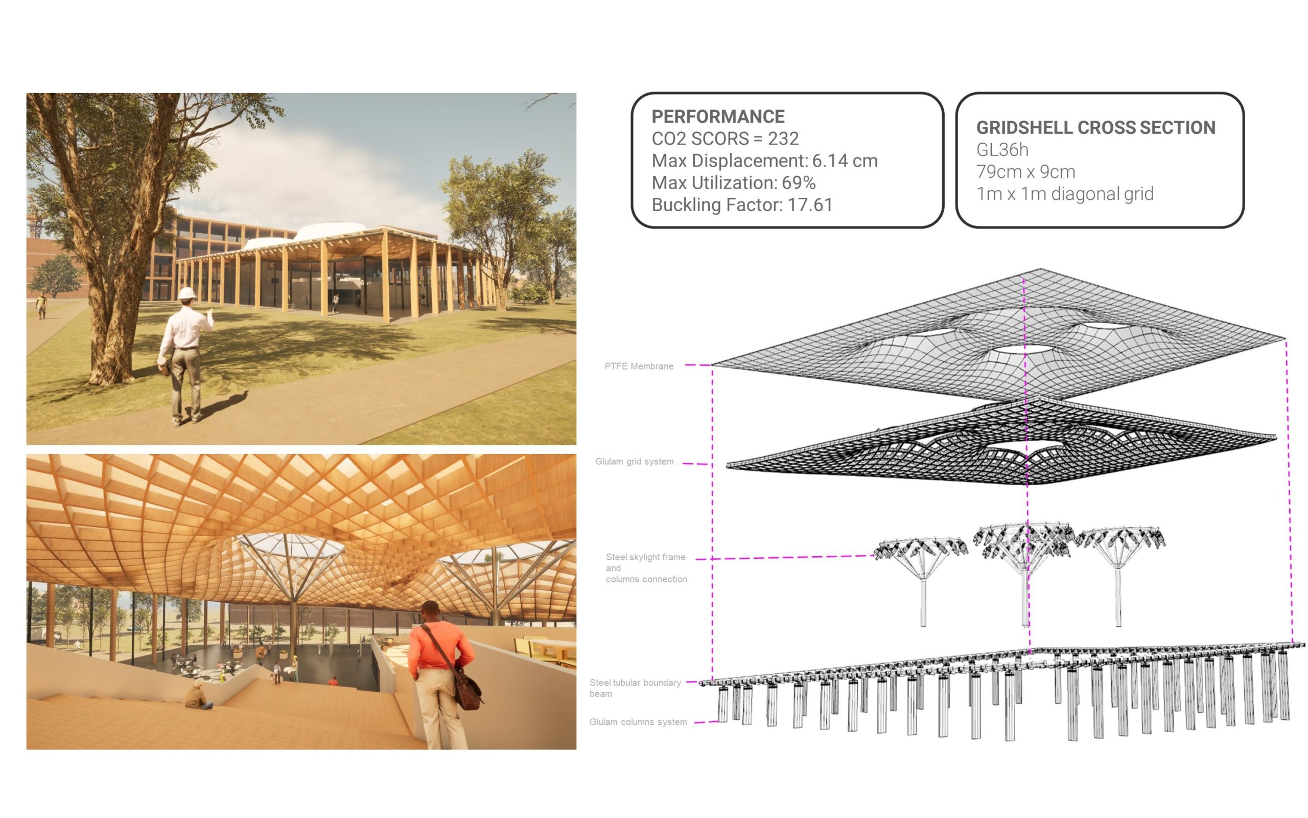
Our final design performed relatively well structurally while also minimizing embodied carbon. The final roof design utilizes 79cm x 9cm GL36h curved glulam beams spaced in a 1m x 1m diagonal grid. The roof membrane is a white PTFE material to allow for diffuse daylighting and striking nighttime glowing appearance.
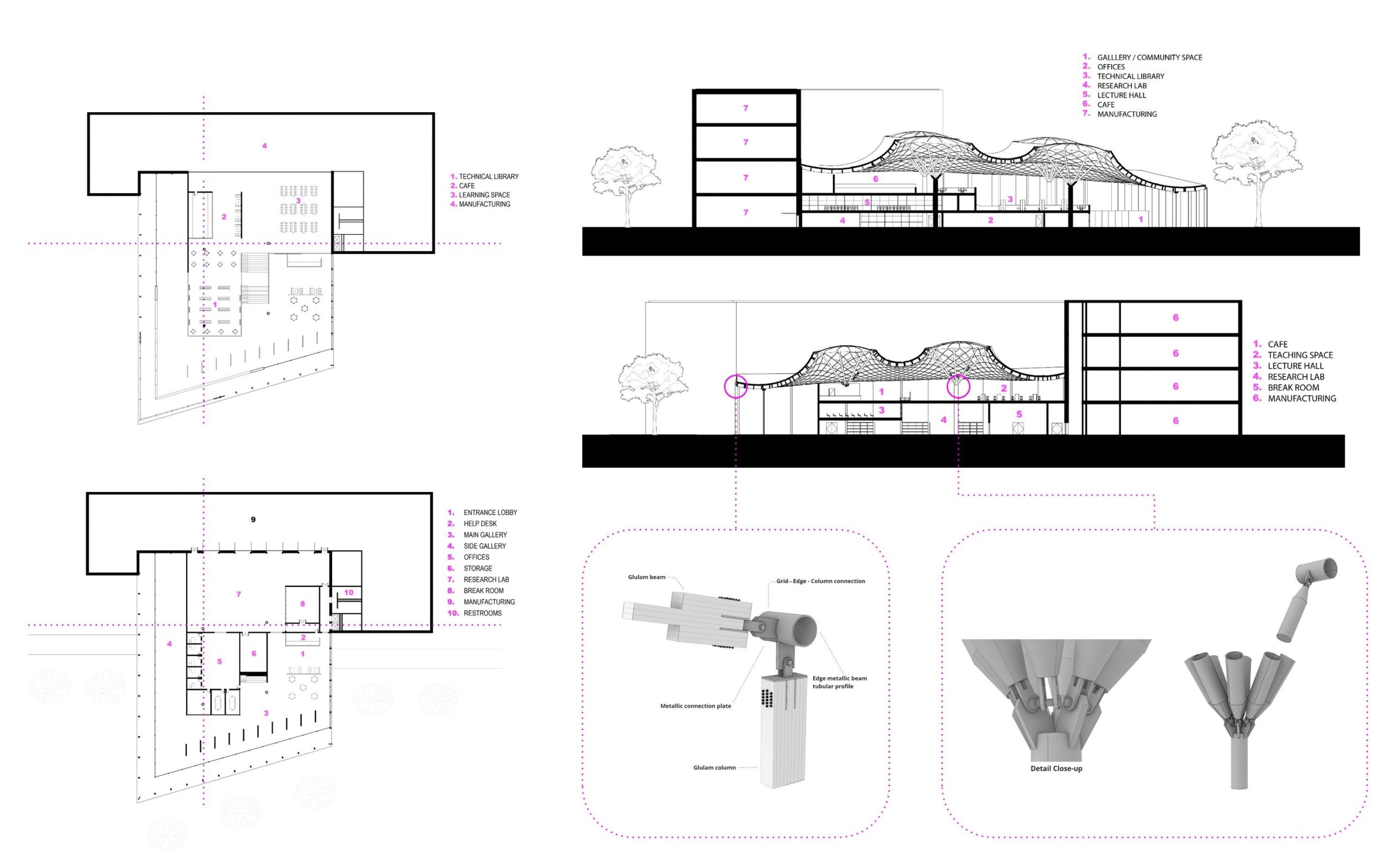
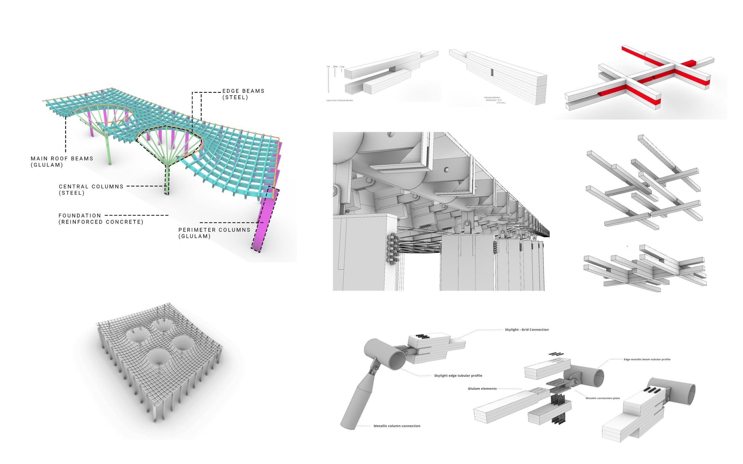
The system is detailed below. Importantly, the glulam members are design so that the middle portions of the timber stack are offset. The overlapping members are each joint is provides rigidity to the system, much a like a brick wall. Steel central columns and edges interface with the glulam roof and perimeter columns to effectively distribute load and meet utilization requirements.
Technical Drawings
In section, the expansion space connects and aligns with the existing building’s first and second floors. This offers an open transition and across spaces and encourages the public to witness and understand mass timber production process. The asymmetric boundary gives the roof an iconic look while creating a large and open public space.
